For feedback, use the following:
ipd_online_feedback@alcatel-lucent.com
Table of Contents Previous Next Index PDF


System Management
In This Chapter
This chapter provides information about configuring basic system management parameters.
Topics in this chapter include:
System Management Parameters
System management commands allow you to configure basic system management functions such as the system name, the router’s location and coordinates, and CLLI code as well as time zones, Network Time Protocol (NTP), Simple Network Time Protocol (SNTP) properties, CRON and synchronization properties.
It is possible to query the DNS server for IPv6 addresses. By default the DNS names are queried for A-records only (address-preference is IPv4-only). If the address-preference is set to IPv6 first, the DNS server will be queried for AAAA-records first, and if there is no successful reply, then A-records.
 
System Information
System information components include:
 
System Name
The system name is the MIB II (RFC 1907, Management Information Base for Version 2 of the Simple Network Management Protocol (SNMPv2)) sysName object. By convention, this text string is the node’s fully-qualified domain name. The system name can be any ASCII printable text string of up to 32 characters.
 
System Contact
The system contact is the MIB II sysContact object. By convention, this text string is a textual identification of the contact person for this managed node, together with information on how to contact this person.The system contact can be any ASCII printable text string of up to 80 characters.
 
 
System Location
The system location is the MIB II sysLocation object which is a text string conventionally used to describe the node’s physical location, for example, “Bldg MV-11, 1st Floor, Room 101”. The system location can be any ASCII printable text string of up to 80 characters.
 
System Coordinates
The system coordinates is the ­Alcatel-Lucent Chassis MIB tmnxChassisCoordinates object. This text string indicates the Global Positioning System (GPS) coordinates of the location of the chassis.
Two-dimensional GPS positioning offers latitude and longitude information as a four dimensional vector:
where direction is one of the four basic values: N, S, W, E, hours ranges from 0 to 180 (for latitude) and 0 to 90 for longitude, and minutes and seconds range from 0 to 60.
<W, 122, 56, 89> is an example of longitude and <N, 85, 66, 43> is an example of latitude.
System coordinates can be expressed in different notations, examples include:
The system coordinates can be any ASCII printable text string up to 80 characters.
 
Naming Objects
It is discouraged to configure named objects with a name that starts with “_tmnx_” and with “_” in general.
 
Common Language Location Identifier
A Common Language Location Identifier (CLLI) code string for the device is an 11-character standardized geographic identifier that uniquely identifies the geographic location of places and certain functional categories of equipment unique to the telecommunications industry. The CLLI code is stored in the ­Alcatel-Lucent Chassis MIB tmnxChassisCLLICode object.
The CLLI code can be any ASCII printable text string of up to 11 characters.
 
System Time
7750 SR-Series routers are equipped with a real-time system clock for time keeping purposes. When set, the system clock always operates on Coordinated Universal Time (UTC), but the 7750 SR OS software has options for local time translation as well as system clock synchronization.
System time parameters include:
 
Time Zones
Setting a time zone in SR OS allows for times to be displayed in the local time rather than in UTC. The SR OS has both user-defined and system defined time zones.
A user-defined time zone has a user assigned name of up to four printable ASCII characters in length and unique from the system-defined time zones. For user-defined time zones, the offset from UTC is configured as well as any summer time adjustment for the time zone.
The SR OS system-defined time zones are listed in Table 21 which includes both time zones with and without summer time correction.
 
 
Network Time Protocol (NTP)
NTP is the Network Time Protocol defined in RFC 1305, Network Time Protocol (Version 3) Specification, Implementation and Analysis and RFC 5905, Network Time Protocol Version 4: Protocol and Algorithms Specification. It allows for the participating network nodes to keep time more accurately and more importantly they can maintain time in a more synchronized fashion between all participating network nodes.
NTP uses stratum levels to define the number of hops from a reference clock. The reference clock is considered to be a stratum-0 device that is assumed to be accurate with little or no delay. Stratum-0 servers cannot be used in a network. However, they can be directly connected to devices that operate as stratum-1 servers. A stratum-1 server is an NTP server with a directly-connected device that provides Coordinated Universal Time (UTC), such as a GPS or atomic clock. The 7750 SR-7 and 7750 SR-12 devices cannot act as stratum-1 servers but can act as stratum-2 devices as a network connection to an NTP server is required.
The higher stratum levels are separated from the stratum-1 server over a network path, thus, a stratum-2 server receives its time over a network link from a stratum-1 server. A stratum-3 server receives its time over a network link from a stratum-2 server.
The following NTP elements are supported:
Broadcast or multicast modes — When operating in these modes, the node will receive or send using either a multicast (default 224.0.1.1) or a broadcast address. Multicast is supported on the MGMT port.
In order to facilitate proper operation once the standby CPM takes over from the active CPM it is required that the time on the secondary CPM is synchronized with the clock of the active CPM.
 
SNTP Time Synchronization
For synchronizing the system clock with outside time sources, the SR OS includes a Simple Network Time Protocol (SNTP) client. As defined in RFC 2030, SNTP Version 4 is an adaptation of the Network Time Protocol (NTP). SNTP typically provides time accuracy within 100 milliseconds of the time source. SNTP can only receive the time from NTP servers; it cannot be used to provide time services to other systems. SNTP is a compact, client-only version of NTP. SNTP does not authenticate traffic.
SNTP can be configured in both unicast client modes (point-to-point) and broadcast client modes (point-to-multipoint). SNTP should be used only at the extremities of the synchronization subnet. SNTP clients should operate only at the highest stratum (leaves) of the subnet and in configurations where no NTP or SNTP client is dependent on another SNTP client for synchronization. SNTP time servers should operate only at the root (stratum 1) of the subnet and then only in configurations where no other source of synchronization other than a reliable radio clock is available. External servers may only be specified using IPv4 addresses.
In the SR OS, the SNTP client can be configured for either broadcast or unicast client mode.
 
CRON
The CRON feature supports the Service Assurance Agent (SAA) functions as well as the ability to schedule turning on and off policies to meet “Time of Day” requirements. CRON functionality includes the ability to specify the commands that need to be run, when they will be scheduled, including one-time only functionality (one-shot), interval and calendar functions, as well as where to store the output of the results. In addition, CRON can specify the relationship between input, output and schedule. Scheduled reboots, peer turn ups, service assurance agent tests and more can all be scheduled with Cron, as well as OAM events, such as connectivity checks, or troubleshooting runs.
CRON features are saved to the configuration file on both primary and backup control modules. If a control module switchover occurs, CRON events are restored when the new configuration is loaded. If a control module switchover occurs during the execution of a cron script, the failover behavior will be determined by the contents of the script.
CRON features run serially with at least 255 separate schedules and scripts. Each instance can support a schedule where the event is executed any number of times.
The following CRON elements are supported:
Time of Day — Time of Day (TOD) suites are useful when configuring many types of time-based policies or when a large number of subscribers or SAPs require the same type of TOD changes. The TOD suite may be configured while using specific ingress or egress ACLs or QoS policies, and is an enhancement of the ingress and egress CLI trees.
High Availability
This section discusses the high availability (HA) routing options and features available to service providers that help diminish vulnerability at the network or service provider edge and alleviate the effect of a lengthy outage on IP networks.
High availability is an important feature in service provider routing systems. High availability is gaining momentum due to the unprecedented growth of IP services and applications in service provider networks driven by the demand from the enterprise and residential communities. Downtime can be very costly, and, in addition to lost revenue, customer information and business-critical communications can be lost. High availability is the combination of continuous uptime over long periods (Mean Time Between Failures (MTBF)) and the speed at which failover or recovery occurs (Mean Time To Repair (MTTR).
The popularity of high availability routing is evident at the network or service provider edge where thousands of connections are hosted and rerouting options around a failed piece of equipment can often be limiting. Or, a single access link exists to a customer because of additional costs for redundant links. As service providers converge business-critical services such as real-time voice (VoIP), video, and VPN applications over their IP networks, high availability becomes much more stringent compared to the requirements for best-effort data. Network and service availability become critical aspects when offering advanced IP services which dictates that IP routers that are used to construct the foundations of these networks be resilient to component and software outages.
For high availability configuration information, refer to Synchronization and Redundancy.
 
 
HA Features
As more and more critical commercial applications move onto the IP/MPLS networks, providing high availability services becomes increasingly important. This section describes high availability features for routers. Most of these features only apply to routers with two Control Processor Modules (CPM), currently the 7750 SR-7, SR-12, and SR-c12 s.
 
Redundancy
The redundancy features enable the duplication of data elements and software functionality to maintain service continuation in case of outages or component failure.
Refer to the 7750 SR-Series OS Integrated Services Adapter Guide for information about redundancy for the Integrated Service Adapter (ISA).
 
Software Redundancy
Software outages are challenging even when baseline hardware redundancy is in place. There should be a balance to provide high availability routing otherwise router problems typically propagate not only throughout the service provider network, but also externally to other connected networks possibly belonging to other service providers. This could affect customers on a broad scale. Presently, there are several software availability features that contribute to the percentage of time that a router is available to process and forward traffic.
To fully appreciate high availability you should realize that all routing protocols specify minimum time intervals in which the peer device must receive an acknowledgement before it disconnects the session.
Therefore, router software has to recover faster than the specified time interval to maintain up time.
 
Configuration Redundancy
Features configured on the active device CPM are saved on the standby CPM as well. When the active device CPM fails, these features are brought up on the standby device CPM that takes over the mastership.
Even with modern modular and stable software, the failure of route processor hardware or software can cause the router to reboot or cause other service impacting events. In the best circumstances, failure leads to the initialization of a redundant route processor, which hosts the standby software configuration, to become the active processor. The following options are available.
 
Component Redundancy
7750 SR-Series component redundancy is critical to reduce MTTR for the system and primarily consists of the following router features:
Dual route processor modules — For a highly available architecture, redundant route processors (RPs) or Control Processor Modules(CPM) are essential. The route processor calculates the most efficient route to an Internet destination and communicates the best path information to peer routers. Rapid information synchronization between the primary and secondary route processor is crucial to minimize recovery time.
Dual switch fabric — Failover to the backup switch fabric within a minimum time interval, preferably with no loss of traffic.
Router hardware architecture plays a key role in the availability of the system. The principle router architecture styles are centralized and distributed. In these architectures, both active and standby route processors, I/O modules (IOMs) (also called line cards), fans, and power supplies maintain a low MTTR for the routing system.
However, in a centralized architecture, packet processing and forwarding is performed in a central shared route processor and the individual line cards are relatively simple. The cards rely solely on the route processor for routing and forwarding intelligence and, should the centralized route processor fail, there is greater impact to the system overall, as all routing and packet forwarding will stop.
In a distributed system, the packet forwarding functionality is situated on each line card. Distributing the forwarding engines off the central route processor and positioning one on each line card lowers the impact of route processor failure as the line cards can continue to forward traffic during an outage.
The distributed system is better suited to enable the convergence of business critical services such as real-time voice (VoIP), Video, and VPN applications over IP networks with superior performance and scalability. The centralized architecture can be prone to performance bottleneck issues and limits service offerings through poor scalability which may lead to customer and service SLA violations.
 
Service Redundancy
All service-related statistics are kept during a switchover. Services, SDPs, and SAPs will remain up with a minimum loss of forwarded traffic during a CPM switchover.
 
Accounting Configuration Redundancy
When there is a switchover and the standby CPM becomes active, the accounting servers will be checked and if they are administratively up and capable of coming online (media present, etc.), the standby will be brought online and new accounting files will be created at that point. Users must manually copy the accounting records from the failed CPM.
 
Nonstop Forwarding
In a control plane failure or a forced switchover event, the router continues to forward packets using the existing stale forwarding information. Nonstop forwarding requires clean control plane and data plane separation. Usually the forwarding information is distributed to the IOMs.
Nonstop forwarding is used to notify peer routers to continue forwarding and receiving packets, even if the route processor (control plane) is not working or is in a switch-over state. Nonstop forwarding requires clean control plane and data plane separation and usually the forwarding information is distributed to the line cards. This method of availability has both advantages and disadvantages. Nonstop forwarding continues to forward packets using the existing stale forwarding information during a failure. This may cause routing loops and black holes, and also requires that surrounding routers adhere to separate extension standards for each protocol. Every router vendor must support protocol extensions for interoperability.
 
Nonstop Routing (NSR)
With NSR on the 7750 SR-Series routers devices, routing neighbors are unaware of a routing process fault. If a fault occurs, a reliable and deterministic activity switch to the inactive control complex occurs such that routing topology and reachability are not affected, even in the presence of routing updates. NSR achieves high availability through parallelization by maintaining up to date routing state information, at all times, on the standby route processor. This capability is achieved independently of protocols or protocol extensions, providing a more robust solution than graceful restart protocols between network routers.
The NSR implementation on the 7750 SR-Series routers supports all routing protocols. NSR makes it possible to keep the existing sessions (BGP, LDP, OSPF, etc.) during a CPM switchover, including support for MPLS signaling protocols. Peers will not see any change.
Protocol extensions are not required. There are no interoperability issues and there is no need to define protocol extensions for every protocol. Unlike nonstop forwarding and graceful restart, the forwarding information in NSR is always up to date, which eliminates possible blackholes or forwarding loops.
Traditionally, addressing high availability issues have been patched through non-stop forwarding solutions. With the implementation of NSR, these limitations are overcome by delivering an intelligent hitless failover solution. This enables a carrier-class foundation for transparent networks, required to support business IP services backed by stringent SLAs. This level of high availability poses a major issue for conventional routers whose architectural design limits or prevents them from implementing NSR.
 
CPM Switchover
During a switchover, system control and routing protocol execution are transferred from the active to the standby CPM.
An automatic switchover may occur under the following conditions:
The active CPM is declared down (not responding).
A manual switchover can occur under the following conditions:
To force a switchover from an active CPM to a standby, use the admin redundancy force-switchover command. You can configure a batch file that executes after failover by using the config system switchover-exec and admin redundancy force-switchover now CLI commands.
 
Synchronization
Synchronization between the CPMs includes the following:
 
Configuration and boot-env Synchronization
Configuration and boot-env synchronization are supported in admin>redundancy> synchronize and config>redundancy>synchronize contexts.
 
State Database Synchronization
If a new standby CPM is inserted into the system, it synchronizes with the active CPM upon a successful boot process.
If the standby CPM is rebooted, it synchronizes with the active CPM upon a successful boot process.
When configuration or state changes occur, an incremental synchronization is conducted from the active CPM to the standby CPM.
If the synchronization fails, the standby does not reboot automatically. The show redundancy synchronization command displays synchronization output information.
If the active and standby are not synchronized for some reason, users can manually synchronize the standby CPM by rebooting the standby by issuing the admin reboot standby command on the active or the standby CPM.
Synchronization and Redundancy
7750 SR-Series routers supporting redundancy use a 1:1 redundancy scheme. Redundancy methods facilitate system synchronization between the active and standby Control Processor Modules (CPMs) so they maintain identical operational parameters to prevent inconsistencies in the event of a CPM failure.
When automatic system synchronization is enabled for an entity, any save or delete file operations configured on the primary, secondary or tertiary choices on the active CPM file system are mirrored in the standby CPM file system.
Although software configurations and images can be copied or downloaded from remote locations, synchronization can only occur locally between compact flash drives (cf1:, cf2:, and cf3:).
Synchronization can occur either:
Automatically — Automatic synchronization is disabled by default. To enable automatic synchronization, the config>redundancy>synchronization command must be specified with either the boot-env parameter or the config parameter.
When the boot-env parameter is specified, the BOF, boot.ldr, config, and image files are automatically synchronized. When the config parameter is specified, only the config files are automatically synchronized.
Automatic synchronization also occurs whenever the BOF is modified and when an admin>save command is entered with no filename specified.
Manually — To execute synchronization manually, the admin>redundancy> synchronization command must be entered with the boot-env parameter or the config parameter.
When the boot-env parameter is specified, the BOF, boot.ldr, config, and image files are synchronized. When the config parameter is specified, only the config files are synchronized.
The following shows the output displayed during a manual synchronization of configuration files.
 
A:ALA-12>admin>redundancy# synchronize config 
Syncing configuration......
 
Syncing configuration.....Completed.
A:ALA-12# 
 
Active and Standby Designations
Typically, the first Switch Fabric (SF)/CPM card installed in a redundant 7750 SR-Series chassis assumes the role as active, regardless of being inserted in Slot A or B. The next CPM installed in the same chassis then assumes the role as the standby CPM. If two CPM are inserted simultaneously (or almost simultaneously) and are booting at the same time, then preference is given to the CPM installed in Slot A.
If only one CPM is installed in a redundant router device, then it becomes the active CPM regardless of the slot it is installed in.
To visually determine the active and standby designations, the Status LED on the faceplate is lit green (steady) to indicate the active designation. The Status LED on the second CPM faceplate is lit amber to indicate the standby designation.
The following output shows that the CPM installed in Slot A is acting as the active CPM and the CPM installed in Slot B is acting as the standby.
ALA-12# show card
===============================================================================
Card Summary
===============================================================================
slot card             card             card             admin     operational   
     allowed          provisioned      equipped         state     state         
-------------------------------------------------------------------------------
2    all supported    iom-20g          iom-20g          up        up           
A    all supported    sfm-400g         sfm-400g         up        up/active    
B    all supported    sfm-400g         sfm-400g         up        up/standby   
===============================================================================
ALA-12# 
The following console message displays when a CPM boots, sees an active CPM, and becomes the standby CPM.
...
Slot A contains the Active CPM
This CPM (Slot B) is the Standby CPM
When the Active CPM Goes Offline
When an active CPM goes offline (due to reboot, removal, or failure), the standby CPM takes control without rebooting or initializing itself. It is assumed that the CPMs are synchronized, therefore, there is no delay in operability. When the CPM that went offline boots and then comes back online, it becomes the standby CPM.
When the standby CPM comes online, the following output displays:
Active CPM in Slot A has stopped
Slot B is now active CPM
 
 
Attempting to exec configuration file:
'cf3:/config.cfg' ...
 
...
 
Executed 49,588 lines in 8.0 seconds from file cf3:\config.cfg
 
 
Persistence
The persistence feature allows information learned through DHCP snooping across reboots to be kept. This information can include data such as the IP address, MAC binding information, lease length information, and ingress sap information (required for VPLS snooping to identify the ingress interface). This information is referred to as the DHCP lease-state information.
When a DHCP message is snooped, there are steps that make the data persistent in a system with dual CPMs. In systems with only one CPM, only Step 1 applies. In systems with dual CPMs, all steps apply.
1.
When a DHCP ACK is received from a DHCP server, the entry information is written to the active CPM Compact Flash. If writing was successful, the ACK is forwarded to the DHCP client. If persistency fails completely (bad cflash), a trap is generated indicating that persistency can no longer be guaranteed. If the complete persistency system fails the DHCP ACKs are still forwarded to the DHCP clients. Only during small persistency interruptions or in overload conditions of the Compact Flash, DHCP ACKs may get dropped and not forwarded to the DHCP clients.
2.
DHCP message information is sent to the standby CPM and also there the DHCP information is logged on the Compact Flash. If persistency fails on the standby also, a trap is generated.
Network Synchronization
This section describes network synchronization capabilities available on SR OS platforms. These capabilities involve multiple approaches to network timing; namely SDH/SONET, Synchronous Ethernet, and Adaptive clocking and a Precision Time Protocol (PTP) IEEE 1588v2.These features address barriers to entry by:
Network synchronization is commonly distributed in a hierarchical master-slave topology at the physical layer as shown in Figure 10.
Figure 10: Conventional Network Timing Architecture (North American Nomenclature)
The architecture shown in Figure 10 provides the following benefits:
The synchronization network is designed so a clock always receives timing from a clock of equal or higher stratum or quality level. This ensures that if an upstream clock has a fault condition (for example, loses its reference and enters a holdover or free-run state) and begins to drift in frequency, the downstream clock will be able to follow it. For greater reliability and robustness, most offices and nodes have at least two synchronization references that can be selected in priority order (such as primary and secondary).
Further levels of resiliency can be provided by designing a capability in the node clock that will operate within prescribed network performance specifications without any reference for a specified timeframe. A clock operating in this mode is said to hold the last known state over (or holdover) until the reference lock is once again achieved. Each level in the timing hierarchy is associated with minimum levels of network performance.
Each synchronization capable port can be independently configured to transmit data using the node reference timing or loop timing. In addition, some TDM channels can use adaptive timing.
Transmission of a reference clock through a chain of Ethernet equipment requires that all equipment supports Synchronous Ethernet. A single piece of equipment that is not capable of performing Synchronous Ethernet breaks the chain. Ethernet frames will still get through but downstream devices should not use the recovered line timing as it will not be traceable to an acceptable stratum source.
 
Central Synchronization Sub-System
The timing subsystem for the platforms has a central clock located on the CPM (motherboard). The timing subsystem performs many of the duties of the network element clock as defined by Telcordia (GR-1244-CORE) and ITU-T G.781.
The system can select from up to four timing inputs to train the local oscillator. The priority order of these references must be specified. This is a simple ordered list of inputs: {bits, ref1, ref2, ptp}. The CPM clock output shall have the ability to drive the clocking for all line cards in the system. The routers support selection of the node reference using Quality Level (QL) indications. See Figure 11 for a description of synchronization reference selection.
Figure 11: Synchronization Reference Selection
The recovered clock will be able to derive its timing from any of the following:
 
BITS port on the CPM or CFM module
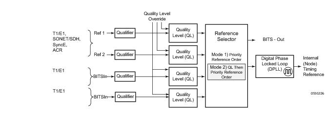
All settings of the signal characteristics for the BITS input applies to both ports. When the active CPM considers the BITS input as a possible reference, it will consider first the BITS input port on the active CPM followed the BITS input port on the standby CPM in that relative priority order. This relative priority order is in addition to the user definable ref-order. For example, a ref-order of ‘bits-ref1-ref2’ would actually be BITS in (active CPM) followed by BITS in (standby CPM) followed by ref1 followed by ref2. When ql-selection is enabled, then the QL of each BITS input port shall be viewed independently. The higher QL source shall be chosen.
The 7750 SR-c4 platform has a new CFM, there are two BITS input ports and two BITS output ports on this one module. These two ports are provided for BITS redundancy for the chassis. All settings of the signal characteristics for the BITS input applies to both ports. This includes the ql-override setting. When the CFM considers the BITS input as a possible reference, it will consider first the BITS input port “bits1” followed the BITS input port “bits2” in that relative priority order. This relative priority order is in addition to the user definable ref-order. For example, a ref-order of ‘bits-ref1-ref2’ would actually be “bits1” followed by “bits2” followed by ref1 followed by ref2. When ql-selection is enabled, then the QL of each BITS input port shall be viewed independently. The higher QL source shall be chosen.
The BITS output ports can be configured to provided either the an unfiltered recovered line clock from a SR/ESS port or the output of the central clock of the 7750 SR. The first case would be used if the port was connected to deliver an input reference directly to dedicated timing device in the facility (BITS or SASE device). The second case would be used to test the quality of the clocking used by the 7750 SR.
When QL selection mode is disabled, then the reversion setting controls when the central clock can re-select a previously failed reference.
The Table 22 shows the selection followed for two reference in both revertive and non-revertive modes:
 
 
Synchronization Status Messages (SSM)
SSM provides a mechanism to allow the synchronization distribution network to both determine the quality level of the clock sourcing a given synchronisation trail and to allow a network element to select the best of multiple input synchronization trails. Synchronization Status messages have been defined for various transport protocols including SONET/SDH, T1/E1, and Synchronous Ethernet, for interaction with office clocks, such as BITS or SSUs and embedded network element clocks.
SSM allows equipment to autonomously provision and reconfigure (by reference switching) their synchronization references, while helping to avoid the creation of timing loops. These messages are particularly useful to allow synchronization reconfigurations when timing is distributed in both directions around a ring.
 
DS1 Signals
DS1 signals can carry an indication of the quality level of the source generating the timing information using the SSM transported within the 1544 Kbit/s signal's Extended Super Frame (ESF) Data Link (DL) as specified in Recommendation G.704. No such provision is extended to SF formatted DS1 signals.
The format of the data link messages in ESF frame format is "0xxx xxx0 1111 1111", transmitted rightmost bit first. The six bits denoted "xxx xxx" contain the actual message; some of these messages are reserved for synchronization messaging. It takes 32 frames (such as 4 ms) to transmit all 16 bits of a complete DL.
 
E1 Signals
E1 signals can carry an indication of the quality level of the source generating the timing information using the SSM as specified in Recommendation G.704.
One of the Sa4 to Sa8 bits, (the actual Sa bit is for operator selection), is allocated for Synchronization Status Messages. To prevent ambiguities in pattern recognition, it is necessary to align the first bit (San1) with frame 1 of a G.704 E1 multiframe.
The numbering of the San (n = 4, 5, 6, 7, 8) bits. A San bit is organized as a 4-bit nibble San1 to San4. San1 is the most significant bit; San4 is the least significant bit.
The message set in San1 to San4 is a copy of the set defined in SDH bits 5 to 8 of byte S1.
 
SONET/SDH Signals
The SSM of SDH and SONET interfaces is carried in the S1 byte of the frame overhead. Each frame contains the four bit value of the QL.
 
DS3/E3
These signals are not required to be synchronous. However, it is acceptable for their clocking to be generated from a sychronization source. The SR/ESS shall permit E3/DS3 physical ports to be specified as a central clock input reference.
DS3/E3 signals do not support an SSM channel. QL-override should be used for these ports if ql-selection is enabled
 
Synchronous Ethernet
Traditionally, Ethernet-based networks employ the physical layer transmitter clock to be derived from an inexpensive +/-100ppm crystal oscillator and the receiver locks onto it. There is no need for long term frequency stability because the data is packetized and can be buffered. For the same reason there is no need for consistency between the frequencies of different links. However, you can derive the physical layer transmitter clock from a high quality frequency reference by replacing the crystal with a frequency source traceable to a primary reference clock. This would not effect the operation of any of the Ethernet layers, for which this change would be transparent. The receiver at the far end of the link would lock onto the physical layer clock of the received signal, and thus itself gain access to a highly accurate and stable frequency reference. Then, in a manner analogous to conventional hierarchical master-slave network synchronization, this receiver could lock the transmission clock of its other ports to this frequency reference and a fully time synchronous network could be established.
The advantage of using Synchronous Ethernet, compared with methods that rely on sending timing information in packets over an unclocked physical layer, is that it is not influenced by impairments introduced by the higher levels of the networking technology (packet loss, packet delay variation). Hence, the frequency accuracy and stability may be expected to exceed those of networks with unsynchronized physical layers.
Synchronous Ethernet allows operators to gracefully integrate existing systems and future deployments into conventional industry-standard synchronization hierarchy. The concept behind synchronous Ethernet is analogous to SONET/SDH system timing capabilities. It allows the operator to select any (optical) Ethernet port as a candidate timing reference. The recovered timing from this port will then be used to time the system (for example, the CPM will lock to this provisioned reference selection). The operator then could ensure that any of system output would be locked to a stable traceable frequency source.
If the port is a fixed copper Ethernet port and in 1000BASE-T mode of operation, there is a dependency on the 802.3 link timing for the Synchronous Ethernet functionality (refer to ITU-T G.8262). The 802.3 link Master-Slave timing states must align with the desired direction of Synchronous Ethernet timing flow. When a fixed copper Ethernet port is specified as an input reference for the node or when it is removed as an input reference for the node, an 802.3 link auto-negotiation is triggered to ensure the link timing aligns properly.
The SSM of Synchronous Ethernet uses an Ethernet OAM PDU that uses the slow protocol subtype. For a complete description of the format and processing see ITU-T G.8264
 
Clock Source Quality Level Definitions
The following clock source quality levels have been identified for the purpose of tracking network timing flow. These levels make up all of the defined network deployment options given in Recommendation G.803 and G.781. The Option I network is a network developed on the original European SDH model; whereas, the Option II network is a network developed on the North American SONET model.
In addition to the QL values received over SSM of an interface, the standards also define additional codes for internal use. These include the following:
Within the SR/ESS, there is also an internal quality level of QL-UNKNOWN. This is used to differentiate from a received QL-STU code but is equivalent for the purposes of QL selection.
 
 
2.  
3.  
4.  
5.  
6.  
7.  
9.  
10.  
11.  
12.  
15. QL-UNC
 
2.  
3.  
4.  
5.  
6.  
7.  
9.  
10.  
11.  
12.  
15. QL-UNC
Note: When the internal Quality level is in the range of 9 through 14, the output codes shown in Table 24, will only appear if QL selection is disabled. If ql-selection is enabled, then all of these internal states are changed to internal state 15 (Holdover) and the ssm value generated will reflect the holdover quality of the internal clock.
 
IEEE 1588v2 PTP
Precision Time Protocol (PTP) is a timing-over-packet protocol defined in the IEEE 1588v2 standard 1588 PTP 2008.
PTP may be deployed as an alternative timing-over-packet option to ACR. PTP provides the capability to synchronize network elements to a Stratum-1 clock or primary reference clock (PRC) traceable source over a network that may or may not be PTP-aware. PTP has several advantages over ACR. It is a standards-based protocol, has lower bandwidth requirements, can transport both frequency and time, and can potentially provide better performance.
PTP is supported on the following platforms provided the indicated hardware components are included:
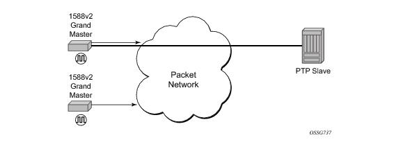
The 7750 SR supports the ordinary clock in slave or master mode or the boundary clock.When configured as an ordinary clock master, the 7750 SR7450 ESS can only provide frequency distribution using IEEE 1588v2. The boundary clock and ordinary clock slave can be used for both frequency and time distribution.
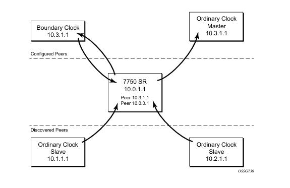
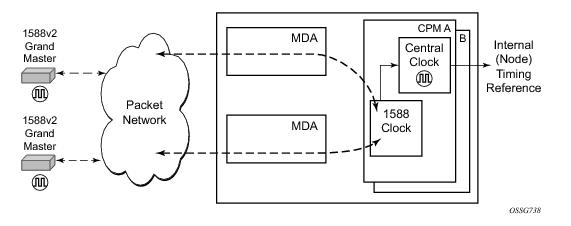
The 7750 SR communicates with peer IEEE 1588v2 clocks; see Figure 12. These peers can be ordinary clock masters, ordinary clock slaves, or boundary clocks. Each peer is identified by the IPv4 address to be used for communications between the two clocks.
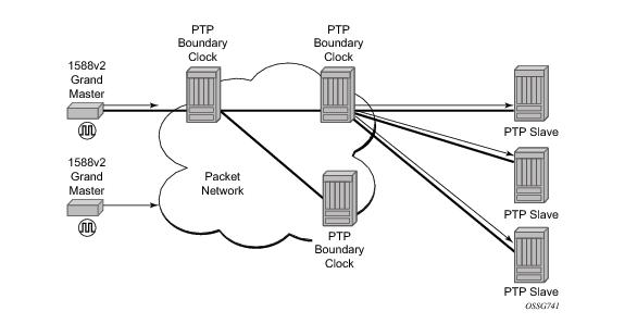
There are two types of peers: configured and discovered. The 7750 SR operating as an ordinary clock slave or as a boundary clock should have configured peers for each PTP neighbor clock from which it might accept synchronization information. The 7750 SR initiates unicast sessions with all configured peers. A 7750 SR operating as an ordinary clock master or boundary clock will accept unicast session requests from external peers. If the peer is not a configured peer, then it is considered a discovered peer. The 7750 SR can deliver synchronization information toward discovered peers.
Figure 12: Peer Clocks
The IEEE 1588v2 standard includes the concept of PTP profiles. These profiles are defined by industry groups or standards bodies that define how IEEE 1588v2 is to be used for a particular application.
7750 SRcurrently supports two profiles:
In both cases, communications between clocks utilize the Unicast communication procedures of the IEEE standard. The transport layer uses UDP/IPv4 encapsulation.
When a 7750 SR receives Announce messages from one or moreconfiguredpeers, it executes a Best Master Clock Algorithm (BMCA) to determine the state of communication between itself and the peers. The system uses the BMCA to create a hierarchical topology allowing the flow of synchronization information from the best source (the Grandmaster clock) out through the network to all boundary and slave clocks. Each profile has a dedicated BMCA.
If the profile setting for the clock is ieee1588-2008, the precedence order for the best master selection algorithm is as follows:
The 7750 SR sets its local parameters as follows:
If the profile setting for the clock is itu-telecom-freq (ITU G.8265.1 profile), the precedence order for the best master selection algorithm is:
The 7750 SR sets its local parameters as follows:
The ITU-T profile is for use in an environment with only ordinary clock masters and slaves for frequency distribution. The default profile should be used for all other cases.
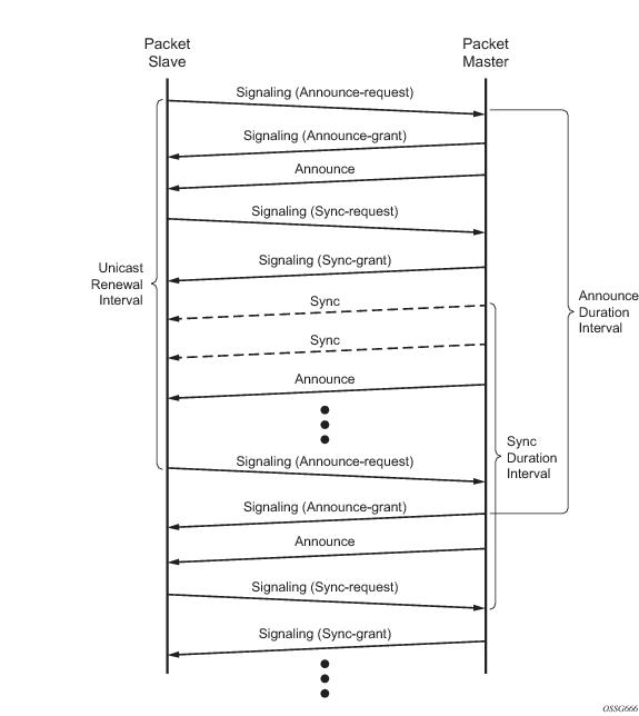
The 7750 SRcan support up to 70 simultaneous external peers. Up to 20 of these peers can be configured peers (possible Master or neighbor boundary clocks) and the remainder can only be discovered peers (slaves).These peers use the Unicast Negotiation procedures to request service from the 7750 SRclock.A neighbor boundary clock counts for two peers (both a configured and a discovered peer) toward the maximum limit.
Figure 13 shows the unicast negotiation procedure performed between a slave and a peer clock that is selected to be the master clock. The slave clock will request Announce messages from all peer clocks but only request Sync and Delay_Resp messages from the clock selected to be the master clock.
Figure 13: Messaging Sequence Between the PTP Slave Clock and PTP Master Clock
PTP Clock Synchronization
The IEEE 1588v2 standard allows for synchronization of the frequency and time from a master clock to one or more slave clocks over a packet stream. This packet-based synchronization can be over UDP/IP or Ethernet and can be multicast or unicast. Only IPv4 unicast mode with unicast negotiation is supported on the 7750 SR.
As part of the basic synchronization timing computation, a number of event messages are defined for synchronization messaging between the PTP slave clock and PTP master clock. A one-step or two-step synchronization operation can be used, with the two-step operation requiring a follow-up message after each synchronization message. . A 7750 SR configured as an ordinary master clock operates in one-step mode. A 7750 SR configured as an ordinary slave clock can communicate with both one-step and two-step master clocks.
During startup, the PTP port in selected into Slave state receives the synchronization messages from the external peer providing the master port service. Prior to any delay calculation, the delay is assumed to be zero. A drift compensation is activated after a number of synchronization message intervals occur.
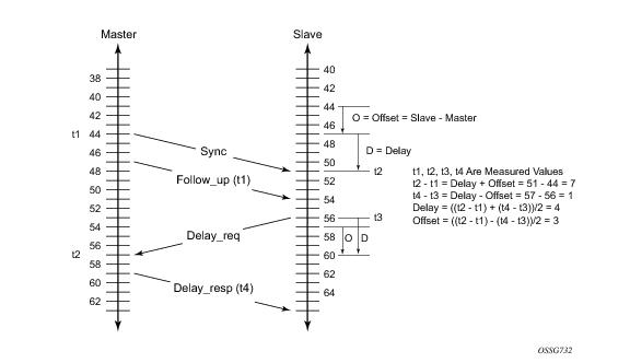
The basic synchronization timing computation between the PTP slave and PTP master is shown in Figure 14. This figure illustrates the offset of the slave clock referenced to the best master signal during startup.
Figure 14: PTP Slave and Master Time Synchronization Computation
When using IEEE 1588v2 for distribution of a frequency reference, the slave calculates a message delay from the master to the slave based on the timestamps exchanged. A sequence of these calculated delays will contain information of the relative frequencies of the master clock and slave clock but will have noise component related to the packet delay variation (PDV) experienced across the network. The slave must filter the PDV effects so as to extract the relative frequency data and then adjust the slave frequency to align with the master frequency.
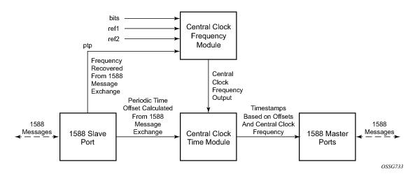
When using IEEE 1588v2 for distribution of time, the 7750 SR uses the four timestamps exchanged using the IEEE 1588v2 messages to determine the offset between the 7750 SR time base and the external master clock time base. The 7750 SR determines the offset adjustment and then in between these adjustments, the 7750 SR maintains the progression of time using the frequency from the central clock of the node. This allows time to be maintained using a BITS input source or a Synchronous Ethernet input source even if the IEEE 1588v2 communications fail. When using IEEE 1588v2 for time distribution, the central clock should at a minimum have the PTP input reference enabled.
Figure 15: Using IEEE 1588v2 For Time Distribution
 
Performance Considerations
Although IEEE 1588v2 can be used on a network that is not PTP-aware, the use of PTP-aware network elements (boundary clocks) within the packet switched network improves synchronization performance by reducing the impact of PDV between the grand master clock and the slave clock. In particular, when IEEE 1588v2 is used to distribute high accuracy time, such as for mobile base station phase requirements, then the network architecture requires the deployment of PTP awareness in every device between the Grandmaster and the mobile base station slave.
In addition, performance is also improved by the removal of any PDV caused by internal queuing within the boundary clock or slave clock. This is accomplished with hardware that is capable of detecting and time stamping the IEEE 1588v2 packets at the Ethernet interface. This capability is referred to as port-based time stamping.
NOTE: Support for port-based time stamping will be added to hardware modules over time. Consult the latest release notes for a list of 7750 SR modules capable of supporting port-based time stamping of IEEE 1588v2 messages.
 
Port Based Timestamping of PTP Messages
For ultimate performance, the 1588 packets should be timestamped at the ingress and egress of the 7750 SR. This then avoids any possible PDV that might be introduced between the port and the CPM. This capability to timestamp in the interface hardware is provided on a subset of the IMM and MDA assemblies of the 7750 SR. Refer to the release descriptions for the complete list.
In order for this to operate, the CPM, IOM, IMM, and MDAs must be running the firmware that supports the capability. The CPM firmware upgrade occurs automatically when the CPM card software is updated. Since upgrading of IOM, IMM, and MDA firmware is service impacting, this upgrade is not performed automatically on a soft reset of the MDA. The IOM/IMM firmware is upgraded when the IOM/IMM card is hard reset. The MDA firmware is programmed during system initialization, when the MDA is inserted, or when the MDA is hard reset via a clear mda or clear card command. However, when an MDA is soft reset via either a clear card soft command or during a major ISSU, the MDA firmware is not updated.
 
PTP Capabilities
PTP messages are supported via IPv4 unicast with a fixed IP header size. Table 27 describes the support message rates for slave and master states. The ordinary clock can be either in the slave or master state.
State and statistics data for each PTP peer are available to assist in the detection of failures or unusual situations.
 
PTP Ordinary Slave Clock For Frequency
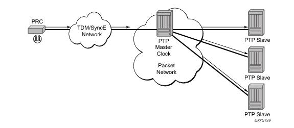
Traditionally, only clock frequency is required to ensure smooth transmission in a synchronous network. The PTP ordinary clock with slave capability on the 7750 SR provides another option to reference a Stratum-1 traceable clock across a packet switched network. The recovered clock can be referenced by the internal SSU and distributed to all slots and ports.Figure 16 shows a PTP ordinary slave clock network configuration.
Figure 16: Slave Clock
The PTP slave capability is implemented on the CPM, version 3 or later. The IEEE 1588v2 messages can ingress and egress the node on any line interface. Figure 17 shows the operation of an ordinary PTP clock in slave mode.
Figure 17: Ordinary Slave Clock Operation
 
PTP Ordinary Master Clock For Frequency
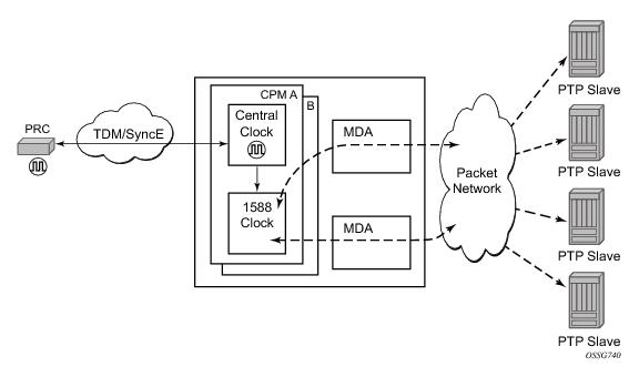
The 7750 SR supports the PTP ordinary clock in master mode. Normally, a IEEE 1588v2 grand master is used to support many slaves and boundary clocks in the network. In cases where only a small number of slaves and boundary clocks exist and only frequency is required, a PTP integrated master clock can greatly reduce hardware and management costs to implement PTP across the network. It also provides an opportunity to achieve better performance by placing a master clock closer to the edge of the network, as close to the slave clocks as possible. Figure 18 shows a PTP master clock network configuration.
Figure 18: PTP Master Clock
All packets are routed to their destination via the best route as determined in the route table; see Figure 19. It does not matter which ports are used to ingress and egress these packets (unless port based time stamping is enabled for higher performance).
Figure 19: Ordinary Master Clock Operation
 
PTP Boundary Clock for Frequency and Time
The 7750 SR supports boundary clock PTP devices in both master and slave states. IEEE 1588v2 can function across a packet network that is not PTP-aware; however, the performance may be unsatisfactory and unpredictable. PDV across the packet network varies with the number of hops, link speeds, utilization rates, and the inherent behavior of the routers. By using routers with boundary clock functionality in the path between the grand master clock and the slave clock, one long path over many hops is split into multiple shorter segments, allowing better PDV control and improved slave performance. This allows PTP to function as a valid timing option in more network deployments and allows for better scalability and increased robustness in certain topologies, such as rings. Boundary clocks can simultaneously function as a PTP slave of an upstream grand master (ordinary clock) or boundary clock, and as a PTP master of downstream slaves (ordinary clock) and/or boundary clocks.
 
Figure 20: Boundary Clock
In addition, the use of port based timestamping in every network element between the grandmaster and the end slave application is highly recommended for delivering time to meet one microsecond accuracies required of mobile applications.
The 7750 SR always uses the frequency output of the central clock to maintain the timebase within the node. The PTP reference into the central clock should always be enabled as an option if the 7750 is operating in 1588 Boundary Clock mode. This avoids the situation of the node entering holdover while propagating time with 1588.
 
PTP Clock Redundancy
The PTP module in the 7750 SR exists on the CPM. The PTP module on the standby CPM is kept synchronized to the PTP module on the active CPM. All sessions with external ptp peers are maintained over a CPM switchover.
System-Wide ATM Parameters
The atm-ping OAM loopback feature can be enabled on an ATM SAP for a period of time configured through the interval and the send-count parameters. When the ATM SAP terminates on IES or VPRN services, a failure of the loopback state machine does not bring down the Layer 3 interface. Only receiving AIS/RDI OAM cells or entering the AIS/RDI state brings down the Layer 3 interface.
The atm-ping OAM loopback feature can be also be enabled on a continuous basis on an ATM SAP terminating on IES or VPRN services. When the loopback state machine fails, the Layer 3 interface is brought down.
The ATM OAM loopback parameters must be first enabled and configured in the config>system> atm>oam context and then enabled in the IES or VPRN service interface SAP atm oam context.
Refer to the IES and VPRN sections of the 7750 OS Services Guide for further information.
Link Layer Discovery Protocol (LLDP)
The IEEE 802.1ab Link Layer Discovery Protocol (LLDP) is a uni-directional protocol that uses the MAC layer to transmit specific information related to the capabilities and status of the local device. Separately from the transmit direction, the LLDP agent can also receive the same kind of information for a remote device which is stored in the related MIBs.
LLDP itself does not contain a mechanism for soliciting specific information from other LLDP agents, nor does it provide a specific means of confirming the receipt of information. LLDP allows the transmitter and the receiver to be separately enabled, making it possible to configure an implementation so the local LLDP agent can either transmit only or receive only, or can transmit and receive LLDP information.
The information fields in each LLDP frame are contained in a LLDP Data Unit (LLDPDU) as a sequence of variable length information elements, that each include type, length, and value fields (known as TLVs), where:
Each LLDPDU contains four mandatory TLVs and can contain optional TLVs as selected by network management:
The chassis ID and the port ID values are concatenated to form a logical identifier that is used by the recipient to identify the sending LLDP agent/port. Both the chassis ID and port ID values can be defined in a number of convenient forms. Once selected however, the chassis ID/port ID value combination remains the same as long as the particular port remains operable.
A non-zero value in the TTL field of the time-to-live TLV tells the receiving LLDP agent how long all information pertaining to this LLDPDU’s identifier will be valid so that all the associated information can later be automatically discarded by the receiving LLDP agent if the sender fails to update it in a timely manner. A zero value indicates that any information pertaining to this LLDPDU’s identifier is to be discarded immediately.
Note that a TTL value of zero can be used, for example, to signal that the sending port has initiated a port shutdown procedure.
The end of a LLDPDU TLV marks the end of the LLDPDU.
The IEEE 802.1ab standard defines a protocol that:
Figure 21: LLDP Internal Architecture for a Network Node
Network operators must be able to discover the topology information in order to detect and address network problems and inconsistencies in the configuration. Moreover, standard-based tools can address the complex network scenarios where multiple devices from different vendors are interconnected using Ethernet interfaces.
Figure 22: Customer Use Example For LLDP
The example displayed in Figure 22 depicts a MPLS network that uses Ethernet interfaces in the core or as an access/handoff interfaces to connect to different kind of Ethernet enabled devices such as service gateway/routers, QinQ switches, DSLAMs or customer equipment.
IEEE 802.1ab LLDP running on each Ethernet interfaces in between all the above network elements may be used to discover the topology information.
 
Administrative Tasks
This section contains information to perform administrative tasks.
 
Configuring the Chassis Mode
Depending on the chassis type and IOM type, the following modes can be configured:
 
a: This mode corresponds to scaling and feature set associated with iom-20g.
b: This mode corresponds to scaling and feature set associated with iom-20g-b.
c: This mode corresponds to scaling and feature set associated with iom2-20g.
d: This mode corresponds to scaling and feature set associated with iom3-xp.
If the chassis mode is not explicitly provisioned in the configuration file, the chassis will come up in chassis mode a by default. The behavior for the IOMs is described in the following table:
To support a particular chassis-mode, all provisioned IOMs must meet the corresponding IOM level.
The chassis Mode corresponds to scaling and feature sets associated with a given card. The base mode is chassis mode A which supports all IOM card types.
IOM cards that are not compatible with more recent chassis modes will be put into an operationally failed state if the configuration chassis mode “force” option is used.
The force keyword forces an upgrade either from mode a to mode b or d with cards provisioned as iom-20g or from mode b to mode c with cards provisioned as iom-20g-b.
The ASAP MDA can only be configured if the IOM2-20g and IOM3-XP is provisioned.
Note that, if you are in chassis-mode d and configure an IOM type as iom2-20g and then downgrade to chassis-mode a or b (must specify force keyword), a warning appears about the IOM downgrade. In this case, the IOM`s provisioned type will downgrade to iom-20g-b. Once this is done, the ASAP MDA cannot be configured. The following message appears:
*A:138.120.214.68>config>system# chassis-mode b
MINOR: CHMGR #1009 Mode change requires force - card-type iom2-20g in slot 1 would 
change to iom-20g-b *A:138.120.214.68>config>system# chassis-mode b force
MINOR: CHMGR #1010 Can not change mode - mda m1-choc12-as-sfp in 10/1 not supported 
when card changes to iom-20g-b
If this is the desired behavior, for example, chassis-mode d is configured and IPv6 is running, you can then downgrade to chassis-mode a or b if you want to disable IPv6.
*A:ALA-48# show chassis
===============================================================================
Chassis Information
===============================================================================
    Name                          : ALA-48
    Type                          : 7750 SR-12
    Location                      : exit
    Coordinates                   : N 45 58 23, W 34 56 12
    CLLI code                     : abcdefg1234
    Number of slots               : 12
    Number of ports               : 246
    Critical LED state            : Off
    Major LED state               : Off
    Minor LED state               : Off
    Over Temperature state        : OK
    Base MAC address              : 14:30:ff:00:00:00
    Admin chassis mode            : d
    Oper chassis mode             : d
 
Hardware Data
    Part number                   : Sim Part#
    CLEI code                     : Sim CLEI
    Serial number                 : sim48
    Manufacture date              : 01012003
    Manufacturing string          : Sim MfgString sim48
    Manufacturing deviations      : Sim MfgDeviation sim48
    Time of last boot             : 2007/09/24 08:15:17
    Current alarm state           : alarm cleared
-------------------------------------------------------------------------------
Environment Information
...
===============================================================================
*A:ALA-48#
Saving Configurations
Whenever configuration changes are made, the modified configuration must be saved so they will not be lost when the system is rebooted.
Configuration files are saved by executing explicit command syntax which includes the file URL location to save the configuration file as well as options to save both default and non-default configuration parameters. Boot option file (BOF) parameters specify where the system should search for configuration and image files as well as other operational parameters during system initialization.
For more information about boot option files, refer to the Boot Option Files section of this manual.
Specifying Post-Boot Configuration Files
Two post-boot configuration extension files are supported and are triggered when either a successful or failed boot configuration file is processed. The boot-bad-exec and boot-good-exec commands specify URLs for the CLI scripts to be run following the completion of the boot-up configuration. A URL must be specified or no action is taken.
For example, after a configuration file is successfully loaded, the specified URL can contain a nearly identical configuration file with certain commands enabled or disabled, or particular parameters specified and according to the script which loads that file.
 
 
Network Timing
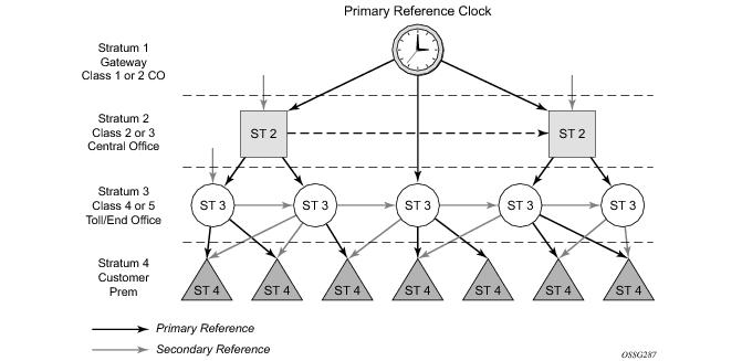
In Time Domain Multiplexed (TDM)-based networks (for example, SONET or SDH circuit- switched networks), the concept of network timing is used to prevent over-run or under-run issues where circuits are groomed (rebundled) and switched. Hardware exists in each node that takes a common clock derived from an internal oscillator, a specific receive interface or special BITS interface and provides it to each synchronous interface in the system. Usually, each synchronous interface is allowed to choose between using the chassis-provided clock or the clocking recovered from the received signal on the interface. The clocking is used to drive the transmit side of the interface. The appropriate configuration at each node which defines how interface clocking is handled must be considered when designing a network that has a centralized timing source so each interface is operating in a synchronous manner.
The effect of timing on a network is dependent on the nature of the type of traffic carried on the network. With bit-wise synchronous traffic (traditional circuit-based voice or video), non-synchronous transmissions cause a loss of information in the streams affecting performance. With packet-based traffic, the applications expect and handle jitter and latency inherent to packet-based networks. When a packet-based network is used to carry voice or video traffic, the applications use data compression and elasticity buffering to compensate for jitter and latency. The network itself relies on appropriate Quality of Service (QoS) definitions and network provisioning to further minimize the jitter and latency the application may experience.
 
Power Supplies
SR OS upports a power-supply command to configure the type and number of power supplies present in the chassis. The operational status of a power source is always displayed by the LEDs on the Control Processor/Switch Fabric Module (CP/SFM) front panel, but the power supply information must be explicitly configured in order for a power supply alarm to be generated if a power source becomes operationally disabled.
 
Automatic Synchronization
Use the CLI syntax displayed below to configure synchronization components relating to active-to-standby CPM switchover. In redundant systems, synchronization ensures that the active and standby CPMs have identical operational parameters, including the active configuration, CPM, and IOM images in the event of a failure or reset of the active CPM.
The force-switchover command forces a switchover to the standby CPM card.
To enable automatic synchronization, either the boot-env parameter or the config parameter must be specified. The synchronization occurs when the admin save or bof save commands are executed.
When the boot-env parameter of the synchronize command is specified, the bof.cfg, primary/secondary/tertiary configuration files (.cfg and .ndx), li, and ssh files are automatically synchronized. When the config parameter is specified, only the configuration files are automatically synchronized.
Synchronization also occurs whenever the BOF is modified and when an admin>save command is entered with no filename specified.
 
Boot-Env Option
The boot-env option enables a synchronization of all the files used in system initialization.
When configuring the system to perform this synchronization, the following occurs:
1.
The BOF used during system initialization is copied to the same compact flash on the standby CPM (in redundant systems).
Note: The synchronization parameters on the standby CPM are preserved.
2.
The primary, secondary, and tertiary images, (provided they are locally stored on the active CPM) are copied to the same compact flash on the standby CPM.
3.
 
Config Option
The config option synchronizes configuration files by copying the files specified in the active CPM BOF file to the same compact flash on the standby CPM.
 
Manual Synchronization
The admin redundancy synchronize command performs manual CPM synchronizations. The boot-env parameter synchronizes the BOF, image, and configuration files in redundant systems. The config parameter synchronizes only the configuration files in redundant systems.
 
Forcing a Switchover
The force-switchover now command forces an immediate switchover to the standby CPM card.
If the active and standby are not synchronized for some reason, users can manually synchronize the standby CPM by rebooting the standby by issuing the admin reboot standby command on the active or the standby CPM.
 
System Configuration Process Overview
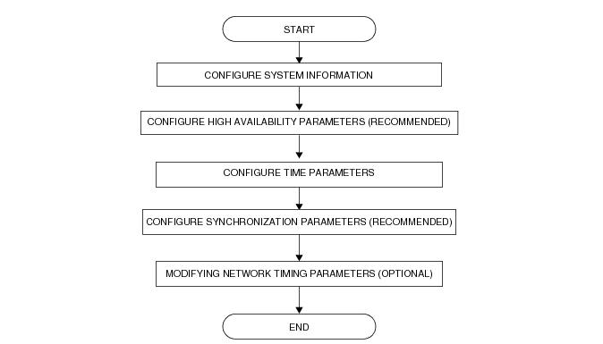
Figure 23 displays the process to provision basic system parameters.
Figure 23: System Configuration and Implementation Flow
Configuration Notes
This section describes system configuration caveats.
 
General
The system must be properly initialized and the boot loader and BOF files successfully executed in order to access the CLI.