For feedback, use the following:
ipd_online_feedback@alcatel-lucent.com
Table of Contents Previous Next Index PDF


Filter Policies
In This Chapter
The SROS supports filter policies for services and network interfaces (described in this chapter), subscriber management (integrated with service filter policies with the subscriber management specifics defined in the SROS Triple Play Guide), and CPM security and Management Interface (described in SROS Router Configuration Guide).
Topics in this chapter include:
ACL Filter Policy Overview
ACL Filter policies, also referred to as Access Control Lists (ACLs) or filter for short, are sets of ordered rules specifying packet match criteria and actions to be performed upon a match. Filters are applied to services or network ports to control network traffic into (ingress) or out of (egress) a service access port (SAP) or network. There are three main types of filter policies: IPv4, IPv6, and MAC filter policies. The same filter can be applied to ingress traffic, egress traffic, or both. Ingress filters affect only inbound traffic destined for the routing complex, and egress filters affect only outbound traffic sent from the routing complex.
Configuring an entity with a filter policy is optional. By default, there are no filters associated with services or interfaces, and therefore, all traffic is allowed on the ingress and egress interfaces. The filter must be explicitly created and associated. There are different types of filter policies as defined by the scope argument of the filter policy. An exclusive filter is intended to be used by a single SAP/interface, a template filter is intended to be shared by multiple SAP/interfaces in the system, and an embedded filter is intended to define common filter rules that can then be used (embedded) by other filters in the system. Filter policies are created with a unique filter ID, but each filter has also a unique filter name argument that can be defined once the filter policy has been created. Either filter ID or filter name can then be used throughout the system to manage filter policies and their associations.
On a Layer 2 SAP, either a single IP (v4 or v6) or a single MAC filter policy can be applied in a given direction. On a Layer 3 SAP and network interfaces, a single IP (v4 or v6) can be applied in a given direction. The ingress and egress direction policies can be same or different. For dual stack IPv4/IPv6 SAPs/interfaces, if both IPv4 and IPv6 filter policies are defined, the policy applied will be based on the outer IP header of the packet. Note that non-IP packets are not hitting an IP filter policy, so the default action in the IP filter policy will not apply to these packets.
 
 
Filter Policy Entities
A filter policy is applied to packets coming through the system, in the ascending order the entries are numbered in the policy. When a packet matches all the parameters specified in a filter entry’s match criteria, the system takes the specified action defined in that entry. If a packet does not match the entry parameters, the packet is compared to the next higher numerical filter entry, and so on. If the packet does not match any of the entries, the system executes the default action specified in the filter policy. Each filter policy is assigned a unique filter ID. Each filter policy is defined with:
Each filter entry contains:
 
Applying Filter Policies
Filter policies can be associated with the following entities:
 
 
ACL Filter Policy Scale
Release 11R4 introduces an enhanced flexibility in defining per service or per customer filter policies across services and interfaces that the router supports.
Prior to release 11.0, the number of filter policies supported in the system was equal to the number of filter policies supported by a single FlexPath on a line card. All policies would be downloaded to all line cards, regardless whether a policy was needed by a line card or not. Starting with Release 11.0R1, the number of filter policies that can be configured in a single system is now greater than the number of filter policies that can be used on a single FlexPath forwarding complex. The operator can manage the standard filter policies at a system-level (with system-wide policy identifiers) and SR-OS automatically maps and downloads policies to each FlexPath only as needed by services and interfaces configured on that FlexPath.
Statistics for filters aggregate all statistics across all FlexPaths that have a given filter entry active and will show zero (0) if a filter entry is not downloaded to any line card. The statistics are also reset to zero (0) when a given filter is removed from one of the line cards. When a filter is downloaded to a new line card as result of another service using that filter, the statistics continue incrementing. Figure 15 shows the new model for IPv4 ACL filter policies.
Figure 15: FlexPath ACL IPv4 Filter Policy Management Example
Assignment of filter policies to Interfaces, SAPs and SDPs is allowed up to the maximum number of filter policies supported per FlexPath (unchanged). If a maximum supported on a given FlexPath is breached, the configuration change to a filter policy is blocked. Due to a co-existence of dynamic filter policy entries in the system, an operator-configured filter policy may still fail to be installed in hardware later on. If that is the case, a trap will be raised for the impacted filter policies. It is recommended that the operator remove extra filter entries as operational conditions, such as an IOM reset for example may cause different filter entries to be activated when FlexPath limits are exceeded.
Note that a filter policy applied to a spoke, or to a SAP/Interface that resides on multiple line cards (for example, when a LAG or G.8032 rings with links on multiple cards are used), will be downloaded to all FlexPaths on all cards on which the SAP/interface resides.
Since only the active filter policies are downloaded to a given line card, counters for filter entries are available only for those filters that are downloaded to one or more line cards.
Match-list for Filter Policies
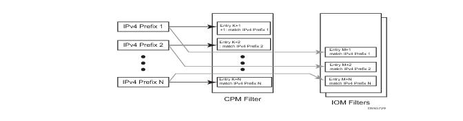
Figure 16 depicts an approach to implement logical OR on a list of matching criterion (IPv4 address prefixes in this example) in one or more filter policies prior to introduction of match list.
Figure 16: IOM/CPM Filter Policy using Individual Address Prefixes
An operator has to create one entry for each address prefix to execute a common action. Each entry defines a match on a unique address prefix from the list plus any other additional match criteria and the common action. If the same set of address prefixes needs to be used in another IOM or CPM filter policy, an operator again needs to create one entry for each address prefix of the list in those filter policies. Same procedure applies (not shown above) if another action needs to be performed on the list of the addresses within the same filter policy (when for example specifying different additional match criteria). This process can introduce large operational overhead, especially when a list contains many elements or/and needs to be reused multiple times across one or more filter policies.
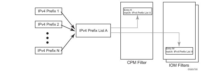
Match list for CPM and IOM filter policies are introduced to eliminate above operational complexity by simplifying the IOM and CPM filter policy management on a list of a match criterion. Instead of defining multiple filter entries in any given filter, an operator can now group same type of the matching criteria into a single filter match list, and then use that list as a match criterion value, thus requiring only single filter policy entry per each unique action. The same match list can be used in one or more IOM filter policies as well as CPM filter policies.
The match lists further simplify management and deployment of the policy changes. A change in a match-list content is automatically propagated across all policies employing that list in their match criteria, thus only a single configuration change is required to trigger policy changes when a list is used by multiple entries in one or more filter policies.
Figure 17 depicts how the IOM/CPM filter policy illustrated at the top of this section changes with a filter match list usage (using IPv4 address prefix list in this example).
Figure 17: IOM/CPM Filter Policy Using an Address Prefix Match List
Note: The hardware resource usage does not change whether filter match lists are used or whether operator creates multiple entries (each per one element of the list): however, a careful consideration must be given to how the lists are used to ensure only desired match permutations are created in a filter policy entry (especially when other matching criteria that are also lists or ranges are specified in the same entry). The system verifies that a new list element, for example, an IP address prefix, cannot be added to a given list or a list cannot be used by a new filter policy unless resources exist in hardware to implement the required filter policy (ies) that reference that list. If that is not the case, addition of a new element to the list or use of the list by another policy will fail.
Some use cases like those driven by dynamic policy changes, may result in acceptance of filter policy configuration changes that cannot be programmed in hardware because of the resource exhaustion. If that is the case, when attempting to program a filter entry that uses a match list(s), the operation will fail, the entry will be not programmed, and a notification of that failure will be provided to an operator.
Please refer to SROS Release Notes for what objects can be grouped into a filter match list for IOM and CPM filter policies.
 
Auto-generation of Filter-policy Address Prefix Match Lists
It is often desired to automatically update a filter policy when the configuration on a router changes. To allow such a touch-less filter policy management, SROS allows auto-generation of address prefixes for IPv4 or IPv6 address prefix match lists based on operator-configured criteria. When the configuration on a router changes, the match lists address prefixes are automatically updated and, in-turn, all filter policies (CPM or IOM) that use these match lists are automatically updated.
When using auto-generation of address prefixes inside an address prefix match list operators can:
Specify one or more regex expression matches against SROS router configuration per list.
Specify wildcard matches by specifying regex wildcard match expression (“.*”).
The following additional rules apply to auto-generated entries:
The following may apply to this feature:
If filter policy resources are not available for newly auto-generated address prefixes when a BGP configuration changes, new address-prefixes will not be added to impacted match lists or filter policies as applicable. An operator must free resources and change filter policy configuration or must change BGP configuration to recover from this failure.
 
Embedded Filter Support for ACL Filter Policies
When a large number of standard filter policies are configured in a system, a set of policies will often contain one or more common blocks of entries that define, for example, system-wide and/or service-wide security rules. Prior to introduction of the embedded filters, such common rules would have to be configured separately in each exclusive/template policy.
To simplify management of such common rules across multiple filter policies, operator can now use embedded filter policies. An embedded filter policy is a special type of a filter policy that cannot be deployed directly but instead is used to define a common filter policy rules that are then included in (embedded by) other filter policies in the system. Thanks to embedding, a common set of rules can now be defined and changed in a single place but deployed across multiple filter policies. The following main rules apply when embedding an embedded filter policy:
1.
2.
3.
4.
When embedding an embedded filter, an operator may wish to change or deactivate an embedded filter policy entry in one of the embedding filter, thus allowing for customizing of the common embedded filter policy rules by the embedding filter. This can be achieved by either defining an entry in the embedding filter that will match ahead of the embedded filter entry or by overwriting the embedded filter entry in the embedding filter.

For example: If embedded filter 99 has entry 20 that drops packets that match IP source address
src_address, and filter 200 embeds filter 99 at offset 100, then to deactivate the embedded entry 20, an operator could define an entry 120 (embedded entry number 20 + offset 100) in filter policy 200, that has the same match criteria and has either no action defined (this will deactivate the embedded entry and allow continued evaluation of filter policy 200), or has action forward defined (packets will match the new entry and will be forwarded instead of dropped, evaluation of filter policy 200 will stop).
5.
6.
7.
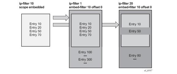
Figure 18 shows implementation of embedded filter policy using IPv4 ACL filter policy example with an embedded filter 10 being used to define common filter rules that are then embedded into filter 1 and 20 (with filter 20 overwriting rule at offset 50):
Figure 18: Embedded Filter Policy
 
 
Redirect Policies
SROS-based routers support redirect policies. Redirection policies are used to identify cache servers (or other redirection target destinations) and define health check test methods used to validate the ability for the destination to receive redirected traffic. This destination monitoring greatly diminishes the likelihood of a destination receiving packets it cannot process.
Redirection identifies packets to be redirected and specifies the method to reach the web cache server. Packets are identified by IPv4 filter entries. The redirection action is accomplished and supported with Policy Based Routing. Only IPv4 routed frames can be redirected. Bridged IP packets that match the entry criteria will not be redirected.
Redirection policies can contain multiple destinations. Each destination is assigned an initial or base priority describing its relative importance within the policy. The destination with the highest priority value is selected.
There are no default redirect policies. Each redirect policy must be explicitly configured and specified in an IPv4 filter entry.
To facilitate redirection based on a redirection policy, an IPv4 filter must be created and applied to the appropriate ingress IP interfaces where redirection is required. The entry criteria for the filter entry must specify a redirect policy to enable the appropriate IPv4 packets to be redirected from the normal IPv4 routing next hop. If packets do not meet any of the defined match criteria, then those packets are routed normally through the destination-based routing process.
The redirection policy is referenced within the action context for an IPv4 filter entry, binding the filter entry to the policy and the IPv4 destinations managed by the policy. The policy specifies the destination IPv4 address where the packets matching the filter entry will be redirected. When the policy determines the destination for packets matching the filter, the action on the filter entry is similar to provisioning that destination IPv4 address as an indirect next hop Policy Based Route (PBR) action.
 
Web Redirection (Captive Portal)
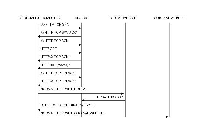
Web redirection policies can be configured on 7750 SR devices. Redirection policies were designed for testing purposes. The new redirection policy can now block a customer’s request from an intended recipient and force the customer to connect to the service’s portal server. 255 unique entries with http-redirect are allowed.
 
Traffic Flow
The following example provides a brief scenario of a customer connection with web redirection.
1.
2.
3.
4.
5.
6.
7.
Figure 19: Web Redirect Traffic Flow
Starred entries (*) are items the router performs masquerading as the destination, regardless of the destination IP address or type of service.
The following displays information that can optionally be added as variables in the portal URL (http-redirect url):
Note that the subscriber identification string is available only when used with subscriber management. Refer to the subscriber management section of the SROS Triple Play Guide and the SR OS Router Configuration Guide.
Since most web sites are accessed using the domain name the router allows either DNS queries or responds to DNS with the portal’s IP address.
 
ISID Filters
ISID filters are a type of MAC filters that allows filtering based on the ISID values rather than L2 criteria used by MAC filters of type "normal" or "vid". ISID filters can be deployed on iVPLS PBB SAPs and ePipe PBB SAPs in the following scenarios:
The MMRP usage of the mrp-policy ensures automatically that traffic using Group BMAC is not flooded between domains. However; there could be a small transitory periods when traffic originated from PBB BEB with unicast BMAC destination may be flooded in the BVPLS context as unknown unicast in the BVPLS context for both IVPLS and PBB Epipe. To restrict distribution of this traffic for local PBB services ISID filters can be deployed. The mac-filter configured with ISID match criterion can be applied to the same interconnect endpoint(s), BVPLS SAP or PW, as the mrp-policy to restrict the egress transmission any type of frames that contain a local ISID. The ISID filters will be applied as required on a per B-SAP or B-PW basis just in the egress direction.
The ISID match criteria are exclusive with any other criteria under mac-filter. A new mac-filter type attribute is defined to control the use of ISID match criteria and must be set to ISID to allow the use of ISID match criteria.
 
VID Filters
VID Filters are a type of MAC filters that extend the capability of current Ethernet Ports with null or default SAP tag configuration to match and take action on VID tags. Service delimiting tags (for example QinQ 1/1/1:10.20 or dot1q 1/1/1:10, where outer tag 10 and inner tags 20 are service delimiting) allow fine grain control of frame operations based on the VID tag. Service delimiting tags are exact match and are stripped from the frame as illustrated in Figure 20. Exact match or service delimiting Tags do not require VID filters. VID filters can only be used to match on frame tags that are after the service delimiting tags.
With VID Filters operators can choose to match VID tags for up to two tags on ingress or egress or both.
VID Filters add the capability to perform VID value filter policies on default tags (1/1/1:* or 1/1/1:x.*, or 1/1/1/:*.0), or null tags ( 1/1/1, 1/1/1:0 or 1/1/1:x.0). The matching is based on the port configuration and the SAP configuration.
In the industry the QinQ tags are often referred to as the C-VID (Customer VID) and S-VID (service VID). The terms outer tag and inner tag allow flexibility without having to refer to C-TAG and an S-TAG explicitly. The position of inner and outer tags is relative to the port configuration and SAP configuration. Matching of tags is allowed for up to the first two tags on a frame. Since service delimiting tags may be 0, 1 or 2 tags.
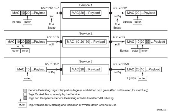
The meaning of inner and outer has been designed to be consistent for egress and ingress when the number of non service delimiting tags is consistent. Service 1 in Figure 20 shows a conversion from qinq to a single dot1q example where there is one non-service delimiting tag on ingress and egress. Service 2 shows a symmetric example with two non-service delimiting tags (plus and additional tag for illustration) to two non-service delimiting tags on egress. Service 3 illustrates single non-service delimiting tags on ingress and to two tags with one non-service delimiting tag on ingress and egress.
SAP-ingress QoS setting allows for MAC-criteria type VID which uses the VID filter matching capabilities QoS and VID Filters (moved to QoS guide) on page 313.
A VID filter entry can also be used as a debug or lawful intercept mirror source entry.
Figure 20: VID Filtering Examples
VID filters are available on Ethernet SAPs for Epipe, VPLS or I-VPLS including eth-tunnel and eth-ring services.
 
Arbitrary Bit Matching of VID Filters
In addition to matching an exact value, a VID filter mask allows masking any set of bits. The masking operation is ((value & vid-mask) = = (tag and vid-mask)). For example: A value of 6 and a mask of 7 would match all VIDs with the lower 3 bits set to 6. VID filters allow explicit matching of VIDs and matching of any bit pattern within the VID tag.
When using VID filters on SAPs only VID filters are allowed on this SAP. Filters of type normal and ISID are not allowed.
An additional check for the “0” VID tag may be required when using certain wild card operations. For example frames with no tags on null encapsulated ports will match a value of 0 in outer tag and inner tag because there are no tags in the frame for matching. If a zero tag is possible but not desired it can be explicitly filtered using exact match on “0” prior to testing other bits for “0”.
Note that configure>system>ethernet>new-qinq-untagged-sap is a special QinQ function for single tagged QinQ frames with a null second tag. Using this in combination with VID filters is not recommended. Note that the outer-tag is the only tag available for filtering on egress for frames arriving from MPLS SDPs or from PBB services even though additional tags may be carried transparently.
 
Port Group Configuration Example
 
Figure 21: Port Groups
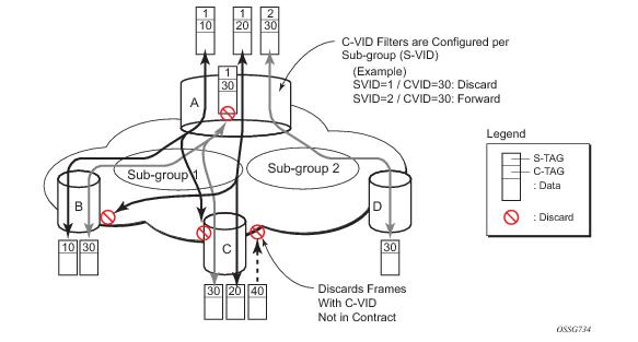
Figure 21 shows a customer use example where some VLANs are prevented from ingressing or egressing certain ports. In the example, port A sap 1/1/1:1.* would have a filter as shown below while port A sap 1/1/1:2.* would not.:
mac-filter 4 create
default-action forward
type vid
entry 1 create
match frame-type ethernet_II
outer-tag 30 4095
exit
action drop
exit
exit
 
Creating and Applying ACL Policies
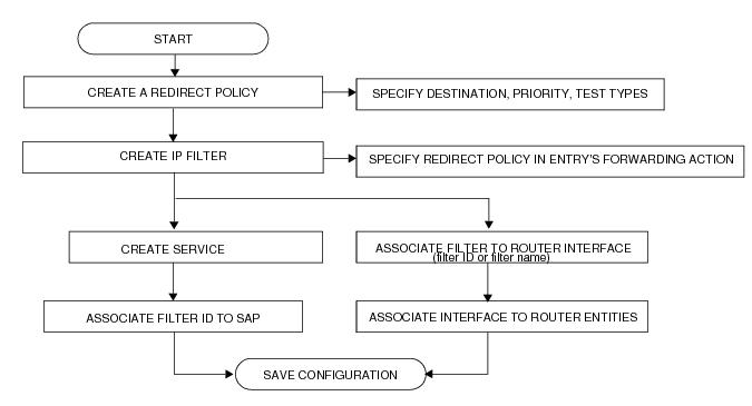
Figure 22 displays the process to create a redirect policy and to apply that policy to a service SAP or router interface.
Figure 22: Filter Creation and Implementation Flow
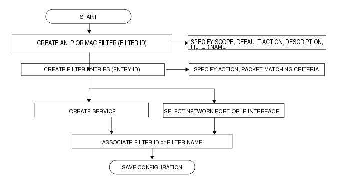
Figure 23 displays the process to create a filter policy and apply that policy to a service or network port.
Figure 23: Creating and Applying Filter Policies
 
Applying Filters
After filters are created, they can be applied to the following entities:
 
Applying a Filter to a SAP
During the SAP creation process, ingress and egress filters are selected from a list of qualifying IP and MAC filters. When ingress filters are applied to a SAP, packets received at the SAP are checked against the matching criteria in the filter entries. If the packet completely matches all criteria in an entry, the checking stops and the entry’s action is preformed. If the packet does not match any filter entries, the default filter action is applied.
When egress filters are applied to a SAP, packets received at the egress SAP are checked against the matching criteria in the filter entries. If the packet completely matches all criteria in an entry, the checking stops. If the packet does not match filter entries, the default filter action is applied.
Filters can be added or changed to an existing SAP configuration by modifying the SAP parameters. Filter policies are not operational until they are applied to a SAP and the service is enabled.
 
Applying a Filter to a Network Port a Network IP
An IP (v4 and/or IPv6) filter can be applied to a network port IP interface. Packets received on the interface are checked against the matching criteria in the filter entries. If the packet completely matches all criteria in an entry, the checking stops and the entry’s action is performed. If the packets do not match any filter entries, they are discarded or forwarded based on the default action specified in the policy.
 
Packet Match Criteria
SROS-based routers/switches support L2, L3 and L4 and above match criteria in IPv4, IPv6 and MAC filters. Type and scale of each criteria supported depends on the platform, please see your Alcatel-Lucent representative for further details. As few or as many match parameters can be specified as required, but all conditions within a single filter policy entry must be met in order for the packet to be considered a match and the specified action performed. Any match criteria will be ignored unless explicitly defined. The process stops when the first complete match is found with triggers execution of the action defined in the entry.
IP filter policy entry match criteria includes the following:
Match for the specified DSCP value against the Differentiated Services Code Point/Traffic Class field of the outer IPv4/IPv6 header of the packet.
src-port/dst-port — When protocol (IPv4) or next-header (IPv6) specifies TCP, UDP, or both for this entry, it matches against the Source Port Number/Destination Port Number of the outer IPv4/IPv6 header of the packet.
MAC filter policies match criteria includes the following:
snap-pid— Specifying an Ethernet IEEE 802.3 LLC SNAP PID allows the filter to match the two-byte protocol ID that follows the three-byte OUI field. The DSAP and mask accepts decimal and hex in the range of 0 to 65535.
 
DSCP Values
 
 
IP Option Values
 
Ordering Filter Entries
When entries are created, they should be arranged sequentially from the most explicit entry to the least explicit entry. Filter matching ceases when a packet matches an entry. The entry action is performed on the packet. To be considered a match, the packet must meet all the match criteria defined in the entry.
Packets are compared to entries in a filter policy in an ascending entry ID order. To reorder entries in a filter policy, edit the entry ID value; for example, to reposition entry ID 6 to a more explicit location, change the entry ID 6 value to entry ID 2 using the renum filter policy command.
When a filter consists of a single entry, the filter executes actions as follows:
If a filter policy contains two or more entries, packets are compared in ascending entry ID order (1, 2, 3 or 10, 20, 30, etc.):
 
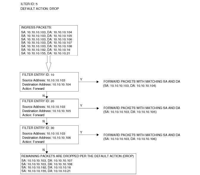
Figure 24 displays an example of several packets forwarded upon matching the filter criteria and several packets traversing through the filter entries and then dropped.
Figure 24: Filtering Process Example
Configuration Notes
The following information describes filter implementation caveats:
When a filter policy is configured, it should be defined as having either an exclusive scope for one-time use, or a template scope meaning that the filter can be applied to multiple SAPs.
 
MAC Filters
 
No 1

1
 
Note: When snap header is present, this is always set to AA-AA.


IP Filters
 
IPv6 Filters
 
Log Filter