For feedback, use the following:
ipd_online_feedback@alcatel-lucent.com
Table of Contents Previous Next Index PDF


IP Router Configuration
In This Chapter
This chapter provides information about commands required to configure basic router parameters.
Topics in this chapter include:
Configuring IP Router Parameters
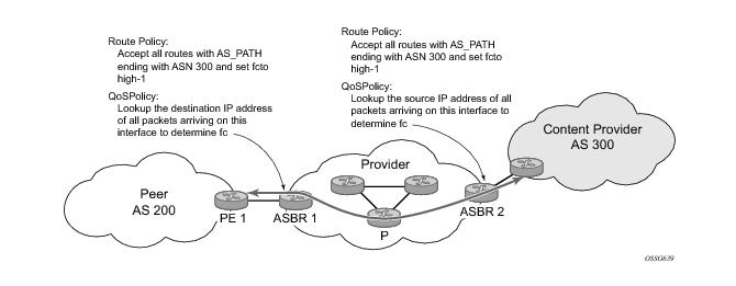
In order to provision services on an Alcatel-Lucent router, logical IP routing interfaces must be configured to associate attributes such as an IP address, port or the system with the IP interface.
A special type of IP interface is the system interface. A system interface must have an IP address with a 32-bit subnet mask. The system interface is used as the router identifier by higher-level protocols such as OSPF and BGP, unless overwritten by an explicit router ID.
The following router features can be configured:
Refer to 7750 SR OS Triple Play Guide for information about DHCP and support as well as configuration examples. on page 33
 
Interfaces
Alcatel-Lucent routers use different types of interfaces for various functions. Interfaces must be configured with parameters such as the interface type (network and system) and address. A port is not associated with a system interface. An interface can be associated with the system (loopback address).
 
Network Interface
A network interface (a logical IP routing interface) can be configured on one of the following entities:
 
Network Domains
In order to determine which network ports (and hence which network complexes) are eligible to transport traffic of individual SDPs, network-domain is introduced. This information is then used for the sap-ingress queue allocation algorithm applied to VPLS SAPs. This algorithm is optimized in such a way that no sap-ingress queues are allocated if the given port does not belong to the network-domain used in the given VPLS. In addition, sap-ingress queues will not be allocated towards network ports (regardless of the network-domain membership) if the given VPLS does not contain any SDPs.
Sap-ingress queue allocation takes into account the following aspects:
The implementation supports four network-domains within any given VPLS.
Network-domain configuration at the SDP level is ignored when the given SDP is used for Epipe, Ipipe, or Apipe bindings.
Network-domain configuration is irrelevant for Layer 3 services (Layer 3 VPN and/or IES service). It can be defined in the base routing context and associated only with network interfaces in this context. Network domains are not applicable to loopback and system interfaces.
The network-domain information will only be used for ingress VPLS sap queue-allocation. It will not be taken into account by routing during SDP setup. As a consequence, if the given SDP is routed through network interfaces that are not part of the configured network domain, the packets will be still forwarded, but their QoS and queuing behavior will be based on default settings. In addition, the packet will not appear in SAP stats.
There will be always one network-domain that exists with reserved name default. The interfaces will always belong to a default network-domain. It will be possible to assign given interface to different user-defined network-domains. The loopback and system interface will be also associated with the default network-domain at the creation. However, any attempt to associate such interfaces with any explicitly defined network-domain will be blocked at the CLI level as there is no benefit for that association.
Any SDP can be assigned only to one network domain. If none is specified, the system will assign the default network-domain. This means that all SAPs in VPLS will have queue reaching all fwd-complexes serving interfaces that belong to the same network-domains as the SDPs.
It is possible to assign/remove network-domain association of the interface/SDP without requiring deletion of the respective object.
 
System Interface
The system interface is associated with the network entity (such as a specific router or switch), not a specific interface. The system interface is also referred to as the loopback address. The system interface is associated during the configuration of the following entities:
The system interface is used to preserve connectivity (when routing reconvergence is possible) when an interface fails or is removed. The system interface is also referred to as the loopback address and is used as the router identifier. A system interface must have an IP address with a 32-bit subnet mask.
 
Unicast Reverse Path Forwarding Check (uRPF)
This section applies to the 7750-SR, 7710-SR, 7950-SR and the 7450-ESS.
uRPF helps to mitigate problems that are caused by the introduction of malformed or forged (spoofed) IP source addresses into a network by discarding IP packets that lack a verifiable IP source address. For example, a number of common types of denial-of-service (DoS) attacks, including smurf and tribe flood network (TFN), can take advantage of forged or rapidly changing source IP addresses to allow attackers to thwart efforts to locate or filter the attacks. For Internet service providers (ISPs) that provide public access, Unicast RPF deflects such attacks by forwarding only packets that have source addresses that are valid and consistent with the IP routing table. This action protects the network of the ISP, its customer, and the rest of the Internet.
uRPF is supported for both IPv4 and IPv6 on network and access. It is supported on any IP interface, including base router, IES, VPRN and subscriber group interfaces.
In strict mode, uRPF checks whether the incoming packet has a source address that matches a prefix in the routing table, and whether the interface expects to receive a packet with this source address prefix.
In loose mode, uRPF checks whether the packet has a source address with a corresponding prefix in the routing table; loose mode does not check whether the interface expects to receive a packet with a specific source address prefix.
Loose uRPF check is supported for ECMP, IGP shortcuts and VPRN MP-BGP routes. Packets coming from a source that matches any ECMP, IGP shortcut or VPRN MP-BGP route will pass the uRPF check even when the uRPF mode is set to strict mode on the incoming interface.
In the case of ECMP, this allows a packet received on an IP interface configured in strict URPF mode to be forwarded if the source address of the packet matches an ECMP route, even if the IP interface is not a next-hop of the ECMP route and even if the interface is not a member of any ECMP routes. The strict-no-ecmp uRPF mode may be configured on any interface which is known to not be a next-hop of any ECMP route. When a packet is received on this interface and the source address matches an ECMP route the packet is dropped by uRPF.
If there is a default route then this is included in the uRPF check, as follows:
If there is a default route:
Otherwise the uRPF check fails.
If the source IP address matches a discard/blackhole route, the packet is treated as if it failed uRPF check.
 
Creating an IP Address Range
An IP address range can be reserved for exclusive use for services by defining the config>router>service-prefix command. When the service is configured, the IP address must be in the range specified as a service prefix. If no service prefix command is configured, then no limitation exists.
Addresses in the range of a service prefix can be allocated to a network port unless the exclusive parameter is used. Then, the address range is exclusively reserved for services.
When defining a range that is a superset of a previously defined service prefix, the subset will be replaced with the superset definition. For example, if a service prefix exists for 10.10.10.0/24, and a new service prefix is configured as 10.10.0.0/16, then the old address (10.10.10.0/24) will be replaced with the new address (10.10.0.0/16).
When defining a range that is a subset of a previously defined service prefix, the subset will replace the existing superset, providing addresses used by services are not affected; for example, if a service prefix exists for 10.10.0.0/16, and a new service prefix is configured as 10.10.10.0/24, then the 10.10.0.0/16 entry will be removed, provided that no services are configured that use 10.10.x.x addresses other than 10.10.10.x.
 
QoS Policy Propagation Using BGP (QPPB)
This section discusses QPPB as it applies to VPRN, IES, and router interfaces. Refer to the Internet Enhanced Service section in the Services Guide and the IP Router Configuration section in the 7x50 SR OS Router Configuration Guide.
QoS policy propagation using BGP (QPPB) is a feature that allows a route to be installed in the routing table with a forwarding-class and priority so that packets matching the route can receive the associated QoS. The forwarding-class and priority associated with a BGP route are set using BGP import route policies. In the industry this feature is called QPPB, and even though the feature name refers to BGP specifically. On SR routers, QPPB is supported for BGP (IPv4, IPv6, VPN-IPv4, VPN-IPv6), RIP and static routes.
While SAP ingress and network QoS policies can achieve the same end result as QPPB, assigning a packet arriving on a particular IP interface to a specific forwarding-class and priority/profile based on the source IP address or destination IP address of the packet �the effort involved in creating the QoS policies, keeping them up-to-date, and applying them across many nodes is much greater than with QPPB. In a typical application of QPPB, a BGP route is advertised with a BGP community attribute that conveys a particular QoS. Routers that receive the advertisement accept the route into their routing table and set the forwarding-class and priority of the route from the community attribute.
 
QPPB Applications
There are two typical applications of QPPB:
1.
2. Traffic differentiation within a single domain, based on route characteristics.
 
Inter-AS Coordination of QoS Policies
The operator of an administrative domain A can use QPPB to signal to a peer administrative domain B that traffic sent to certain prefixes advertised by domain A should receive a particular QoS treatment in domain B. More specifically, an ASBR of domain A can advertise a prefix XYZ to domain B and include a BGP community attribute with the route. The community value implies a particular QoS treatment, as agreed by the two domains (in their peering agreement or service level agreement, for example). When the ASBR and other routers in domain B accept and install the route for XYZ into their routing table, they apply a QoS policy on selected interfaces that classifies traffic towards network XYZ into the QoS class implied by the BGP community value.
QPPB may also be used to request that traffic sourced from certain networks receive appropriate QoS handling in downstream nodes that may span different administrative domains. This can be achieved by advertising the source prefix with a BGP community, as discussed above. However, in this case other approaches are equally valid, such as marking the DSCP or other CoS fields based on source IP address so that downstream domains can take action based on a common understanding of the QoS treatment implied by different DSCP values.
In the above examples, coordination of QoS policies using QPPB could be between a business customer and its IP VPN service provider, or between one service provider and another.
 
Traffic Differentiation Based on Route Characteristics
There may be times when a network operator wants to provide differentiated service to certain traffic flows within its network, and these traffic flows can be identified with known routes. For example, the operator of an ISP network may want to give priority to traffic originating in a particular ASN (the ASN of a content provider offering over-the-top services to the ISP’s customers), following a certain AS_PATH, or destined for a particular next-hop (remaining on-net vs. off-net).
Figure 1 shows an example of an ISP that has an agreement with the content provider managing AS300 to provide traffic sourced and terminating within AS300 with differentiated service appropriate to the content being transported. In this example we presume that ASBR1 and ASBR2 mark the DSCP of packets terminating and sourced, respectively, in AS300 so that other nodes within the ISP’s network do not need to rely on QPPB to determine the correct forwarding-class to use for the traffic. Note however, that the DSCP or other COS markings could be left unchanged in the ISP’s network and QPPB used on every node.
Figure 1: Use of QPPB to Differentiate Traffic in an ISP Network
 
QPPB
There are two main aspects of the QPPB feature:
 
Associating an FC and Priority with a Route
This feature uses a command in the route-policy hierarchy to set the forwarding class and optionally the priority associated with routes accepted by a route-policy entry. The command has the following structure:
 fc fc-name [priority {low | high}]
The use of this command is illustrated by the following example:
config>router>policy-options
begin
community gold members 300:100
policy-statement qppb_policy
entry 10
from
protocol bgp
community gold
exit
action accept
fc h1 priority high
exit
exit
exit
commit
 
The fc command is supported with all existing from and to match conditions in a route policy entry and with any action other than reject, it is supported with next-entry, next-policy and accept actions. If a next-entry or next-policy action results in multiple matching entries then the last entry with a QPPB action determines the forwarding class and priority.
A route policy that includes the fc command in one or more entries can be used in any import or export policy but the fc command has no effect except in the following types of policies:
As evident from above, QPPB route policies support routes learned from RIP and BGP neighbors of a VPRN as well as for routes learned from RIP and BGP neighbors of the base/global routing instance.
QPPB is supported for BGP routes belonging to any of the address families listed below:
Note that a VPN-IP route may match both a VRF import policy entry and a BGP import policy entry (if vpn-apply-import is configured in the base router BGP instance). In this case the VRF import policy is applied first and then the BGP import policy, so the QPPB QoS is based on the BGP import policy entry.
This feature also introduces the ability to associate a forwarding-class and optionally priority with IPv4 and IPv6 static routes. This is achieved using the following modified versions of the static-route commands:
static-route {ip-prefix/prefix-length|ip-prefix netmask} [fc fc-name [priority {low | high}]] next-hop ip-int-name|ip-address
static-route {ip-prefix/prefix-length|ip-prefix netmask} [fc fc-name [priority {low | high}]] indirect ip-address
Priority is optional when specifying the forwarding class of a static route, but once configured it can only be deleted and returned to unspecified by deleting the entire static route.
 
Displaying QoS Information Associated with Routes
The following commands are enhanced to show the forwarding-class and priority associated with the displayed routes:
This feature uses a qos keyword to the show>router>route-table command. When this option is specified the output includes an additional line per route entry that displays the forwarding class and priority of the route. If a route has no fc and priority information then the third line is blank. The following CLI shows an example:
show router route-table [family] [ip-prefix[/prefix-length]] [longer | exact] [protocol protocol-name] qos
An example output of this command is shown below:
A:Dut-A# show router route-table 10.1.5.0/24 qos
===============================================================================
Route Table (Router: Base)
===============================================================================
Dest Prefix Type Proto Age Pref
Next Hop[Interface Name] Metric
QoS
-------------------------------------------------------------------------------
10.1.5.0/24 Remote BGP 15h32m52s 0
PE1_to_PE2 0
h1, high
-------------------------------------------------------------------------------
No. of Routes: 1
===============================================================================
A:Dut-A#


Enabling QPPB on an IP interface
To enable QoS classification of ingress IP packets on an interface based on the QoS information associated with the routes that best match the packets the qos-route-lookup command is necessary in the configuration of the IP interface. The qos-route-lookup command has parameters to indicate whether the QoS result is based on lookup of the source or destination IP address in every packet. There are separate qos-route-lookup commands for the IPv4 and IPv6 packets on an interface, which allows QPPB to enabled for IPv4 only, IPv6 only, or both IPv4 and IPv6. Note however, current QPPB based on a source IP address is not supported for IPv6 packets nor is it supported for ingress subscriber management traffic on a group interface.
The qos-route-lookup command is supported on the following types of IP interfaces:
When the qos-route-lookup command with the destination parameter is applied to an IP interface and the destination address of an incoming IP packet matches a route with QoS information the packet is classified to the fc and priority associated with that route, overriding the fc and priority/profile determined from the sap-ingress or network qos policy associated with the IP interface (see section 5.7 for further details). If the destination address of the incoming packet matches a route with no QoS information the fc and priority of the packet remain as determined by the sap-ingress or network qos policy.
Similarly, when the qos-route-lookup command with the source parameter is applied to an IP interface and the source address of an incoming IP packet matches a route with QoS information the packet is classified to the fc and priority associated with that route, overriding the fc and priority/profile determined from the sap-ingress or network qos policy associated with the IP interface. If the source address of the incoming packet matches a route with no QoS information the fc and priority of the packet remain as determined by the sap-ingress or network qos policy.
Currently, QPPB is not supported for ingress MPLS traffic on network interfaces or on CsC PE’-CE’ interfaces (config>service>vprn>nw-if).


QPPB When Next-Hops are Resolved by QPPB Routes
In some circumstances (IP VPN inter-AS model C, Carrier Supporting Carrier, indirect static routes, etc.) an IPv4 or IPv6 packet may arrive on a QPPB-enabled interface and match a route A1 whose next-hop N1 is resolved by a route A2 with next-hop N2 and perhaps N2 is resolved by a route A3 with next-hop N3, etc. In release 9.0 the QPPB result is based only on the forwarding-class and priority of route A1. If A1 does not have a forwarding-class and priority association then the QoS classification is not based on QPPB, even if routes A2, A3, etc. have forwarding-class and priority associations.
 
QPPB and Multiple Paths to a Destination
When ECMP is enabled some routes may have multiple equal-cost next-hops in the forwarding table. When an IP packet matches such a route the next-hop selection is typically based on a hash algorithm that tries to load balance traffic across all the next-hops while keeping all packets of a given flow on the same path. The QPPB configuration model described in Associating an FC and Priority with a Route allows different QoS information to be associated with the different ECMP next-hops of a route. The forwarding-class and priority of a packet matching an ECMP route is based on the particular next-hop used to forward the packet.
When Edge PIC [1] is enabled some BGP routes may have a backup next-hop in the forwarding table in addition to the one or more primary next-hops representing the equal-cost best paths allowed by the ECMP/multipath configuration. When an IP packet matches such a route a reachable primary next-hop is selected (based on the hash result) but if all the primary next-hops are unreachable then the backup next-hop is used. The QPPB configuration model described in Associating an FC and Priority with a Route allows the forwarding-class and priority associated with the backup path to be different from the QoS characteristics of the equal-cost best paths. The forwarding class and priority of a packet forwarded on the backup path is based on the fc and priority of the backup route.
 
QPPB and Policy-Based Routing
When an IPv4 or IPv6 packet with destination address X arrives on an interface with both QPPB and policy-based-routing enabled:
 
QPPB and GRT Lookup
Source-address based QPPB is not supported on any SAP or spoke SDP interface of a VPRN configured with the grt-lookup command.
 
QPPB Interaction with SAP Ingress QoS Policy
When QPPB is enabled on a SAP IP interface the forwarding class of a packet may change from fc1, the original fc determined by the SAP ingress QoS policy to fc2, the new fc determined by QPPB. In the ingress datapath SAP ingress QoS policies are applied in the first P chip and route lookup/QPPB occurs in the second P chip. This has the implications listed below:
The profile state of a SAP ingress packet that matches a QPPB route depends on the configuration of fc2 only. If the de-1-out-profile flag is enabled in fc2 and fc2 is not mapped to a priority mode queue then the packet will be marked out of profile if its DE bit = 1. If the profile state of fc2 is explicitly configured (in or out) and fc2 is not mapped to a priority mode queue then the packet is assigned this profile state. In both cases there is no consideration of whether or not fc1 was mapped to a priority mode queue.
The priority of a SAP ingress packet that matches a QPPB route depends on several factors. If the de-1-out-profile flag is enabled in fc2 and the DE bit is set in the packet then priority will be low regardless of the QPPB priority or fc2 mapping to profile mode queue, priority mode queue or policer. If fc2 is associated with a profile mode queue then the packet priority will be based on the explicitly configured profile state of fc2 (in profile = high, out profile = low, undefined = high), regardless of the QPPB priority or fc1 configuration. If fc2 is associated with a priority mode queue or policer then the packet priority will be based on QPPB (unless DE=1), but if no priority information is associated with the route then the packet priority will be based on the configuration of fc1 (if fc1 mapped to a priority mode queue then it is based on DSCP/IP prec/802.1p and if fc1 mapped to a profile mode queue then it is based on the profile state of fc1).
Table 2 summarizes these interactions.
 
 
Router ID
The router ID, a 32-bit number, uniquely identifies the router within an autonomous system (AS) (see Autonomous Systems (AS)). In protocols such as OSPF, routing information is exchanged between areas, groups of networks that share routing information. It can be set to be the same as the loopback address. The router ID is used by both OSPF and BGP routing protocols in the routing table manager instance.
There are several ways to obtain the router ID. On each router, the router ID can be derived in the following ways.
Define the value in the config>router router-id context. The value becomes the router ID.
Configure the system interface with an IP address in the config>router>interface ip-int-name context. If the router ID is not manually configured in the config>router router-id context, then the system interface acts as the router ID.
 
Autonomous Systems (AS)
Networks can be grouped into areas. An area is a collection of network segments within an AS that have been administratively assigned to the same group. An area’s topology is concealed from the rest of the AS, which results in a significant reduction in routing traffic.
Routing in the AS takes place on two levels, depending on whether the source and destination of a packet reside in the same area (intra-area routing) or different areas (inter-area routing). In intra-area routing, the packet is routed solely on information obtained within the area; no routing information obtained from outside the area can be used. This protects intra-area routing from the injection of bad routing information.
Routers that belong to more than one area are called area border routers. All routers in an AS do not have an identical topological database. An area border router has a separate topological database for each area it is connected to. Two routers, which are not area border routers, belonging to the same area, have identical area topological databases.
Autonomous systems share routing information, such as routes to each destination and information about the route or AS path, with other ASs using BGP. Routing tables contain lists of next hops, reachable addresses, and associated path cost metrics to each router. BGP uses the information and path attributes to compile a network topology.
 
Confederations
Configuring confederations is optional and should only be implemented to reduce the IBGP mesh inside an AS. An AS can be logically divided into smaller groupings called sub-confederations and then assigned a confederation ID (similar to an autonomous system number). Each sub-confederation has fully meshed IBGP and connections to other ASs outside of the confederation.
The sub-confederations have EBGP-type peers to other sub-confederations within the confederation. They exchange routing information as if they were using IBGP. Parameter values such as next hop, metric, and local preference settings are preserved. The confederation appears and behaves like a single AS.
Confederations have the following characteristics.
Routing within each sub-confederation is accomplished via IBGP.
EBGP is used to communicate between sub-confederations.
To migrate from a non-confederation configuration to a confederation configuration requires a major topology change and configuration modifications on each participating router. Setting BGP policies to select an optimal path through a confederation requires other BGP modifications.
There are no default confederations. Router confederations must be explicitly created. Figure 2 depicts a confederation configuration example.
Figure 2: Confederation Configuration
 
Proxy ARP
Proxy ARP is the technique in which a router answers ARP requests intended for another node. The router appears to be present on the same network as the “real” node that is the target of the ARP and takes responsibility for routing packets to the “real” destination. Proxy ARP can help nodes on a subnet reach remote subnets without configuring routing or a default gateway.
Typical routers only support proxy ARP for directly attached networks; the router is targeted to support proxy ARP for all known networks in the routing instance where the virtual interface proxy ARP is configured.
In order to support DSLAM and other edge like environments, proxy ARP supports policies that allow the provider to configure prefix lists that determine for which target networks proxy ARP will be attempted and prefix lists that determine for which source hosts proxy ARP will be attempted.
In addition, the proxy ARP implementation will support the ability to respond for other hosts within the local subnet domain. This is needed in environments such as DSL where multiple hosts are in the same subnet but can not reach each other directly.
Static ARP is used when an Alcatel-Lucent router needs to know about a device on an interface that cannot or does not respond to ARP requests. Thus, the configuration can state that if it has a packet with a certain IP address to send it to the corresponding ARP address. Use proxy ARP so the router responds to ARP requests on behalf of another device.
 
 
DHCP Relay
Refer to 7750 SROS Triple Play Guide for information about DHCP and support provided by the 7750 SR as well as configuration examples.
 
Internet Protocol Versions
The ­TiMOS implements IP routing functionality, providing support for IP version 4 (IPv4) and IP version 6 (IPv6). IP version 6 (RFC 1883, Internet Protocol, Version 6 (IPv6)) is a newer version of the Internet Protocol designed as a successor to IP version 4 (IPv4) (RFC-791, Internet Protocol). The changes from IPv4 to IPv6 effect the following categories:
   +-+-+-+-+-+-+-+-+-+-+-+-+-+-+-+-+-+-+-+-+-+-+-+-+-+-+-+-+-+-+-+-+
|Version| Prio. | Flow Label |
+-+-+-+-+-+-+-+-+-+-+-+-+-+-+-+-+-+-+-+-+-+-+-+-+-+-+-+-+-+-+-+-+
| Payload Length | Next Header | Hop Limit |
+-+-+-+-+-+-+-+-+-+-+-+-+-+-+-+-+-+-+-+-+-+-+-+-+-+-+-+-+-+-+-+-+
| |
+ +
| |
+ Source Address +
| |
+ +
| |
+-+-+-+-+-+-+-+-+-+-+-+-+-+-+-+-+-+-+-+-+-+-+-+-+-+-+-+-+-+-+-+-+
| |
+ +
| |
+ Destination Address +
| |
+ +
| |
+-+-+-+-+-+-+-+-+-+-+-+-+-+-+-+-+-+-+-+-+-+-+-+-+-+-+-+-+-+-+-+-+
Figure 3: IPv6 Header Format
 
 
IPv6 Applications
Examples of the IPv6 applications supported by the ­TiMOS include:
IPv6 Internet exchange peering — Figure 4 shows an IPv6 Internet exchange where multiple ISPs peer over native IPv6.
Figure 4: IPv6 Internet Exchange
 
 
IPv6 transit services — Figure 5 shows IPv6 transit provided by an ISP.
Figure 5: IPv6 Transit Services
 
IPv6 services to enterprise customers and home users — Figure 6 shows IPv6 connectivity to enterprise and home broadband users.
Figure 6: IPv6 Services to Enterprise Customers and Home Users
 
IPv6 over IPv4 is an automatic tunnel method that gives a prefix to the attached IPv6 network. Figure 7 shows IPv6 over IPv4 tunneling to transition from IPv4 to IPv6.
Figure 7: IPv6 over IPv4 Tunnels
DNS
The DNS client is extended to use IPv6 as transport and to handle the IPv6 address in the DNS AAAA resource record from an IPv4 or IPv6 DNS server. An assigned name can be used instead of an IPv6 address since IPv6 addresses are more difficult to remember than IPv4 addresses.
 
IPv6 Provider Edge Router over MPLS (6PE)
6PE allows IPv6 domains to communicate with each other over an IPv4 MPLS core network. This architecture requires no backbone infrastructure upgrades and no re-configuration of core routers, because forwarding is purely based on MPLS labels. 6PE is a cost effective solution for IPv6 deployment.
Figure 8: Example of a 6PE Topology within One AS
 
6PE Control Plane Support
The 6PE MP-BGP routers support:
 
6PE Data Plane Support
The ingress 6PE router can push two MPLS labels to send the packets to the egress 6PE router. The top label is an LDP label used to reach the egress 6PE router. The bottom label is advertised in MP-BGP by the remote 6PE router. Typically, the IPv6 explicit null (value 2) label is used but an arbitrary value can be used when the remote 6PE router is from a vendor other than Alcatel-Lucent.
The egress 6PE router pops the top LDP tunnel label. It sees the IPv6 explicit null label, which indicates an IPv6 packet is encapsulated. It also pops the IPv6 explicit null label and performs an IPv6 route lookup to find out the next hop for the IPv6 packet.
 
Bi-directional Forwarding Detection
Bi-directional Forwarding Detection (BFD) is a light-weight, low-overhead, short-duration detection of failures in the path between two systems. If a system stops receiving BFD messages for a long enough period (based on configuration) it is assumed that a failure along the path has occurred and the associated protocol or service is notified of the failure.
BFD can provide a mechanism used for liveness detection over any media, at any protocol layer, with a wide range of detection times and overhead, to avoid a proliferation of different methods.
SR OS supports asynchronous and on deman modes of BFD in which BFD messages are set to test the path between systems.
If multiple protocols are running between the same two BFD endpoints then only a single BFD session is established, and all associated protocols will share the single BFD session.
In addition to the typical asynchronous mode, there is also an echo function defined within RFC 5880, Bi-directional Forwarding Detection, that allows either of the two systems to send a sequence of BFD echo packets to the other system, which loops them back within that system’s forwarding plane. If a number of these echo packets are lost then the BFD session is declared down.
 
BFD Control Packet
The base BFD specification does not specify the encapsulation type to be used for sending BFD control packets. Instead it is left to the implementers to use the appropriate encapsulation type for the medium and network. The encapsulation for BFD over IPv4 and IPv6 networks is specified in draft-ietf-bfd-v4v6-1hop-04.txt, BFD for IPv4 and IPv6 (Single Hop). This specification requires that BFD control packets be sent over UDP with a destination port number of 3784 and the source port number must be within the range 49152 to 65535.
In addition, the TTL of all transmitted BFD packets must have an IP TTL of 255. All BFD packets received must have an IP TTL of 255 if authentication is not enabled. If authentication is enabled, the IP TTL should be 255 but can still be processed if it is not (assuming the packet passes the enabled authentication mechanism).
If multiple BFD sessions exist between two nodes, the BFD discriminator is used to de-multiplex the BFD control packet to the appropriate BFD session.
 
Control Packet Format
The BFD control packet has 2 sections, a mandatory section and an optional authentication section.
0                   1                   2                   3
0 1 2 3 4 5 6 7 8 9 0 1 2 3 4 5 6 7 8 9 0 1 2 3 4 5 6 7 8 9 0 1
+-+-+-+-+-+-+-+-+-+-+-+-+-+-+-+-+-+-+-+-+-+-+-+-+-+-+-+-+-+-+-+-+
|Vers | Diag |Sta|P|F|C|A|D|R| Detect Mult | Length |
+-+-+-+-+-+-+-+-+-+-+-+-+-+-+-+-+-+-+-+-+-+-+-+-+-+-+-+-+-+-+-+-+
| My Discriminator |
+-+-+-+-+-+-+-+-+-+-+-+-+-+-+-+-+-+-+-+-+-+-+-+-+-+-+-+-+-+-+-+-+
| Your Discriminator |
+-+-+-+-+-+-+-+-+-+-+-+-+-+-+-+-+-+-+-+-+-+-+-+-+-+-+-+-+-+-+-+-+
| Desired Min TX Interval |
+-+-+-+-+-+-+-+-+-+-+-+-+-+-+-+-+-+-+-+-+-+-+-+-+-+-+-+-+-+-+-+-+
| Required Min RX Interval |
+-+-+-+-+-+-+-+-+-+-+-+-+-+-+-+-+-+-+-+-+-+-+-+-+-+-+-+-+-+-+-+-+
| Required Min Echo RX Interval |
Figure 9: Mandatory Frame Format
 
 
BFD for RSVP-TE
BFD will notify RSVP-TE if the BFD session goes down, in addition to notifying other configured BFD enabled protocols (for example, OSPF, IS-IS and PIM). This notification will then be used by RSVP-TE to begin the reconvergence process. This greatly accelerates the overall RSVP-TE response to network failures.
All encapsulation types supporting IPv4 and IPv6 is supported as all BFD packets are carried in IPv4 and IPv6 packets; this includes Frame Relay and ATM.
BFD is supported on the following interfaces:
Channelized interfaces (PPP, HDLC, FR and ATM) on ASAP (priority 1) and channelized MDAs (Priority 2) including link bundles and IMA
 
Echo Support
Echo support for BFD calls for the support of the echo function within BFD. By supporting BFD echo, the router loops back received BFD echo messages to the original sender based on the destination IP address in the packet.
The echo function is useful when the local router does not have sufficient CPU power to handle a periodic polling rate at a high frequency. As a result, it relies on the echo sender to send a high rate of BFD echo messages through the receiver node, which is only processed by the receiver’s forwarding path. This allows the echo sender to send BFD echo packets at any rate.
Note that the SR-OS router does not support the sending of echo requests, only the response to echo requests.
 
BFD Support for BGP
This feature enhancement allows BGP peers to be associated with the BFD session. If the BFD session failed, then BGP peering will also be torn down.
 
Centralized BFD
The following applications of centralized BFD require BFD to run on the SF/CPM.
 
IES Over Spoke SDP
One application for a central BFD implementation is so BFD can be supported over spoke SDPs used to inter-connection IES or VPRN interfaces. When there are spoke SDPs for inter-connections over an MPLS network between two routers, BFD is used to speed up failure detections between nodes so re-convergence of unicast and multicast routing information can begin as quickly as possible.
The MPLS LSP associated with the spoke SDP can enter or egress from multiple interfaces on the box. BFD for these types of interfaces can not exist on the IOM itself.
 
Figure 10: BFD for IES/VPRN over Spoke SDP
 
BFD Over LAG and VSM Interfaces
A second application for a central BFD implementation is so BFD can be supported over LAG or VSM interface. This is useful where BFD is not used for link failure detection but instead for node failure detection. In this application, the BFD session can run between the IP interfaces associated with the LAG or VSM interface, but there is only one session between the two nodes. There is no requirement for the message flow to across a certain link, or VSM, to get to the remote node.
Figure 11: BFD over LAG
Figure 12:  
 
Aggregate Next Hop
This feature adds the ability to configure an indirect next-hop for aggregate routes. The indirect next-hop specifies where packets will be forwarded if they match the aggregate route but not a more-specific route in the IP forwarding table.
Process Overview
The following items are components to configure basic router parameters.
Confederation — (Optional) Creates confederation autonomous systems within an AS to reduce the number of IBGP sessions required within an AS.
Configuration Notes
The following information describes router configuration caveats.