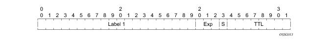
As described in RFC 3032, MPLS Label Stack Encoding, the label stack is represented as a sequence of label stack entries. Each label stack entry is represented by 4 octets.
Figure 1 displays the label placement in a packet.
Packets traveling along an LSP (see Label Switching Routers ) are identified by its label, the 20-bit, unsigned integer. The range is 0 through 1,048,575. Label values 0-15 are reserved and are defined below as follows:
The router uses labels for MPLS, RSVP-TE, and LDP, as well as packet-based services such as VLL and VPLS.
|
•
|
Label values 18,432 through 262,143 (131,071 in chassis modes lower than D) are assigned dynamically by RSVP, LDP, and BGP control planes for both MPLS LSP and service labels.
|
|
•
|
Label values 262,144 (131,072 in chassis modes lower than D) through 1,048,575 are reserved for future use.
|
The LSP ping interval is configured using the lsp-ping-interval command under the
bfd context for the LSP or LSP primary path.
config
router
bfd
bfd-template name
transmit-interval transmit-interval
receive-interval receive-interval
echo-receive echo-interval
multiplier multiplier
type cpm-np
exit
Note that network processor BFD is not supported for LSPs. Furthermore, the minimum supported receive or transmit timer interval is 1 second. Therefore, an error will be generated if a user tries to bind a bfd-template with the ‘
type cpm-np’ command or any unsupported transmit or receive interval value to an LSP. An error will also be generated as user attempts to commit changes to a BFD template that is already bound to an LSP where the new values are invalid for lsp-bfd.
The config>router>lsp-bfd command enables support for LSP BFD and allows an upper limit to the number of supported sessions at the tail end node for LSPs, where it is disabled by default. This is useful because BFD resources are shared among applications using BFD, so a user may wish to set an upper limit to ensure that a certain number of BFD sessions are reserved for other applications. This is important at the tail end of LSPs where no per-LSP configuration context exists.
LSP BFD is enabled or disabled on a node-wide basis using the bfd-sessions max-limit command under the
config>router>lsp-bfd context. This command also enables the maximum number of LSP BFD sessions that can be established at the tail end of LSPs to be limited.
The default is disabled. The max-limit parameter specifies the maximum number of LSP BFD sessions that the system will allow to be established at the tail end of LSPs.
config
router
mpls
lsp xyz
bfd
[no] bfd-template name
[no] bfd-enable
exit
The bfd-template provides the control packet timer values for the BFD session to use at the LSP head end. Since there is no LSP configuration at the tail end of an RSVP LSP, the BFD state machine at the tail end will initially use system-wide default parameters (the timer values are: min-tx: 1sec, min-rx: 1sec). The head end will then attempt to adjust the control packet timer values when it transitions to the INIT state.
config
router
mpls
lsp <xyz>
primary path-name
bfd
[no] bfd-template name
[no] bfd-enable
exit
Config
router
mpls
lsp-template template-name {mesh-p2p | one-hop-p2p}
bfd
[no] bfd-template name
[no] bfd-enable
exit
The ingress LER switches to the standby LSP path. If the primary LSP path is repaired subsequently at the PLR, the LSP will switch back to the primary path. If the standby goes down, the LSP is switched back to the primary, even though it is still on the detour at the PLR. If the primary goes down at the ingress while the LSP is on the standby, the detour at the ingress is cleaned up and for one-to-one detours a “path tear” is sent for the detour path. In other words, the detour at the ingress does not protect the standby. If and when the primary LSP is again successfully re-signaled, the ingress detour state machine will be restarted.
In prior releases, the router
implemented dynamic bypass tunnels as per RFC 4090, Fast Reroute Extensions to RSVP-TE for LSP Tunnels. When an LSP is signaled and the local protection flag is set in the session_attribute object and/or the FRR object in the path message indicates that facility backup is desired, the PLR will establish a bypass tunnel to provide node and link protection. If a bypass LSP which merges in a downstream node with the protected LSP exist, and if this LSP satisfies the constraints in the FRR object, then this bypass tunnel is selected.
With the manual bypass feature, an LSP can be pre-configured from a PLR which will be used exclusively for bypass protection. When a path message for a new LSP requests bypass protection, the node will first check if a manual bypass tunnel satisfying the path constraints exists. If one is found, it will be selected. If no manual bypass tunnel is found, the router will dynamically signal a bypass LSP in the default behavior. Users can disable the dynamic bypass creation on a per node basis using the CLI.
A maximum of 1000 associations of primary LSP paths can be made with a single manual bypass by default. The max-bypass-associations integer command increases the number of associations. If dynamic bypass creation is disabled on the node, it is recommended to configure additional manual bypass LSPs to handle the required number of associations.
The PLR uses the following rules to select a bypass LSP among multiple manual and dynamic bypass LSPs at the time of establishment of the primary LSP path or when searching for a bypass for a protected LSP which does not have an association with a bypass tunnel:
|
1.
|
The MPLS/RSVP task in the PLR node checks if an existing manual bypass satisfies the constraints. If the path message for the primary LSP path indicated node protection desired, which is the default LSP FRR setting at the head end node, MPLS/RSVP task searches for a node-protect’ bypass LSP. If the path message for the primary LSP path indicated link protection desired, then it searches for a link-protect bypass LSP.
|
|
5.
|
If the path message for the primary LSP path indicated node protection desired, and no manual bypass was found after Step 1, and/or no dynamic bypass LSP was found after one attempt of performing Step 3, the MPLS/RSVP task will repeat Steps 1 to 3 looking for a suitable link-protect bypass LSP. If none are found, the primary LSP will have no protection and the PLR node must clear the “local protection available” flag in the IPv4 address sub-object of the RRO starting in the next Resv refresh message it sends upstream. Node protection will continue to be attempted using a background re-evaluation process.
|
|
6.
|
If the path message for the primary LSP path indicated link protection desired, and no manual bypass was found after step 1, and/or no dynamic bypass LSP was found after performing Step 3, the primary LSP will have no protection and the PLR node must clear the “local protection available” flag in the IPv4 address sub-object of the RRO starting in the next RESV refresh message it sends upstream. The PLR will not search for a node-protect’ bypass LSP in this case.
|
If the user disables dynamic-bypass tunnels on a node while dynamic bypass tunnels were activated and were passing traffic, traffic loss will occur on the protected LSP. Furthermore, if no manual bypass exist that satisfy the constraints of the protected LSP, the LSP will remain without protection.
If the user configures a bypass tunnel on node B and dynamic bypass tunnels have been disabled, LSPs which have been previously signaled and which were not associated with any manual bypass tunnel, for example, none existed, will be associated with the manual bypass tunnel if suitable. The node checks for the availability of a suitable bypass tunnel for each of the outstanding LSPs every time a RESV message is received for these LSPs.
If the user configures a bypass tunnel on node B and dynamic bypass tunnels have not been disabled, LSPs which have been previously signaled over dynamic bypass tunnels will not automatically be switched into the manual bypass tunnel even if the manual bypass is a more optimized path. The user will have to perform a make before break at the head end of these LSPs.
If the manual bypass goes into the down state in node B and dynamic bypass tunnels have been disabled, node B (PLR) will clear the “protection available” flag in the RRO IPv4 sub-object in the next RESV refresh message for each affected LSP. It will then try to associate each of these LSPs with one of the manual bypass tunnels that are still up. If it finds one, it will make the association and set again the “protection available” flag in the next RESV refresh message for each of these LSPs. If it could not find one, it will keep checking for one every time a RESV message is received for each of the remaining LSPs. When the manual bypass tunnel is back UP, the LSPs which did not find a match will be associated back to this tunnel and the protection available flag is set starting in the next RESV refresh message.
If the manual bypass goes into the down state in node B and dynamic bypass tunnels have not been disabled, node B will automatically signal a dynamic bypass to protect the LSPs if a suitable one does not exist. Similarly, if an LSP is signaled while the manual bypass is in the down state, the node will only signal a dynamic bypass tunnel if the user has not disabled dynamic tunnels. When the manual bypass tunnel is back into the UP state, the node will not switch the protected LSPs from the dynamic bypass tunnel into the manual bypass tunnel.
The MPLS Fast Re-Route (FRR) functionality enables PLRs to be aware of the missing node protection and lets them regularly probe for a node-bypass. The following describes an LSP scenario:
Since LSP 1 had requested node protection, but due to lack of any available path, it could only obtain link protection. Therefore, every 60 seconds the PLR for LSP 1 will search for a new path that might be able to provide node protection. Once P_4 is back online and such a path is available, A new bypass tunnel will be signalled and LSP 1 will get associated with this new bypass tunnel.
The switchover time is measured from the time the control plane detected the failure of the interface or neighbor/next-hop to the time the IOM completed the reprogramming of all the impacted ILM or service records in the data path. This includes the time it takes for the control plane to send a down notification to all IOMs to request a switch to the backup NHLFE.
When an LSP is first established, the bandwidth reserved along its primary path is controlled by the bandwidth parameter in the config>router>mpls>lsp>primary context, whether or not the LSP has auto-bandwidth enabled, while the bandwidth reserved along a secondary path is controlled by the bandwidth parameter in the config>router>mpls>lsp>secondary context. When auto-bandwidth is enabled and a trigger occurs, the system will attempt to change the bandwidth of the LSP to a value between min-bandwidth and max-bandwidth, which are configurable values in the lsp>auto-bandwidth context. min-bandwidth is the minimum bandwidth that auto-bandwidth can signal for the LSP and max-bandwidth is the maximum bandwidth that can be signaled. The user can set the min-bandwidth to the same value as the primary path bandwidth but the system will not enforce this restriction. The system will allow:
|
•
|
No min-bandwidth to be configured. In this case, the implicit minimum is 0 Mbps
|
|
•
|
No max-bandwidth to be configured, as long as overflow-triggered auto-bandwidth is not configured. In this case, the implicit maximum is infinite (effectively 100 Gbps).
|
|
•
|
auto-bandwidth parameters can be changed at any time on an operational LSP; in most cases the changes have no immediate impact but subsequent sections will describe some exceptions
|
Auto bandwidth can be added to an operational LSP at any time (without the need to shut down the LSP or path), but no bandwidth change occurs until a future trigger event. Auto bandwidth may also be removed from an operational LSP at any time and this causes an immediate MBB bandwidth change to be attempted using the configured primary path bandwidth.
Note that changing the configured bandwidth of an auto-bandwidth LSP has no immediate affect, it will only matters if the LSP/path goes down (due to failure or administrative action) and comes back up or if auto-bandwidth is removed from the LSP. The operator can force an auto-bandwidth LSP to be resized immediately to an arbitrary bandwidth using the appropriate tools commands.
Automatic adjustment of RSVP LSP bandwidth based on measured traffic rate into the tunnel requires the LSP to be configured for egress statistics collection at the ingress LER. The following CLI shows an example:
config router mpls lsp name
egress-statistics
accounting-policy 99
collect-stats
no shutdown
exit
All LSPs configured for accounting, including any configured for auto-bandwidth based on traffic measurements, must reference the same accounting policy. An example configuration of such an accounting-policy is shown below: in the CLI example below.
config log
accounting-policy 99
collection-interval 5
record combined-mpls-lsp-egress
exit
exit
Note that the record combined-mpls-lsp-egress command in the accounting policy has the effect of recording both egress packet and byte counts and bandwidth measurements based on the byte counts if auto-bandwidth is enabled on the LSP.
When egress statistics are enabled the CPM collects stats from of all XCMs or IOMs
involved in forwarding traffic belonging to the LSP (whether the traffic is currently leaving the ingress LER via the primary LSP path, a secondary LSP path, an FRR detour path or an FRR bypass path). The egress statistics have counts for the number of packets and bytes forwarded per LSP on a per-forwarding class, per-priority (in-profile vs. out-of-profile) basis. When auto-bandwidth is configured for an LSP the ingress LER calculates a traffic rate for the LSP as follows:
The sample interval is the product of sample-multiplier and the collection-interval specified in the auto-bandwidth accounting policy. A default sample-multiplier for all LSPs may be configured using the config>router>mpls>auto-bandwidth-defaults command but this value can be overridden on a per-LSP basis at the config>router>mpls>lsp>auto-bandwidth context. The default value of sample-multiplier (the value that would result from the no auto-bandwidth-defaults command) is 1, which means the default sample interval is 300 seconds.
Over a longer period of time called the adjust interval the router keeps track of the maximum average data rate recorded during any constituent sample interval. The adjust interval is the product of adjust-multiplier and the collection-interval specified in the auto-bandwidth accounting-policy. A default adjust-multiplier for all LSPs may be configured using the config>router>mpls>auto-bandwidth-multiplier command but this value can be overridden on a per-LSP basis at the config>router>mpls>lsp>auto-bandwidth context. The default value of adjust-multiplier (the value that would result from the no auto-bandwidth-mulitplier command) is 288, which means the default adjust interval is 86400 seconds or 24 hours. The system enforces the restriction that adjust-multiplier is equal to or greater than sample-multiplier. It is recommended that the adjust-multiplier be an integer multiple of the sample-multiplier.
The sample-multiplier (at the mpls>auto-bandwidth level or the lsp>auto-bandwidth level) can be changed at any time. This will have no effect until the beginning of the next sample interval. In this case the adjust-interval does not change and information about the current adjust interval (such as the remaining adjust-multiplier, the maximum average data rate) is not lost when the sample-multiplier change takes effect.
The system allows adjust-multiplier (at the mpls level or the lsp>auto-bandwidth level) to be changed at any time as well but in this case the new value shall have no effect until the beginning of the next adjust interval.
Byte counts collected for LSP statistics include layer 2 encapsulation (Ethernet headers and trailers) and therefore average data rates measured by this feature include Layer 2 overhead as well.
The system offers the option to measure the bandwidth of an RSVP LSP (see Measurement of LSP Bandwidth ) without taking any action to adjust the
bandwidth reservation, regardless of how different the measured bandwidth is from the current reservation. Passive monitoring is enabled using the config>router>mpls>lsp>auto-bandwidth>monitor-bandwidth command.
The show>router>mpls>lsp detail command can be used to view the maximum average data rate in the current adjust interval and the remaining time in the current adjust interval.
Automatic bandwidth allocation is supported on any RSVP LSP that has MBB enabled. MBB is enabled in the config>router>mpls>lsp context using the adaptive command. For automatic adjustments of LSP bandwidth to occur the monitor-bandwidth command must not be present at config>router>mpls>lsp>auto-bandwidth context, otherwise only passive measurements will occur.
If an eligible RSVP LSP is configured for auto-bandwidth, by entering auto-bandwidth at the config>router>mpls>lsp context, then the ingress LER decides every adjust interval whether to attempt auto-bandwidth adjustment. The following parameters are defined:
Changes to min-bandwidth, max-bandwidth and any of the threshold values (up, up%, down, down%) are permitted at any time on an operational LSP but the changes have no effect until the next auto-bandwidth trigger (for example, adjust interval expiry).
The adjust-interval and maximum average data rate are reset whether the adjustment succeeds or fails. If the bandwidth adjustment fails (for example, CSPF cannot find a path) then the existing LSP is maintained with its existing bandwidth reservation. The system does not retry the bandwidth adjustment (for example, per the configuration of the LSP retry-timer and retry-limit).
For cases where the measured bandwidth of an LSP has increased significantly since the start of the current adjust interval it may be desirable for the system to preemptively adjust the bandwidth of the LSP and not wait until the end of the adjust interval.
If the bandwidth adjustment is successful then the adjust-interval, maximum average data rate and overflow count are all reset. If the bandwidth adjustment fails then the overflow count is reset but the adjust-interval and maximum average data rate continue with current values. It is possible that the overflow count will once again reach the configured limit before the end of adjust-interval is reached and this will once again trigger an immediate auto-bandwidth adjustment attempt.
The threshold limit can be changed on an operational auto-bandwidth LSP at any time and the change should take effect at the end of the current sample interval (for example, if the user decreases the overflow limit to a value lower than the current overflow count then auto-bandwidth adjustment will take place as soon as the sample interval ends). The threshold values can also be changed at any time (for example, %_threshold and min_threshold) but the new values will not take effect until the end of the current sample interval.
Manually-triggered auto-bandwidth adjustment feature is configured with the tools>perform>router>mpls adjust-autobandwidth [lsp lsp-name [force [bandwidth mbps]]] command to attempt immediate auto-bandwidth adjustment for either one specific LSP or all active LSPs. If the LSP is not specified then the system assumes the command applies to all LSPs. If an LSP name is provided then the command applies to that specific LSP only and the optional force parameter (with or without a bandwidth) can be used.
If force is not specified (or the command is not LSP-specific) then measured_bw is compared to current_bw and bandwidth adjustment may or may not occur
If force is specified and a bandwidth is not provided then the threshold checking is bypassed but the min and max bandwidth constraints are still enforced.
If force is specified with a bandwidth (in Mbps) then signaled_bw is set to this bandwidth. There is no requirement that the bandwidth entered as part of the command fall within the range of min-bandwidth to max-bandwidth.
The adjust-interval, maximum average data rate and overflow count are not reset by the manual auto-bandwidth command, whether or not the bandwidth adjustment succeeds or fails. The overflow count is reset only if the manual auto-bandwidth adjustment is successful.
The Resource Reservation Protocol (RSVP) is a network control protocol used by a host to request specific qualities of service from the network for particular application data streams or flows. RSVP is also used by routers to deliver quality of service (QoS) requests to all nodes along the path(s) of the flows and to establish and maintain state to provide the requested service. RSVP requests generally result in resources reserved in each node along the data path. MPLS leverages this RSVP mechanism to set up traffic engineered LSPs. RSVP
is not enabled by default and must be explicitly enabled.
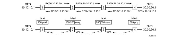
Figure 6 displays an example of an LSP path set up using RSVP. The ingress label edge router (ILER 1) transmits an RSVP path message (path: 30.30.30.1) downstream to the egress label edge router (ELER 4). The path message contains a label request object that requests intermediate LSRs and the ELER to provide a label binding for this path.
This gr-helper command enables the RSVP Graceful Restart Helper feature.
config
router
[no] mpls
[no] lsp lsp-name p2mp-lsp
[no] egress-statistics
accounting-policy policy-id
no accounting-policy
[no] collect-stats
[no] shutdown
config
router
[no] mpls
lsp-template template-name p2mp
no lsp-template template-name
[no] egress-statistics
accounting-policy policy-id
no accounting-policy
[no] collect-stats
Session Name: lsp-name::path-name, where lsp-name component is encoded as follows:
config
router
[no] mpls
ingress-statistics
[no] lsp lsp-name sender sender-address
accounting-policy policy-id
no accounting-policy
[no] collect-stats
[no] shutdown
[no] p2mp-template-lsp rsvp-session-name
SessionNameString sender sender-address
accounting-policy policy-id
no accounting-policy
[no] collect-stats
max-stats integer<1-8192|max, default max>
no max-stats
[no] shutdown
When the matching is performed on a context, the user must enter the RSVP session name string in the format “templateName-svcId” to include the LSP template name as well as the mVPN VPLS/B-VPLS service ID as configured at the ingress LER. In this case, one or more P2MP LSP instances signaled by the same ingress LER could be associated with the ingress statistics configuration. In this case, the user is provided with CLI parameter
max-stats to limit the maximum number of stat indices which can be assigned to this context. If the context matches more than this value, the additional request for stat indices from this context will be rejected.
Note: The rules when configuring an ingress statistics context based on template matching are the following:
|
1.
|
max-stats once allocated can be increased but not decreased unless the entire ingress statistics context matching a template name is deleted.
|
When the Point-of-Local Repair (PLR) node activates the bypass LSP by sending a PATH message to refresh the path state of protected LSP at the Merge-Point (MP) node, it must use an IPv4 tunnel sender address in the sender template object that is different than the one used by the ingress LER in the PATH message. These are the procedures specified in RFC 4090 and that are followed in the 7x50 implementation.
The 7x50 uses the address of the outgoing interface of the bypass LSP as the IPv4 tunnel sender address in the sender template object. This address will be different from the system interface address used in the sender template of the protected LSP by the ingress LER and thus there are no conflicts when the ingress LER acts as a PLR.
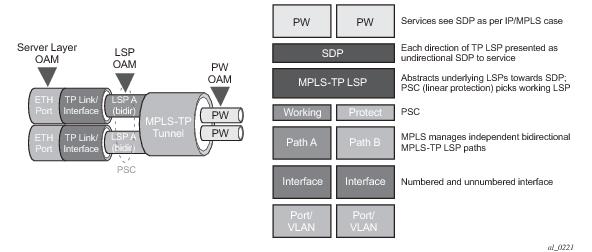
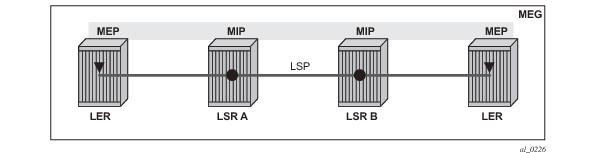
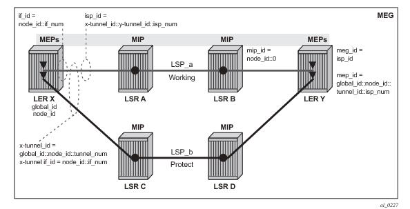
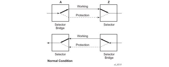
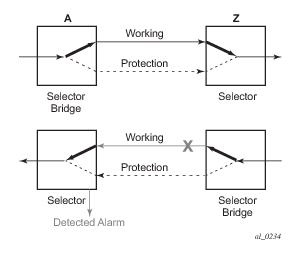
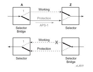
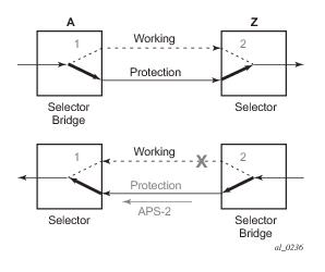
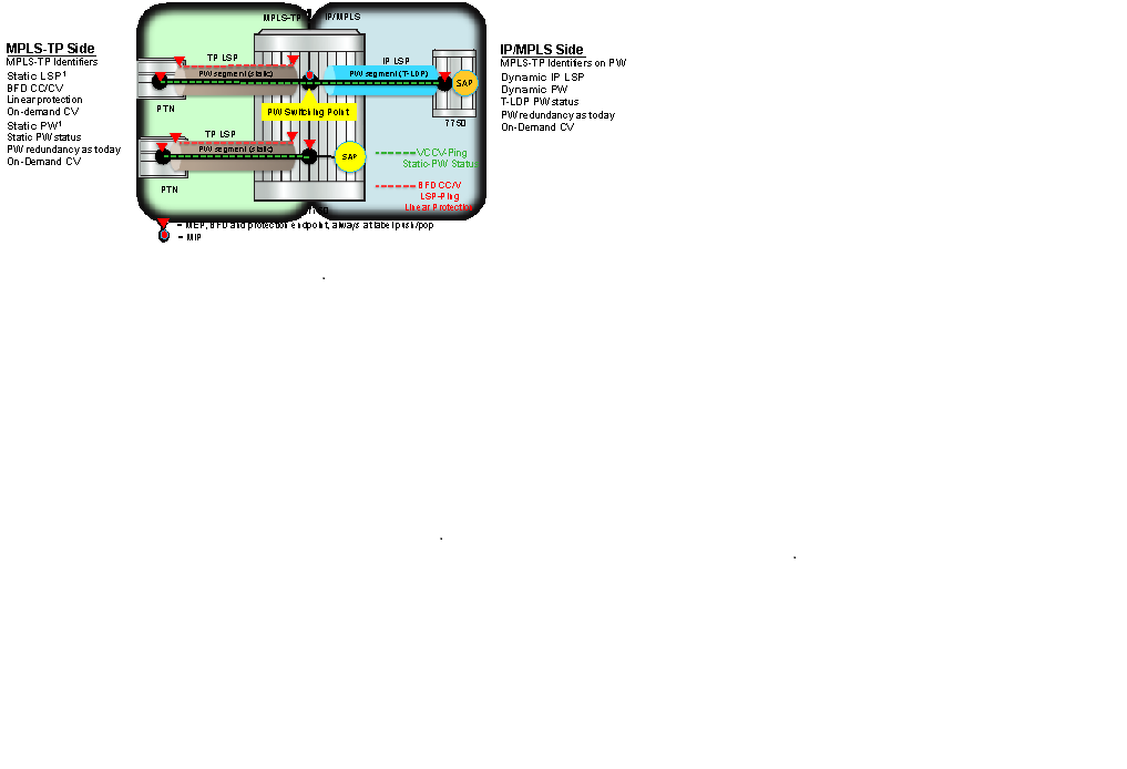
Figure 7 shows a high level functional model for MPLS-TP in SROS. LSP A and LSP B are the working and protect LSPs of an LSP tunnel. These are modeled as working and protect paths of an MPLS-TP LSP in SROS. MPLS-TP OAM runs in-band on each path. 1:1 linear protection coordinates the working and protect paths, using a protection switching coordination protocol (PSC) that runs in-band on each path over a Generic Associated Channel (G-ACh) on each path. Each path can use either an IP numbered, IP unnumbered, or MPLS-TP unnumbered (i.e. non-IP) interface.
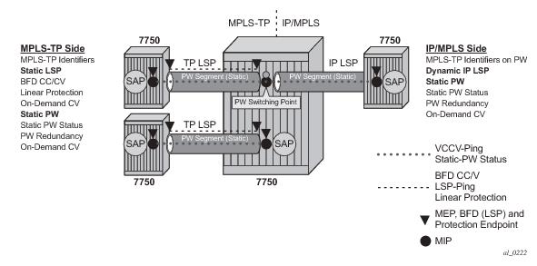
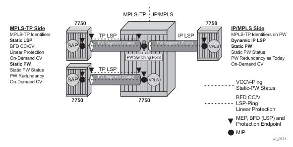
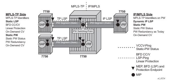
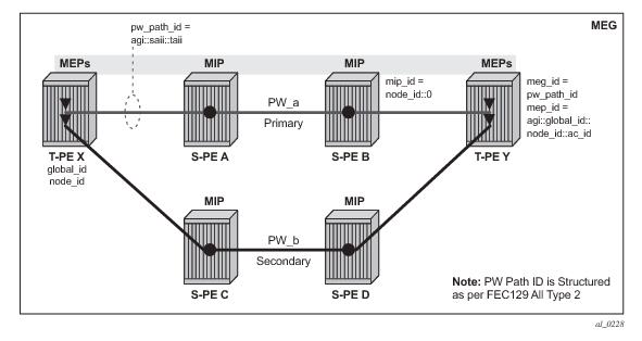
Figure 8 illustrates the use of the system as a T-PE for services in an MPLS-TP domain, and as a S-PE for services between
The MPLS-TP Tunnel ID and LSP ID are not to be confused with the RSVP-TE tunnel id implemented on the 7x50 system. Table 4 shows how these map to the X and Y ends of the tunnel shown in the above figure for the case of co-routed bidirectional LSPs.
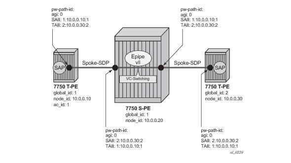
In the PW information model shown in Figure 14, the MS-PW is identified by the PW Path ID that is composed of the full AGI:SAII:TAII. The PW Path ID is also the MEP ID at the T-PEs, so a user does not have to explicitly configure a MEP ID; it is automatically derived by the system. For MPLS-TP PWs with static labels, although the PW is not signaled end-to-end, the directionality of the SAII and TAII is taken to be the same as for the equivalent label mapping message i.e. from downstream to upstream. This is to maintain consistency with signaled pseudowires using FEC 129.
Figure 15 shows an example of how the PW Path IDs can be configured for a simple two-segment MS-PW.
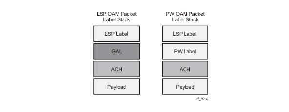
RFC5586 specifies mechanisms for implementing the G-ACh, relying on the combination of a reserved MPLS label, the 'Generic-ACH Label (GAL)', as an alert mechanism (value=13) and Generic Associated Channel Header (G-ACH) for MPLS LSPs, and using the Generic Associated Channel Header, only, for MPLS PWs (although the GAL is allowed on PWs). The purpose of the GAL is to indicate that a G-ACH resides at the bottom of the label stack, and is only visible when the bottom non-reserved label is popped. The G-ACH channel type is used to indicate the packet type carried on the G-ACh. Packets on a G-ACh are targeted to a node containing a MEP by ensuring that the GAL is pushed immediately below the label that is popped at the MEP (e.g. LSP endpoint or PW endpoint), so that it can be inspected as soon as the label is popped. A G-ACh packet is targeted to a node containing a MIP by setting the TTL of the LSP or PW label, as applicable, so that it expires at that node, in a similar manner to the SROS implementation of VCCV for MS-PWs.
In order to constrain the CPU resources consumed processing control channel status messages, the system implements a credit-based mechanism. If a user enables control channel status on a PW[n], then a certain number of credits c_n are consumed from a CPM-wide pool of max_credit credits. The number of credits consumed is inversely proportional to the configured refresh timer (the first three messages at 1 second interval do not count against the credit). If the current_credit <= 0, then control channel status signaling cannot be configured on a PW (but the PW can still be configured and no shutdown).
The system implements a hold-down timer for control-channel-status PW-status bits in order to suppress bouncing of the status of a PW. For a specific spoke-SDP, if the system receives 10 PW-status change events in 10 seconds, the system will
hold-down the spoke-SDP on the local node with the last received non-zero PW-status bits for 20 seconds. It will update the local spoke with the most recently received PW-status. This hold down timer is not persistent across shutdown/no-shutdown events.
The system implements an optional PW control channel status request mechanism. This enhances the existing control channel status mechanism so that a peer that has stale PW status for the far-end of a PW can request that the peer PE send a static PW status update. Accurate and current information about the far end status of a PW is important for proper operation of PW redundancy. This mechanism ensures a consistent view of the control plane is maintained, as far as possible, between peer nodes. It is not intended to act as a continuity check between peer nodes.
Generic MPLS-TP parameters are configured under config>router>mpls>mpls-tp. If a user configures
no mpls, normally the entire mpls configuration is deleted. However, in the case of mpls-tp a check that there is no other mpls-tp configuration e.g. services or tunnels using mpls-tp on the node, will be performed.
config
router
mpls
[no] mpls-tp
. . .
[no] shutdown
A shutdown of mpls-tp will therefore bring down all MPLS-TP LSPs on the system.
config
router
mpls
mpls-tp
global-id <global-id>
node-id {<ipv4address> | | <1.. .4,294,967,295>}
[no] shutdown
exit
In order to change the values, config>router>mpls>mpls-tp must be in the shutdown state. This will bring down all of the MPLS-TP LSPs on the node. New values are propagated to the system when a
no shutdown is performed.
config
router
mpls-labels
[no] static-label max-lsp-labels <number>
static-svc-label <number>
config
router
mpls
mpls-tp
[no] tp-tunnel-id-range <start-id> <end-id>
config
router
interface <if-name> [unnumbered-mpls-tp]
port <port-id>[:encap-val]
mac <local-mac-address>
static-arp <remote-mac-addr>
//ieee-address needs to support mcast and bcast
exit
The remote-mac-address may be any unicast, broadcast of multicast address. However, a broadcast or multicast remote-mac-address is only allowed in the
static-arp command on Ethernet unnumbered interfaces when the
unnumbered-mpls-tp keyword has been configured. This also allows the interface to accept packets on a broadcast or any multicast MAC address. Note that if a packet is received with a unicast destination MAC address, then it will be checked against the configured <local-mac-address> for the interface, and dropped if it does not match. When an interface is of type
unnumbered-mpls-tp, only MPLS-TP LSPs are allowed on that interface; other protocols are blocked from using the interface.
If required, the IF_Num is configured under a MEP context under the MPLS interface. The mpls-tp-mep context is created under the interface as shown below. The
if-num parameter, when concatenated with the Node ID, forms the IF_ID (as per RFC 6370), which is the identifier of this MEP. Note that it is possible to configure this context whether the interface is IP numbered, IP unnumbered or mpls-tp unnumbered:
config
router
mpls
interface <ip-int-name>
mpls-tp-mep
[no] if-num <if-num>
[no] if-num-validation [enable|disable]
...
exit
The if-num-validation command is used to enable or disable validation of the if-num in LSP Trace packet against the locally configured if-num for the interface over which the LSP Trace packet was received at the egress LER. This is because some implementations, do not perform interface validation for unnumbered MPLS-TP interfaces and instead set the if-num in the dsmap TLV to 0. The default is enabled.
MPLS-TP tunnels are configured using the mpls-tp LSP type at an LER under the LSP configuration, using the following CLI tree:
config
router
mpls
lsp <xyz> [bypass-only|p2mp-lsp|mpls-tp <src-tunnel-num>]
to node-id {<a.b.c.d> | <1.. .4,294,967,295>}
dest-global-id <global-id>
dest-tunnel-number <tunnel-num>
[no] working-tp-path
lsp-num <lsp-num>
in-label <in-label>
out-label <out-label> out-link <if-name>
[next-hop <ipv4-address>]
[no] mep
[no] oam-template <name>
[no] bfd-enable [cc | cc_cv] // defaults to cc
[no] shutdown
exit
[no] shutdown
exit
[no] protect-tp-path
lsp-num <lsp-num>
in-label <in-label>
out-label <out-label> out-link <if-name>
[next-hop <ipv4-address> ]
[no] mep
[no] protection-template <name>
[no] oam-template <name>
[no] bfd-enable [cc | cc_cv] //defaults to cc
[no] shutdown
exit
[no] shutdown
exit
<if-name> could be numbered or unnumbered interface using an Ethernet port.
<src-tunnel-num> is a mandatory create time parameter for mpls-tp tunnels, and has to be assigned by the user based on the configured range of tunnel ids. The
src-global-id used for the LSP ID is derived from the node-wide
global-id value configured under config>router>mpls>mpls-tp. A tunnel can not be
un shutdown unless the
global-id is configured.
The to node-id address may be entered in 4-octet IPv4 address format or unsigned 32-bit format. This is the far-end node-id for the LSP, and does do need to be routable IP addresses.
The from and
to addresses are used as the from and to node-id in the MPLS-TP Tunnel Identifier used for the MEP ID.
The to global-id is an optional parameter. If it is not entered, then the destination global ID takes the default value of 0. Global ID values of 0 are allowed and indicate that the node’s configured Global ID should be used. If the local global ID value is 0, then the remote
to global ID must also be 0. The
to global ID value cannot be changed if an LSP is in use by an SDP.
The to tunnel number is an optional parameter. If it is not entered, then it is taken to be the same value as the source tunnel number.
The next-hop ip-address can only be configured if the out-link if-name refers to a numbered IP interface. In this case, the system will determine the interface to use to reach the configured next-hop, but will check that the user-entered value for the out-link corresponds to the link returned by the system. If they do not correspond, then the path will not come up. Note that if a user changes the physical port referred to in the interface configuration, then BFD, if configured on the LSP, will go down. Users should therefore ensure that an LSP is moved to a different interface with a different port configuration in order to change the port that it uses. This is enforced by blocking the next-hop configuration for an unnumbered interface.
|
•
|
The lsp-num parameter is optional. The default values are 1 for the working-tp-path and 2 for protect-tp-path.
|
|
•
|
The mep context must be deleted before a path can be deleted.
|
|
•
|
An MPLS interface needs to be created under config>router>mpls>interface before using/specifying the out-label/out-link in the Forward path for an MPLS-TP LSP. Creation of the LSP will fail if the corresponding mpls interface doesn't exist even though the specified router interface may be valid.
|
|
•
|
If bfd-enable cc is configured, then CC-only mode using ACh channel 0x07 is used. If bfd-enable cc_v is configured, then BFD CC packets use channel 0x22 and CV packets use channel 0x23.
|
config
router
mpls
lsp
working-tp-path
mep
dsmap <in-if-num>[:<out-if-num>]
config
router
mpls
lsp
protect-tp-path
mep
dsmap <in-if-num>[:<out-if-num>]
config
router
mpls
mpls-tp
transit-path
forward-path
mip
dsmap <in-if-num>[:<out-if-num>]
exit
reverse-path
mip
dsmap <in-if-num>[:<out-if-num>]
exit
A node sending a DSMAP TLV will include these in-if-num and
out-if-num (if configured) values. Additionally, it will include the out-label for the LSP in the Label TLV for the DSMAP in the echo request message.
config
router
bfd
[no] bfd-template <name>
[no] transmit-interval <transmit-interval>
[no] receive-interval <receive-interval>
[no] echo-receive <echo-interval>
[no] multiplier <multiplier>
[no] type <cpm-np>
exit
|
•
|
transmit-interval transmit-interval and the rx receive-interval: These are the transmit and receive timers for BFD packets. If the template is used for MPLS-TP, then these are the timers used by CC packets. Values are in milliseconds: 10ms to 100,000ms, with 1ms granularity. Default 10ms for CPM3 or better, 1 sec for other hardware. Note that for MPLS-TP CV packets, a transmit interval of 1 sec is always used.
|
|
•
|
multiplier multiplier: Integer 3 – 20. Default: 3. This parameter is ignored for MPLS-TP combined cc-v BFD sessions, and the default of 3 used, as per RFC6428.
|
|
•
|
echo-receive echo-interval: Sets the minimum echo receive interval, in milliseconds, for a session. Values: 100ms – 100,000ms. Default: 100. This parameter is not used by a BFD session for MPLS-TP.
|
|
•
|
type cpm-np: This selects the CPM network processor as the local termination point for the BFD session. This is enabled by default.
|
Commands within the BFD-template use a begin-commit model. To edit any value within the BFD template, a begin needs to be executed once the template context has been entered. However, a value will still be stored temporarily until the commit is issued. Once the commit is issued, values will actually be used by other modules like the mpls-tp module and BFD module.
config
router
mpls
mpls-tp
[no] oam-template <name>
[no] bfd-template <name>
[no] hold-time-down <interval>
[no] hold-time-up <interval>
exit
|
•
|
hold-time-down interval: 0-5000 deciseconds, 10ms steps, default 0. This is equivalent to the standardized hold-off timer.
|
|
•
|
hold-time-up interval: 0-500 centiseconds in 100ms steps, default 2 seconds This is an additional timer that can be used to reduce BFD bouncing.
|
|
•
|
bfd-template name: This is the named BFD template to use for any BFD sessions enabled under a MEP for which the OAM template is configured.
|
config
router
mpls
mpls-tp
protection-template <name>
[no] revertive
[no] wait-to-restore <interval>
rapid-psc-timer <interval>
slow-psc-timer <interval>
exit
|
•
|
wait-to-restore interval: 0-720 seconds, 1 sec steps, default 300 seconds. This is applicable to revertive mode only.
|
|
•
|
revertive: Selects revertive behavior. Default: no revertive.
|
tools>perform>router>mpls
tp-tunnel
clear {<lsp-name> | id <tunnel-id>}
force {<lsp-name> | id <tunnel-id>}
lockout {<lsp-name> | id <tunnel-id>}
manual {<lsp-name> | id <tunnel-id>}
exit
exit
config
router
mpls
mpls-tp
transit-path <path-name>
[no] path-id {lsp-num <lsp-num>|working-path|protect-path
[src-global-id <global-id>]
src-node-id {<ipv4address> | <1.. .4,294,967,295>}
src-tunnel-num <tunnel-num>
[dest-global-id <global-id>]
dest-node-id {<ipv4address> | <1.. .4,294,967,295>}
[dest-tunnel-num <tunnel-num>]}
forward-path
in-label <in-label> out-label <out-label>
out-link <if-name> [next-hop <ipv4-next-hop>]
reverse-path
in-label <in-label> out-label <out-label>
[out-link <if-name> [next-hop <ipv4-next-hop>]
[no] shutdown
Note that the src-tunnel-num and
dest-tunnel-num are consistent with the source and destination of a label mapping message for a signaled LSP.
If dest-tunnel-num is not entered in CLI, the
dest-tunnel-num value is taken to be the same as the SRC-tunnel-num value.
If any of the global-id values are not entered, the value is taken to be 0.
If the src-global-id value is entered, but the
dest-global-id value is not entered,
dest-global-id value is the same as the
src-global-id value.
Note that the lsp-num must match the value configured in the LER for a given path. If no explicit lsp-num is configured, then working-path or protect-path must be specified (equating to 1 or 2 in the system).
*A:mlstp-dutA# show router mpls
mpls mpls-labels
*A:mlstp-dutA# show router mpls label
label label-range
*A:7950 XRS-20# show router mpls-labels label-range
=======================================================================
Label Ranges
=======================================================================
Label Type Start Label End Label Aging Available Total
-----------------------------------------------------------------------
Static 32 18431 - 18400 18400
Dynamic 18432 524287 0 505856 505856
Seg-Route 0 0 - 0 505856
=======================================================================
*A:mlstp-dutA# show router mpls tp-lsp
- tp-lsp [<lsp-name>] [status {up|down}] [from <ip-address>|to <ip-address>]
[detail]
- tp-lsp [<lsp-name>] path [protect|working] [detail]
- tp-lsp [<lsp-name>] protection
<lsp-name> : [32 chars max] - accepts * as wildcard char
<path> : keyword - Display LSP path information.
<protection> : keyword - Display LSP protection information.
<up|down> : keywords - Specify state of the LSP
<ip-address> : a.b.c.d
<detail> : keyword - Display detailed information.
*A:mlstp-dutA# show router mpls tp-lsp
path
protection
to <a.b.c.d>
<lsp-name>
"lsp-32" "lsp-33" "lsp-34" "lsp-35" "lsp-36" "lsp-37" "lsp-38" "lsp-39"
"lsp-40" "lsp-41"
status {up|down}
from <ip-address>
detail
*A:mlstp-dutA# show router mpls tp-lsp "lsp-
"lsp-32" "lsp-33" "lsp-34" "lsp-35" "lsp-36" "lsp-37" "lsp-38" "lsp-39"
"lsp-40" "lsp-41"
*A:mlstp-dutA# show router mpls tp-lsp "lsp-32"
===============================================================================
MPLS MPLS-TP LSPs (Originating)
===============================================================================
LSP Name To Tun Protect Adm Opr
Id Path
-------------------------------------------------------------------------------
lsp-32 0.0.3.234 32 No Up Up
-------------------------------------------------------------------------------
LSPs : 1
===============================================================================
*A:mlstp-dutA# show router mpls tp-lsp "lsp-32" detail
===============================================================================
MPLS MPLS-TP LSPs (Originating) (Detail)
===============================================================================
-------------------------------------------------------------------------------
Type : Originating
-------------------------------------------------------------------------------
LSP Name : lsp-32
LSP Type : MplsTp LSP Tunnel ID : 32
From Node Id: 0.0.3.233+ To Node Id : 0.0.3.234
Adm State : Up Oper State : Up
LSP Up Time : 0d 04:50:47 LSP Down Time : 0d 00:00:00
Transitions : 1 Path Changes : 2
===============================================================================
*A:mlstp-dutA# show router mpls tp-lsp path
===============================================================================
MPLS-TP LSP Path Information
===============================================================================
LSP Name : lsp-32 To : 0.0.3.234
Admin State : Up Oper State : Up
-------------------------------------------------------------------------------
Path NextHop InLabel OutLabel Out I/F Admin Oper
-------------------------------------------------------------------------------
Working 32 32 AtoB_1 Up Down
Protect 2080 2080 AtoC_1 Up Up
===============================================================================
LSP Name : lsp-33 To : 0.0.3.234
Admin State : Up Oper State : Up
-------------------------------------------------------------------------------
Path NextHop InLabel OutLabel Out I/F Admin Oper
-------------------------------------------------------------------------------
Working 33 33 AtoB_1 Up Down
Protect 2082 2082 AtoC_1 Up Up
===============================================================================
LSP Name : lsp-34 To : 0.0.3.234
Admin State : Up Oper State : Up
-------------------------------------------------------------------------------
Path NextHop InLabel OutLabel Out I/F Admin Oper
-------------------------------------------------------------------------------
Working 34 34 AtoB_1 Up Down
Protect 2084 2084 AtoC_1 Up Up
===============================================================================
LSP Name : lsp-35 To : 0.0.3.234
Admin State : Up Oper State : Up
-------------------------------------------------------------------------------
Path NextHop InLabel OutLabel Out I/F Admin Oper
-------------------------------------------------------------------------------
Working 35 35 AtoB_1 Up Down
Protect 2086 2086 AtoC_1 Up Up
===============================================================================
LSP Name : lsp-36 To : 0.0.3.234
Admin State : Up Oper State : Up
-------------------------------------------------------------------------------
Path NextHop InLabel OutLabel Out I/F Admin Oper
-------------------------------------------------------------------------------
Working 36 36 AtoB_1 Up Down
Protect 2088 2088 AtoC_1 Up Up
===============================================================================
LSP Name : lsp-37 To : 0.0.3.234
Admin State : Up Oper State : Up
-------------------------------------------------------------------------------
Path NextHop InLabel OutLabel Out I/F Admin Oper
-------------------------------------------------------------------------------
Working 37 37 AtoB_1 Up Down
Protect 2090 2090 AtoC_1 Up Up
===============================================================================
LSP Name : lsp-38 To : 0.0.3.234
Admin State : Up Oper State : Up
-------------------------------------------------------------------------------
Path NextHop InLabel OutLabel Out I/F Admin Oper
-------------------------------------------------------------------------------
Working 38 38 AtoB_1 Up Down
Protect 2092 2092 AtoC_1 Up Up
===============================================================================
LSP Name : lsp-39 To : 0.0.3.234
Admin State : Up Oper State : Up
-------------------------------------------------------------------------------
Path NextHop InLabel OutLabel Out I/F Admin Oper
-------------------------------------------------------------------------------
Working 39 39 AtoB_1 Up Down
Protect 2094 2094 AtoC_1 Up Up
===============================================================================
LSP Name : lsp-40 To : 0.0.3.234
Admin State : Up Oper State : Up
-------------------------------------------------------------------------------
Path NextHop InLabel OutLabel Out I/F Admin Oper
-------------------------------------------------------------------------------
Working 40 40 AtoB_1 Up Down
Protect 2096 2096 AtoC_1 Up Up
===============================================================================
LSP Name : lsp-41 To : 0.0.3.234
Admin State : Up Oper State : Up
-------------------------------------------------------------------------------
Path NextHop InLabel OutLabel Out I/F Admin Oper
-------------------------------------------------------------------------------
Working 41 41 AtoB_1 Up Down
Protect 2098 2098 AtoC_1 Up Up
*A:mlstp-dutA# show router mpls tp-lsp "lsp-32" path working
===============================================================================
MPLS-TP LSP Working Path Information
LSP: "lsp-32"
===============================================================================
LSP Name : lsp-32 To : 0.0.3.234
Admin State : Up Oper State : Up
-------------------------------------------------------------------------------
Path NextHop InLabel OutLabel Out I/F Admin Oper
-------------------------------------------------------------------------------
Working 32 32 AtoB_1 Up Down
===============================================================================
*A:mlstp-dutA# show router mpls tp-lsp "lsp-32" path protect
===============================================================================
MPLS-TP LSP Protect Path Information
LSP: "lsp-32"
===============================================================================
LSP Name : lsp-32 To : 0.0.3.234
Admin State : Up Oper State : Up
-------------------------------------------------------------------------------
Path NextHop InLabel OutLabel Out I/F Admin Oper
-------------------------------------------------------------------------------
Protect 2080 2080 AtoC_1 Up Up
===============================================================================
*A:mlstp-dutA# show router mpls tp-lsp "lsp-32" path protect detail
===============================================================================
MPLS-TP LSP Protect Path Information
LSP: "lsp-32" (Detail)
===============================================================================
LSP Name : lsp-32 To : 0.0.3.234
Admin State : Up Oper State : Up
Protect path information
-------------------------------------------------------------------------------
Path Type : Protect LSP Num : 2
Path Admin : Up Path Oper : Up
Out Interface : AtoC_1 Next Hop Addr : n/a
In Label : 2080 Out Label : 2080
Path Up Time : 0d 04:52:17 Path Dn Time : 0d 00:00:00
Active Path : Yes Active Time : 0d 00:52:56
MEP information
MEP State : Up BFD : cc
OAM Templ : privatebed-oam-template CC Status : inService
CV Status : unknown
Protect Templ : privatebed-protection-template WTR Count Down: 0 seconds
RX PDU : SF (1,1) TX PDU : SF (1,1)
Defects :
===============================================================================
*A:mlstp-dutA# show router mpls tp-lsp "lsp-32" path working detail
===============================================================================
MPLS-TP LSP Working Path Information
LSP: "lsp-32" (Detail)
===============================================================================
LSP Name : lsp-32 To : 0.0.3.234
Admin State : Up Oper State : Up
Working path information
-------------------------------------------------------------------------------
Path Type : Working LSP Num : 1
Path Admin : Up Path Oper : Down
Down Reason : ccFault ifDn
Out Interface : AtoB_1 Next Hop Addr : n/a
In Label : 32 Out Label : 32
Path Up Time : 0d 00:00:00 Path Dn Time : 0d 00:53:01
Active Path : No Active Time : n/a
MEP information
MEP State : Up BFD : cc
OAM Templ : privatebed-oam-template CC Status : outOfService
CV Status : unknown
===============================================================================
*A:mlstp-dutA#
*A:mlstp-dutA# show router mpls tp-lsp protection
===============================================================================
MPLS-TP LSP Protection Information
Legend: W-Working, P-Protect,
===============================================================================
LSP Name Admin Oper Path Ingr/Egr Act. Rx PDU
State State State Label Path Tx PDU
-------------------------------------------------------------------------------
lsp-32 Up Up W Down 32/32 No SF (1,1)
P Up 2080/2080 Yes SF (1,1)
lsp-33 Up Up W Down 33/33 No SF (1,1)
P Up 2082/2082 Yes SF (1,1)
lsp-34 Up Up W Down 34/34 No SF (1,1)
P Up 2084/2084 Yes SF (1,1)
lsp-35 Up Up W Down 35/35 No SF (1,1)
P Up 2086/2086 Yes SF (1,1)
lsp-36 Up Up W Down 36/36 No SF (1,1)
P Up 2088/2088 Yes SF (1,1)
lsp-37 Up Up W Down 37/37 No SF (1,1)
P Up 2090/2090 Yes SF (1,1)
lsp-38 Up Up W Down 38/38 No SF (1,1)
P Up 2092/2092 Yes SF (1,1)
lsp-39 Up Up W Down 39/39 No SF (1,1)
P Up 2094/2094 Yes SF (1,1)
lsp-40 Up Up W Down 40/40 No SF (1,1)
P Up 2096/2096 Yes SF (1,1)
lsp-41 Up Up W Down 41/41 No SF (1,1)
P Up 2098/2098 Yes SF (1,1)
-------------------------------------------------------------------------------
No. of MPLS-TP LSPs: 10
===============================================================================
*A:mlstp-dutA# show router mpls mpls-tp
- mpls-tp
oam-template - Display MPLS-TP OAM Template information
protection-tem* - Display MPLS-TP Protection Template information
status - Display MPLS-TP system configuration
transit-path - Display MPLS-TP Tunnel information
*A:mlstp-dutA# show router mpls mpls-tp oam-template
===============================================================================
MPLS-TP OAM Templates
===============================================================================
Template Name : privatebed-oam-template Router ID : 1
BFD Template : privatebed-bfd-template Hold-Down Time: 0 centiseconds
Hold-Up Time : 20 deciseconds
===============================================================================
*A:mlstp-dutA# show router mpls mpls-tp protection-template
===============================================================================
MPLS-TP Protection Templates
===============================================================================
Template Name : privatebed-protection-template Router ID : 1
Protection Mode: one2one Direction : bidirectional
Revertive : revertive Wait-to-Restore: 300sec
Rapid-PSC-Timer: 10ms Slow-PSC-Timer : 5sec
===============================================================================
*A:mlstp-dutA# show router mpls mpls-tp status
===============================================================================
MPLS-TP Status
===============================================================================
Admin Status : Up
Global ID : 42 Node ID : 0.0.3.233
Tunnel Id Min : 1 Tunnel Id Max : 4096
===============================================================================
*A:mlstp-dutA# show router mpls mpls-tp transit-path
- transit-path [<path-name>] [detail]
<path-name> : [32 chars max]
<detail> : keyword - Display detailed information.
A:mplstp-dutC# show router mpls mpls-tp transit-path
- transit-path [<path-name>] [detail]
<path-name> : [32 chars max]
<detail> : keyword - Display detailed information.
A:mplstp-dutC# show router mpls mpls-tp transit-path
<path-name>
"tp-32" "tp-33" "tp-34" "tp-35" "tp-36" "tp-37" "tp-38" "tp-39"
"tp-40" "tp-41"
detail
A:mplstp-dutC# show router mpls mpls-tp transit-path "tp-32"
===============================================================================
MPLS-TP Transit tp-32 Path Information
===============================================================================
Path Name : tp-32
Admin State : Up Oper State : Up
------------------------------------------------------------------
Path NextHop InLabel OutLabel Out I/F
------------------------------------------------------------------
FP 2080 2081 CtoB_1
RP 2081 2080 CtoA_1
===============================================================================
A:mplstp-dutC# show router mpls mpls-tp transit-path "tp-32" detail
===============================================================================
MPLS-TP Transit tp-32 Path Information (Detail)
===============================================================================
Path Name : tp-32
Admin State : Up Oper State : Up
-------------------------------------------------------------------------------
Path ID configuration
Src Global ID : 42 Dst Global ID : 42
Src Node ID : 0.0.3.234 Dst Node ID : 0.0.3.233
LSP Number : 2 Dst Tunnel Num: 32
Forward Path configuration
In Label : 2080 Out Label : 2081
Out Interface : CtoB_1 Next Hop Addr : n/a
Reverse Path configuration
In Label : 2081 Out Label : 2080
Out Interface : CtoA_1 Next Hop Addr : n/a
===============================================================================
A:mplstp-dutC#
*A:mlstp-dutA# show router interface "AtoB_1"
===============================================================================
Interface Table (Router: Base)
===============================================================================
Interface-Name Adm Opr(v4/v6) Mode Port/SapId
IP-Address PfxState
-------------------------------------------------------------------------------
AtoB_1 Down Down/-- Network 1/2/3:1
Unnumbered If[system] n/a
-------------------------------------------------------------------------------
Interfaces : 1
A:mlstp-dutA# tools dump router mpls tp-tunnel
- tp-tunnel <lsp-name> [clear]
- tp-tunnel id <tunnel-id> [clear]
<lsp-name> : [32 chars max]
<tunnel-id> : [1..61440]
<clear> : keyword - clear stats after reading
*A:mlstp-dutA# tools dump router mpls tp-tunnel "lsp-
"lsp-32" "lsp-33" "lsp-34" "lsp-35" "lsp-36" "lsp-37" "lsp-38" "lsp-39"
"lsp-40" "lsp-41"
*A:mlstp-dutA# tools dump router mpls tp-tunnel "lsp-32"
Idx: 1-32 (Up/Up): pgId 4, paths 2, operChg 1, Active: Protect
TunnelId: 42::0.0.3.233::32-42::0.0.3.234::32
PgState: Dn, Cnt/Tm: Dn 1/000 04:00:48.160 Up:3/000 00:01:25.840
MplsMsg: tpDn 0/000 00:00:00.000, tunDn 0/000 00:00:00.000
wpDn 0/000 00:00:00.000, ppDn 0/000 00:00:00.000
wpDel 0/000 00:00:00.000, ppDel 0/000 00:00:00.000
tunUp 1/000 00:00:02.070
Paths:
Work (Up/Dn): Lsp 1, Lbl 32/32, If 2/128 (1/2/3 : 0.0.0.0)
Tmpl: ptc: , oam: privatebed-oam-template (bfd: privatebed-bfd-template(np)-10 ms)
Bfd: Mode CC state Dn/Up handle 160005/0
Bfd-CC (Cnt/Tm): Dn 1/000 04:00:48.160 Up:1/000 00:01:23.970
State: Admin Up (1::1::1) port Up , if Dn , operChg 2
DnReasons: ccFault ifDn
Protect (Up/Up): Lsp 2, Lbl 2080/2080, If 3/127 (5/1/1 : 0.0.0.0)
Tmpl: ptc: privatebed-protection-template, oam: privatebed-oam-template (bfd: privatebed-bfd-template(np)-10 ms)
Bfd: Mode CC state Up/Up handle 160006/0
Bfd-CC (Cnt/Tm): Dn 0/000 00:00:00.000 Up:1/000 00:01:25.410
State: Admin Up (1::1::1) port Up , if Up , operChg 1
Aps: Rx - 5, raw 3616, nok 0(), txRaw - 3636, revert Y
Pdu: Rx - 0x1a-21::0101 (SF), Tx - 0x1a-21::0101 (SF)
State: PF:W:L LastEvt pdu (L-SFw/R-SFw)
Tmrs: slow
Defects: None Now: 000 05:02:19.130
Seq Event state TxPdu RxPdu Dir Act Time
=== ====== ======== ========== ========== ===== ==== ================
000 start UA:P:L SF (0,0) NR (0,0) Tx--> Work 000 00:00:02.080
001 pdu UA:P:L SF (0,0) SF (0,0) Rx<-- Work 000 00:01:24.860
002 pdu UA:P:L SF (0,0) NR (0,0) Rx<-- Work 000 00:01:26.860
003 pUp NR NR (0,0) NR (0,0) Tx--> Work 000 00:01:27.440
004 pdu NR NR (0,0) NR (0,0) Rx<-- Work 000 00:01:28.760
005 wDn PF:W:L SF (1,1) NR (0,0) Tx--> Prot 000 04:00:48.160
006 pdu PF:W:L SF (1,1) NR (0,1) Rx<-- Prot 000 04:00:48.160
007 pdu PF:W:L SF (1,1) SF (1,1) Rx<-- Prot 000 04:00:51.080
*A:bksim1611# /debug service id 700 sdp 200:700 event-type
{config-change|oper-status-change|neighbor-discovery|control-channel-status}
*A:bksim1611# /debug service id 700 sdp 200:700 event-type control-channel-status
*A:bksim1611#
1 2012/08/31 09:56:12.09 EST MINOR: DEBUG #2001 Base PW STATUS SIG PKT (RX):
"PW STATUS SIG PKT (RX)::
Sdp Bind 200:700 Instance 3
Version : 0x0
PW OAM Msg Type : 0x27
Refresh Time : 0xa
Total TLV Length : 0x8
Flags : 0x0
TLV Type : 0x96a
TLV Len : 0x4
PW Status Bits : 0x0
"
2 2012/08/31 09:56:22.09 EST MINOR: DEBUG #2001 Base PW STATUS SIG PKT (RX):
"PW STATUS SIG PKT (RX)::
Sdp Bind 200:700 Instance 3
Version : 0x0
PW OAM Msg Type : 0x27
Refresh Time : 0xa
Total TLV Length : 0x8
Flags : 0x0
TLV Type : 0x96a
TLV Len : 0x4
PW Status Bits : 0x0
"
3 2012/08/31 09:56:29.44 EST MINOR: DEBUG #2001 Base PW STATUS SIG PKT (TX):
"PW STATUS SIG PKT (TX)::
Sdp Bind 200:700 Instance 3
Version : 0x0
PW OAM Msg Type : 0x27
Refresh Time : 0x1e
Total TLV Length : 0x8
Flags : 0x0
TLV Type : 0x96a
TLV Len : 0x4
PW Status Bits : 0x0
Another decision made is local CAC and is performed when the RESV message for the LSP path is received in the reverse direction by a SR OS node in that path. The bandwidth value selected by the egress LER will be checked against link bandwidth, otherwise the reservation is rejected. If accepted, the new value for the remaining link bandwidth will be advertised by IGP at the next advertisement event.
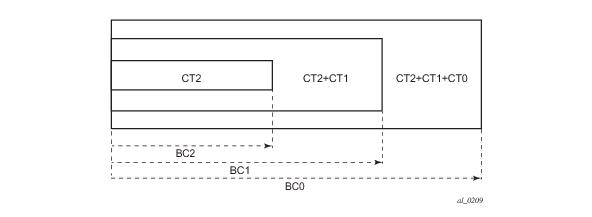
where the SUM is across all values of c in the range
b <= c <= (MaxCT - 1), and
BCb is the bandwidth constraint of
CTb.
where the SUM is across all values of
c in the range
0 <= c <= (MaxCT - 1)
An LSP of class-type CTc, setup priority
p, holding priority
h (h=<p), and bandwidth
B is admitted into a link if the following condition is satisfied:
where TE-Class [i] maps to <
CTc, p > in the definition of the TE classes on the node. The bandwidth reservation is effected at the holding priority, i.e., in
TE-class [j] = <CTc, h>. Thus, the reserved bandwidth for CTc and the unreserved bandwidth for the TE classes using CTc are updated as follows:
|
1.
|
The operator enables Diff-Serv TE by executing the diffserv-te command in the config>router>rsvp context. When this command is enabled, IS-IS and OSPF will start advertising available bandwidth for each TE class configured under the diffserv-te node. The operator can disable Diff-Serv TE globally by using the no form of the command.
|
|
6.
|
The diffserv-te command will only have effect if the operator has already enabled traffic engineering at the IS-IS and/or OSPF routing protocol levels:
|
a. Definition of TE classes, TE Class = {Class Type (CT), LSP priority}. Eight TE classes can be supported. There is no default TE class once Diff-Serv is enabled. The operator must explicitly define each TE class. However, when Diff-Serv is disabled there will be an internal use of the default CT (CT0) and eight preemption priorities as shown in
Table 6.
b. A mapping of the system forwarding class to CT. The default settings are shown in
Table 7.
c. Configuration of the percentage of RSVP interface bandwidth each CT shares, for example, the Bandwidth Constraint (BC), using the
class-type-bw command. The absolute value of the CT share of the interface bandwidth is derived as the percentage of the bandwidth advertised by IGP in the maximum reservable link bandwidth TE parameter, for example, the link bandwidth multiplied by the RSVP interface
subscription percentage parameter. Note that this configuration also exists at the RSVP interface level and the interface specific configured value overrides the global configured value. The BC value can be changed at any time. The operator can specify the BC for a CT which is not used in any of the TE class definition but that does not get used by any LSP originating or transiting this node.
d. Configuration of the Admission Control Policy to be used: only the Maximum Allocation Model (MAM) is supported. The MAM value represents the bandwidth constraint models for the admission control of an LSP reservation to a link.
The use of backup Class Type (CT) by an LSP is enabled by executing the config>router>mpls>lsp>primary>backup-class-type ct-number command at the LSP primary path level.
|
•
|
When the clear>router>mpls>lsp command is executed, the retry behavior for this LSP is the same as in the case of an unmapped LSP.
|
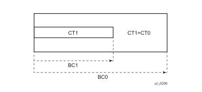
This feature introduces the Russian-Doll Model (RDM) Diff-Serv TE admission control policy described in RFC 4127, Russian Dolls Bandwidth Constraints Model for Diffserv-aware MPLS Traffic Engineering. This mode is enabled using the following command:
config>router>rsvp>diffserv-te rdm.
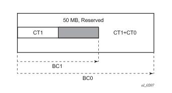
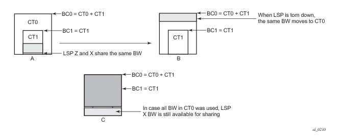
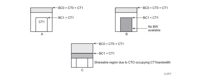
In Figure 29 (a), if the path X occupies the bandwidth as shown it can not share the bandwidth with the new path Z being setup. If a condition exists, as shown in
Figure 29, (b) the path Z can never be setup on this particular link.
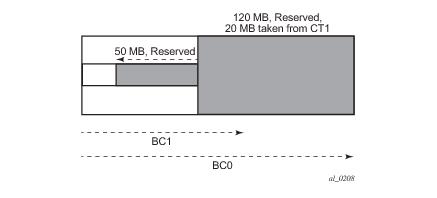
Consider Figure 29 (c). The CT0 has a region that overlaps with CT1 as CT0 has incursion into CT1. This overlap can be shared. However, in order to find whether such an incursion has occurred and how large the region is, it is required to know the reserved bandwidths in each class. Currently, IGP-TE advertises only the unreserved bandwidths. Hence, it is not possible to compute these overlap regions at the head end during CSPF. Moreover, the head end needs to then try and mimic each of the traversed links exactly which increases the complexity.
The tools perform router mpls update-path {
lsp lsp-name path current-path-name new-path new-path-name} command instructs MPLS to replace the path of the primary or secondary LSP.
The new path must be first configured in CLI or provided via SNMP. The configure router mpls path path-name CLI command is used to enter the path.
tools perform router mpls force-switch-path lsp lsp-name path path-name
tools perform router mpls no force-switch-path lsp lsp-name
If the one-hop option is specified instead of a prefix policy, this command enables the automatic signaling of one-hop point-to-point LSPs using the specified template to all directly connected neighbors. This LSP type is referred to as auto-LSP of type one-hop. Although the provisioning model and CLI syntax differ from that of a mesh LSP only by the absence of a prefix list, the actual behavior is quite different. When the above command is executed, the TE database will keep track of each TE link that comes up to a directly connected IGP neighbor whose router-id is discovered. It then instructs MPLS to signal an LSP with a destination address matching the router-id of the neighbor and with a strict hop consisting of the address of the interface used by the TE link. Thus, the
auto-lsp command with the
one-hop option will result in one or more LSPs signaled to the neighboring router.
An auto-created mesh or one-hop LSP can have egress statistics collected at the ingress LER by adding the egress-statistics node configuration into the LSP template. The user can also have ingress statistics collected at the egress LER using the same
ingress-statistics node in CLI used with a provisioned LSP. The user must specify the full LSP name as signaled by the ingress LER in the RSVP session name field of the Session Attribute object in the received Path message.
When rsvp-shortcut is enabled at the IGP instance level, all RSVP LSPs originating on this node are eligible by default as long as the destination address of the LSP, as configured in config-ure>router>mpls>lsp>to, corresponds to a router-id of a remote node. RSVP LSPs with a destination corresponding to an interface address or any other loopback interface address of a remote node are automatically not considered by IS-IS or OSPF. The user can, however, exclude a specific RSVP LSP from being used as a shortcut for resolving IGP routes by entering the command:
Table 8 summarizes the outcome in terms of RSVP LSP role of mixing these configuration options.
The no form of this command disables the resolution of IGP routes using RSVP shortcuts.
The relative-metric option is mutually exclusive with the
lfa-protect or the
lfa-only options. In other words, an LSP with the
relative-metric option enabled cannot be included in the LFA SPF and vice-versa when the
rsvp-shortcut option is enabled in the IGP.
Finally, it should be noted that the relative-metric option is ignored when forwarding adjacency is enabled in IS-IS or OSPF by configuring the
advertise-tunnel-link option. In this case, IGP advertises the LSP as a point-to-point unnumbered link along with the LSP operational metric capped to the maximum link metric allowed in that IGP.
If both rsvp-shortcut and
advertise-tunnel-link options are enabled for a given IGP instance, then the
advertise-tunnel-link will win. With this feature, ISIS or OSPF advertises an RSVP LSP as a link so that other routers in the network can include it in their SPF computations. The RSVP LSP is advertised as an unnumbered point-to-point link and the link LSP/LSA has no Traffic Engineering opaque sub-TLVs as per RFC 3906
Calculating Interior Gateway Protocol (IGP) Routes Over Traffic Engineering Tunnels.
Note that the igp-shortcut option under the LSP name governs the use of the LSP with both the
rsvp-shortcut and the
advertise-tunnel-link options in IGP. The interactions of these options are summarized in
Table 9:
Finally, note that the concurrent enabling of the advertise-tunnel-link option and the
multicast-import option will result a multicast RTM that is a copy of the unicast RTM and is thus populated with mix of IP and tunnel NHs. RPF will succeed for a prefix resolved to a IP NH, but will fail for a prefix resolved to a tunnel NH.
Table 10 summarizes the interaction of the
rsvp-shortcut and
advertise-tunnel-link options with unicast and multicast RTMs.
When the no form of the above command is enabled for local packets, TTL propagation is disabled on all locally generated IP packets, including ICMP Ping, trace route, and OAM packets that are destined to a route that is resolved to the LSP shortcut. In this case, a TTL of 255 is programmed onto the pushed label stack. This is referred to as pipe mode.
Similarly, when the no form is enabled for transit packets, TTL propagation is disabled on all IP packets received on any IES interface and destined to a route that is resolved to the LSP shortcut. In this case, a TTL of 255 is programmed onto the pushed label stack.
|
→
|
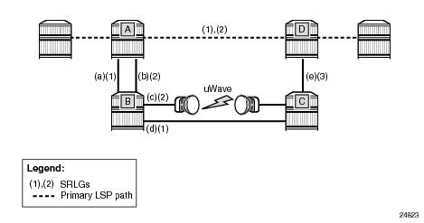
Enable the srlg-frr (strict/non-strict) option, which is a system-wide parameter, and it force every LSP path CSPF calculation, to take the configured SRLG membership(s) (and propagated through the IGP opaque-te-database) into account.
|
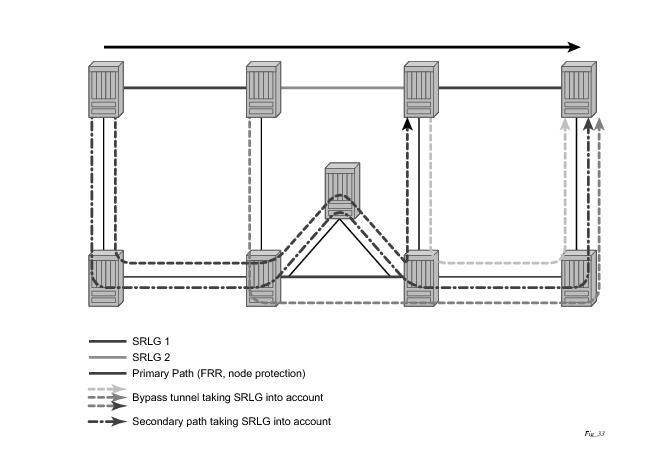
Figure 31 illustrates the operation of SRLG penalty weights.
A user can define a penalty weight value associate with an SRLG group using the penalty-weight parameter of the
srlg-group command under the
configure>
router-if-attribute context. If an SRLG penalty weight is configured, then CSPF will include the SRLG penalty weight in the computation of an FRR detour or bypass for protecting the primary LSP path at a PLR node. Links with a higher SRLG penalty should be more likely to be pruned than links with a lower SRLG penalty.
The user enters the SRLG membership information for any link in the network by using the interface ip-int-name srlg-group group-name command in the
config>router>mpls> srlg-database>router-id context. An interface can be associated with up to 5 SRLG groups for each execution of this command. The user can associate an interface with up to 64 SRLG groups by executing the command multiple times. The user must also use this command to enter the local interface SRLG membership into the user SRLG database. The user deletes a specific interface entry in this database by executing the
no form of this command.
The group-name must have been previously defined in the
srlg-group group-name value group-value command in the
config>router>mpls if-attribute. The maximum number of distinct SRLG groups the user can configure on the system is 1024.
The parameter value for router-id must correspond to the router ID configured under the base router instance, the base OSPF instance or the base IS-IS instance of a given node. Note however that a single user SLRG database is maintained per node regardless if the listed interfaces participate in static routing, OSPF, IS-IS, or both routing protocols. The user can temporarily disable the use by CSPF of all interface membership information of a specific router ID by executing the
shutdown command in the
config>router>mpls> srlg-database> router-id context. In this case, CSPF will assume these interfaces have no SRLG membership association. The operator can delete all interface entries of a specific router ID entry in this database by executing the
no router-id router-address command in the
config>router>mpls> srlg-database context.
The operator enables the use by CSPF of the user SRLG database by entering the user-srlg-db enable command in the config>router>mpls context. When the MPLS module makes a request to CSPF for the computation of an SRLG secondary path, CSPF will query the local SRLG and computes a path after pruning links which are members of the SRLG IDs of the associated primary path. Similarly, when MPLS makes a request to CSPF for a FRR bypass or detour path to associate with the primary path, CSPF queries the user SRLG database and computes a path after pruning links which are members of the SRLG IDs of the PLR outgoing interface.
The operator can disable the use of the user SRLG database by entering the user-srlg-db disable in command in the config>router>mpls context. CSPF will then resumes queries into the TE database for SRLG membership information. However, the user SRLG database is maintained
The operator can delete the entire SRLG database by entering the no srlg-database command in the
config>router>mpls context. In this case, CSPF will assume all interfaces have no SRLG membership association if the user has not disabled the use of this database.
Graceful shutdown provides a method to bulk re-route transit LSPs away from the node during software upgrade of a node. A solution is described in RFC 5817, Graceful Shutdown in MPLS and Generalized MPLS Traffic Engineering Networks. This is achieved in this RFC by using a PathErr message with a specific error code Local Maintenance on TE link required flag. When a LER gets this message, it performs a make-before-break on the LSP path to move the LSP away from the links/nodes which IP addresses were indicated in the PathErr message.
|
•
|
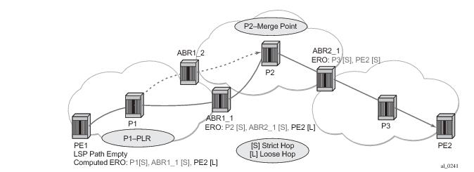
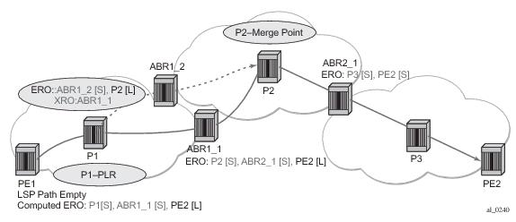
The use-te-metric option in CSPF cannot be propagated across the area boundary and thus will operate within the scope of the local area of the ingress LER node. This is a new behavior introduced with the automatic ABR selection feature.
|
|
•
|
The srlg option on bypass LSP will continue to operate locally at each PLR within each area. The PLR node protecting the ABR will check the SRLG constraint for the path of the bypass within the local area.
|
|
•
|
The srlg option on secondary path is allowed to operate within the scope of the local area of the ingress LER node with the automatic ABR selection feature.
|
|
•
|
The least-fill option support with an inter-area LSP is introduced with the automatic ABR selection feature. When this option is enabled, CSPF applies the least-fill criterion to select the path segment to the exit ABR node in the local area.
|
|
•
|
The propagate-admin-group option under the LSP will still need to be enabled on the inter-area LSP if the user wants to have admin-groups propagated across the areas.
|
config>router>mpls>auto-lsp lsp-template template-name policy peer-prefix-policy
The user must perform a no shutdown of the template before it takes effect. Once a template is in use, the user must shutdown the template before effecting any changes to the parameters except for those LSP parameters for which the change can be handled with the Make-Before-Break (MBB) procedures. These parameters are
bandwidth and enabling
fast-reroute with or without the
hop-limit or
node-protect options. For all other parameters, the user shuts down the template and once a it is added, removed or modified, the existing instances of the LSP using this template are torn down and re-signaled.
If the user changes the bandwidth parameter in the LSP template, an MBB is performed for all LSPs using the template. If however the
auto-bandwidth option was enabled in the template, the bandwidth
parameter change will be saved but will only take effect at the next time the LSP bounces or is re-signaled.
Note that the use of the ‘tools perform router mpls update-path’ command with a mesh LSP is not supported.
The one-to-one option under
fast-reroute is also not supported.
Where DestIpv4Address is the address of the destination of the auto-created LSP.
config
router
[no] mpls
lsp-template template-name mesh-p2p]
no lsp-template template-name
[no] egress-statistics
accounting-policy policy-id
no accounting-policy
[no] collect-stats
config
router
[no] mpls
lsp
[no] revert-timer <timer-value>
When configured, the revert timer is started as soon as a primary path recovers. The LSP does not revert from the currently used secondary path to the primary path until the timer expires. When configured, the revert-timer is used instead of the existing hold timer.
The no form of the command cancels any currently outstanding revert timer and causes the LSP to revert to the primary path if it is up.
The LSP and path parameters and options supported in a LSP template of type one-hop-p2p are that same as in the LSP template of type
mesh-p2p except for the parameter
from which is not allowed in a template of type
one-hop-p2p. The show command for the auto-LSP will display the actual outgoing interface address in the ‘from’ field. The full list of template parameters is shown in the CLI Section. Also, the rules for adding or modifying the template parameters are as described in 7.1.1.
Figure 34 illustrates the use of the SR product family in triple play application (TPSDA). The Broadband Service Router (BSR) is a 7750 SR and the Broadband Service Aggregator (BSA) is the 7450 ESS.
By default both, the IOM-2 and IOM-3/IMM ingress data paths provide two multicast paths through the fabric referred to as high-priority path and low-priority path respectively. When a multicast packet is received on an ingress network or access interface or on a VPLS SAP, the packet’s classification will determine its forwarding class and priority or profile as per the ingress QoS policy. This then determines which of the SAP or interface multicast queues it must be stored in. By default SAP and interface expedited forwarding class queues forward over the high-priority multicast path and the non expedited forwarding class queues forward over the low-priority multicast path.
When IMPM on the ingress MDA is enabled, one or more multicast paths are enabled depending on the IOM type. In addition, multicast flows managed by IMPM will be stored in a separate shared multicast queue for each multicast path. These queues are configured in the bandwidth policy.
IMPM maps a packet to one of the paths dynamically based on monitoring the bandwidth usage of each packet flow matching a <*,G> or <S,G> record. The multicast bandwidth manager assigns multicast flows to a primary path, and ancillary path for IOM-2, based on the flow preference until the rate limits of each path is reached. At that point in time, a multicast flow is mapped to the secondary flow. If a path congests, the bandwidth manager will remove and black-hole lower preference flows to guarantee bandwidth to higher preference flows. The preference of a multicast flow is configured in the multicast info policy.
A packet received on a P2MP LSP ILM is managed by IMPM when IMPM is enabled on the ingress MDA and the packet matches a specific multicast record. When IMPM is enabled but the packet does not match a multicast record, or when IMPM is disabled, a packet received on a P2MP LSP ILM is mapped to a multicast path differently depending if the ingress IOM is an IOM-2 or IOM-3.
On an ingress IOM-3/IMM, there are multiple multicast paths available to forward multicast packets, depending on the hardware being used. Each path has a set of multicast queues and associated with it. Two paths are enabled by default, a primary path and a secondary path, and represent the high-priority and low-priority paths respectively. Each VPLS SAP, access interface, and network interface will have a set of per forwarding class multicast and/or broadcast queues which are defined in the ingress QoS policy associated with them. The expedited queues will be attached to the primary path while the non-expedited queues will be attached to secondary path.
When IMPM is enabled and/or when a P2MP LSP ILM exists on the ingress IOM-3/IMM, the remaining multicast paths are also enabled. 16 multicast paths are supported by default with 28 on 7950 XRS systems and 7750 SR12-e systems, with the latter having the
tools perform
system set-fabric-speed fabric-speed-b. One path remains as a secondary path and the rest are primary paths.
A packet received on an IP interface and to be forwarded to a P2MP LSP NHLFE or a packet received on a P2MP LSP ILM is not managed by IMPM when IMPM is disabled on the ingress MDA where the packet is received or when IMPM is enabled but the packet does not match any multicast record. A P2MP LSP packet duplicated at a branch LSR node is an example of a packet not managed by IMPM even when IMPM is enabled on the ingress MDA where the P2MP LSP ILM exists. A packet forwarded over a P2MP LSP at an ingress LER and which matches a <*,G> or a <S<G> is an example of a packet which is not managed by IMPM if IMPM is disabled on the ingress MDA where the packet is received.
P2MP RSVP LSP is specified in RFC 4875, Extensions to Resource Reservation Protocol - Traffic Engineering (RSVP-TE) for Point-to-Multipoint TE Label Switched Paths (LSPs).
|
4.
|
The user configures a P2MP LSP by specifying the optional create-time parameter p2mp-lsp following the LSP name. Next, the user creates a primary P2MP instance using the keyword primary-p2mp-instance. Then a path name of each S2L sub-LSP must added to the P2MP instance using the keyword s2l-path. The paths can be empty paths or can specify a list of explicit hops. The path name must exist and must have been defined in the config>router>mpls>path context.
|
|
7.
|
The following parameters can be used with a P2MP LSP: adaptive, cspf, exclude, fast-reroute, from, hop-limit, include, metric, retry-limit, retry-timer, resignal-timer.
|
|
10.
|
The to parameter is not available at the LSP level but at the path level of each S2L sub-LSP of the primary or secondary instance of this P2MP LSP.
|
|
11.
|
The hold-timer configured in the config>router>mpls>hold-timer context applies when signaling or re-signaling an individual S2L sub-LSP path. It does not apply when the entire tree is signaled or re-signaled.
|
|
17.
|
When performing global MBB, MPLS runs a separate MBB on each S2L in the P2MP LSP instance. If an S2L MBB does not succeed the first time, MPLS will re-try the S2L using the re-try timer and re-try count values inherited from P2MP LSP configuration. However, there will be a global MBB timer set to 600 seconds and which is not configurable. If the global MBB succeeds, for example, all S2L MBBs have succeeded, before the global timer expires, MPLS moves the all S2L sub-LSPs into their new path. Otherwise when this timer expires, MPLS checks if all S2L paths have at least tried once. If so, it then aborts the global MBB. If not, it will continue until all S2Ls have re-tried once and then aborts the global MBB. Once global MBB is aborted, MPLS will move all S2L sub-LSPs into the new paths only if the set of S2Ls with a new path found is a superset of the S2Ls which have a current path which is up.
|
The user configures a tunnel interface and associates it with a terminating P2MP LSP leaf using the command: config>router>tunnel-interface rsvp-p2mp lsp-name sender sender-address. The
configure>router>pim>tunnel-interface command has been discontinued.
For information about service transport tunnels, refer to the Service Distribution Paths (SDPs) section in the OS Services Guide. They can support up to eight forwarding classes and can be used by multiple services. Multiple LSPs with the same destination can be used to load-balance traffic.
Figure 35 displays the process to configure MPLS and RSVP parameters.