For feedback, use the following:
ipd_online_feedback@alcatel-lucent.com
Table of Contents Previous Next Index PDF


Versatile Service Module
In This Chapter
This chapter provides information about configuring Versatile Service Module (VSM) parameters.
Topics in this chapter include:
VSM Overview
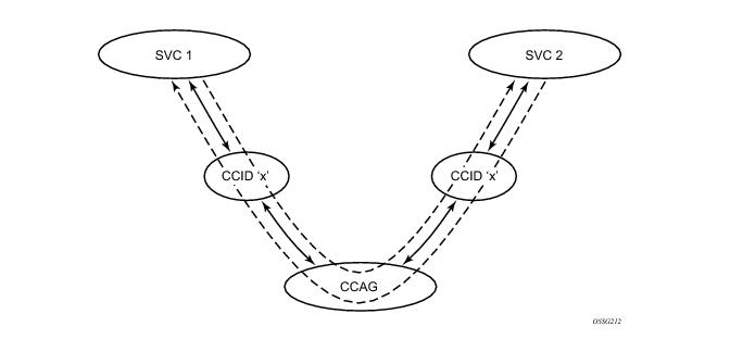
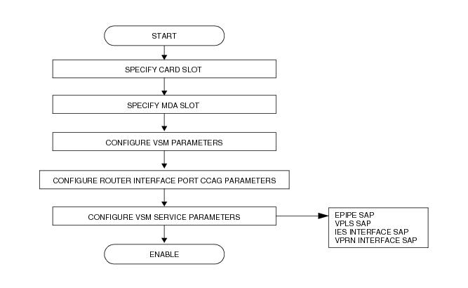
In many instances, it is desirable to process a stream of packets from one or more subscribers through multiple features that, for one reason or another, are mutually exclusive in the 7750 SR forwarding planes. For example, multiple subscriber sites could be bridged together through a VPLS instance while requiring in-service high speed Internet access (IES). Functionality of this type can be handled several ways:
For the purpose exploring each of these solutions, the VPLS and IES service interconnection scenario is examined.
 
Multiple System Solution
The multiple system (meaning multiple boxes) solution splits the functionality between two distinct nodes. The first node performs the VPLS bridging functions while maintaining per site QoS and accounting functions. The second node connects to the first node as a destination in the VPLS service. This connection could be configured as a SAP to SAP or a pseudo-wire spoke connection.
 
Hybrid Service Solution
The hybrid solution merges the two services into a single, common service. This can be accomplished for our example service interconnect by either supporting a virtual IP interface in the context of a VPLS service or providing an IP-only solution that provides for multiple SAPs on a single IES IP interface.
The hybrid solution does not provide for separate accounting and QoS for packets forwarded (or routed) between the subscriber sites and the packets routed to next-hops outside the subscriber domain.
 
Single System Multiple Interface Solution
The single system solution retains the same SLA enforcement and accounting capabilities as the multiple system solution but with the advantage of only requiring a single chassis. This is accomplished by defining the VPLS and IES services on different physical interfaces of the same type. Both interfaces are defined as access types and use the same encapsulation type (i.e., Dot1q). The services are configured with the same encapsulation values and the physical interfaces are interconnected using an external jumper cable. To avoid single point of failure issues, Link Aggregation Groups (LAG) can be used to provide an N-to-1 redundancy mechanism (as well as adding more interconnect bandwidth).
 
Full Feature Internal Service Cross Connect Solution
The internal service cross connect solution provides similar functionality as the single system multiple interface solution while attempting to minimize the cost, density and provisioning issues inherent to the external port jumper method. The internal service cross connection feature uses new service provisioning objects and a new type of hardware adapter to manage internal service cross connections. The remainder of this document describes the internal service cross connection feature.
Functional Components
The internal service cross connection feature uses an adapter designed to fit within an IOM (Input Output Module) MDA (Media Dependant Adapter) slot. There are two types of adapters the VSM-CCA and the new VSM-CCA-XP which supports all of the features of the VSM-CCA but allows for a new higher capacity mode. One or more adapters are placed into a cross connect aggregation group (CCAG). To cross connect two services, each service is bound to the same cross connect aggregation group using the same cross connection identifier. This section introduces each object and gives a brief explanation of its function.
 
Service Cross Connect Adapter (CCA)
The VSM Cross Connect Adapter (CCA) is a type of MDA for 7750 SR platforms designed to provide an egress to ingress forwarding plane interconnection. When a CCA is installed in an MDA slot, a set of virtual ports is available to the system providing the ability to extend packet processing through an extra set of egress and ingress forwarding paths that CCA interfaces.
Unlike external port connections which utilize two TX-RX paths, a CCA interconnects the egress forwarding path on the IOM directly to the ingress forwarding path. This eliminates the need for the physical port MAC, PHY, cable and other MDA-specific components producing a less costly and more reliable adapter. The complete 10G+ forwarding path is available allowing single conversations up to 10G.
Bandwidth is utilized more efficiently than with externally cabled ports. Typically, the offered load presented to each side of the cross-connect port-pair is asymmetric in nature. When physical ports are used to cross connect services, each service is egress bandwidth-limited to the link speed of the TX-RX path.
If one TX-RX path is under-utilized, egress services on the other path cannot make use of the available bandwidth. Since the CCA is forwarding all services over the same path, all the available bandwidth can be used.
The forwarding plane that the CCA interconnects maintains the complete egress and ingress features of the services it is interconnecting. This includes the ability to remap QoS, enforce policing and shaping, and provide ingress and egress accounting for each service.
 
Internal Service CCAG
VSM CCAs are placed in a CCAG. A CCAG provides a mechanism to aggregate multiple CCAs into a single forwarding group. The CCAG uses conversation hashing to dynamically distribute cross-connect traffic to the active CCAs in the aggregation group. In the event that an active CCA fails or is removed from the group, the conversation hashing function redistributes the traffic over the remaining active CCAs within the group.
The conversation hashing mechanism performed for a CCAG is identical to the hashing functions performed for Ethernet LAGs (Link Aggregation Groups).
 
Internal Service Cross Connect Identifier (CCID)
Services and IP interfaces are bound to a CCAG through a CCID (Cross Connect Identifier). When two services or a service and an IP interface are assigned the same CCID the CCAG attempts to provide a cross connection path between the objects. The CCID enables multiple pairs of cross connected services to share the same CCAG.
Figure 114: Internal Service Interconnection Using CCID
From a service perspective, a CCID is an object that not only binds two services together, but also provides the attachment point for the ingress and egress QoS, filtering, and accounting parameters. When considered in conjunction with the CCAG, it allows the actual cross connection path (through the CCAs) to be indirectly associated with the services using the CCAG and maintains a simplified provisioning model over port level cross connected services.
 
CCAG Bandwidth and Resiliency
A CCAG is an intermediate object between cross-connected objects (SAPs and network IP interfaces) and the CCAs. A CCAG is similar to a Link Aggregation Group (LAG) of Ethernet ports and uses the same underlying mechanisms to distribute conversations over multiple CCAs and converge when a CCA becomes active or inactive in the group.
When a CCAG is created, the system allocates six Ethernet LAGs for the virtual ports on the CCAs placed into the group. Each virtual port is placed into a respective LAG. For instance, each time a CCA is placed into the CCAG, virtual port 1 on that CCA is placed into the first LAG allocated to that CCAG. Virtual port 2 is placed into the second LAG on the CCAG. Virtual ports 3 through 6 are placed into their respective LAGs as well.
Using the set of LAGs provides a mechanism for conversation hashing or service mapping over all member CCAs in the CCAG. In the unlikely event that a CCA fails or is removed from the CCAG, the system will automatically modify the conversation hashing or service mapping on the CCAG to represent the available active CCAs.
 
CCAG LAG Attributes
Unlike a user-provisioned LAG, the internal LAGs do not use a primary member to control the typical port level configuration parameters. Instead, the parameters usually found at the port level are implemented directly on the CCAG internal LAG representative objects (sap-sap, sap-net and net-sap) for each path. These commands perform functions such as MTU definition and locally administering the MAC address.
The default unique MAC addresses used each internal LAG within the CCAG are automatically assigned from the chassis MAC pool. These MAC addresses are assigned from the pool based on an offset relative to the CCAG-ID. The same set of default MAC addresses are assigned each time a specific CCAG-ID is created.
Although a CCAG uses internal LAG mechanisms, the LACP protocol is not supported or required. LAG resources used for CCAG purposes are not exposed to the user.
 
CCAG Traffic Distribution
A CCAG uses both direct object mapping and conversation hashing to distribute traffic over multiple CCAs. To understand how each object type’s ingress traffic is distributed over the active CCAs in a CCAG, refer to the LAG and ECMP Hashing section of the 7750 SR OS Interface Configuration Guide.
 
CCAG SAP QoS
When a SAP is created on a CCAG, the service queues defined by the ingress and egress QoS policy are created on each CCA member in the CCAG. Packets are forwarded to the egress queues based on the hashing or service mapping enforced by the LAG functions internal to the system. Packets are received on a CCA ingress queue based on which CCA handled the egress processing. Each ingress and egress hardware queue buffering and rate parameters are managed by the system based on one of two models governed by the state of the LAG QoS adaptation setting. The adaptation state also governs the application of hierarchical virtual schedulers associated with the SAP queues.
 
Link Level CCAG SAP QoS Adaptation
Link level QoS adaptation is set when the CCA access QoS adaptation flag is set to link. Link-level distribution informs the system that a service queue’s buffering and rate parameters should be applied directly to each hardware queue representing the service queue. For example, when a service queue is configured with a rate equal to 10Mbps, each corresponding CCA hardware queue will be configured with a rate of 10Mbps. Given many flows conversation hashing to different CCAs, the maximum forwarded rate will be the 10Mbps multiplied by the number of active CCAs.
When a link-level adaptation service queue is a child to a parent virtual scheduler, the parent scheduler and the rest of the scheduler hierarchy is implemented per CCA. An instance of the scheduler policy is maintained per CCA.
When a CCAG SAP is a member of a Multi-Service Site (MSS), all SAPs in the MSS must be CCAG SAPs created on the same CCAG-ID.
 
Distributed CCAG SAP QoS Adaptation
Distributed QoS adaptation is set when the CCA access QoS adaptation flag is set to distribute. The distributed QoS parameter setting informs the system that a service queue’s buffering and rate parameters should be distributed between the active CCAs in the CCAG. For example, when a service queue is configured with a rate equal to 10Mbps and two CCAs are active in the CCAG, each corresponding CCA hardware queue will be configured with a rate of 5Mbps (1/2 of the provisioned service queue parameters). Given many flows conversation hashing to different CCAs, the maximum forwarded rate will be limited to 10Mbps.
When a distributed adaptation service queue is a child to a parent virtual scheduler, the parent scheduler and the rest of the scheduler hierarchy is implemented on each IOM with an active member CCA from the CCAG. The scheduler parameters are divided amongst the IOMs with active CCAs based on the total number of active CCAs. If there are three active CCAs in the CCAG, each CCA represents 1/3 of rate and CIR defined for each scheduler in the policy. If two of the active CCAs are on one IOM and one active CCA is on a second IOM, the first IOM would receive 2/3 of the rate and CIR for each scheduler and the second IOM would receive 1/3. The overall distribution is based on the following equation:
IOM Scheduler Rate = Policy Scheduler Rate * (Number Active CCAs on IOM / Total Active CCAs)
IOM Scheduler CIR = Policy Scheduler CIR * (Number Active CCAs on IOM / Total Active CCAs)
When a CCAG SAP is a member of a multi-service site, all SAPs in the multi-service site must be CCAG SAPs created on the same CCAG-ID.
 
VSM-CCA-XP
In addition to supporting all the features of the existing VSM-CCA, the new VSM-CCA-XP MDA offers a new hybrid mode for simplified provisioning and a higher capacity VSM when inserted on IOM3 cards. As with the VSM-CCA MDA the complete forwarding path bandwidth (in this case 25G) is available allowing single conversations up to 25G on a single MDA.
The uses cases for VSM-CCA-XP are nearly identical to the VSM-CCA. When configured as a VSM-CCA-XP port x/x1 and port x/x/2 are internally connected. Therefore configuration is very similar to a physical loop back port using Ethernet with dot1Q encapsulation. The use of hybrid port removes the requirement to configure net and sap parameters and simplifies provisioning. The use of the Ethernet VLAN Tag is used to connect the SAPs.
VSM-CCA-XP Exceptions:
The new VSM-CCA-XP can be configured as a VSM-CCA MDA to support CCA functions on IOM1, IOM2 and IOM3. On IOM3 the VSM-CCA MDA supports a loop back mode that uses LAG and 2 ports using Ethernet as the internal connection. The LAG feature also conversations hashing just as the original VSM-CCA. The hybrid port mode eliminates the need to specify network or access modes.
Sample Configuration for MDA. Normally when a VSM-CCA-XP MDA is inserted it may be configured as a VSM-CCA or a VSM-CCA-XP.
===============================================================================
MDA Summary
===============================================================================
Slot  Mda   Provisioned           Equipped              Admin     Operational
            Mda-type              Mda-type              State     State
-------------------------------------------------------------------------------
1     1     vsm-cca               vsm-cca-xp               up        up
      2     vsm-cca-xp            vsm-cca-xp               up        up
===============================================================================
    card 1
        mda 2
            mda-type vsm-cca-xp
            no shutdown
        exit
    exit
Sample VSM-CCM-XP Configuration for Ports:
    port 1/2/1
        ethernet
        exit
        no shutdown
    exit
    port 1/2/2
        ethernet
        exit
        no shutdown
    exit
Port and Ethernet QoS parameters may be configured as with physical port. The Ethernet on VSM-CCA-XP has a reduced set of features. For example dot1Q is the only supported encapsulation. LACP cannot be configured on LAGs using the port.
The ports may be used directly by service SAP in the case of a single loop back. If resiliency desired, or more capacity is needed, a LAG can be configured.
Sample Configuration for LAG on a single VSM-CCA-XP MDA:
    lag 1
        mode hybrid
        encap-type dot1q
        port 1/2/1 // VSM-CCA-XP
        no shutdown
    exit
    lag 2
        mode hybrid
        encap-type dot1q
        port 1/2/2 // VSM-CCA-XP
        no shutdown
    exit
The following is a sample for an VPLS service equivalent using the LAG port.
  vpls 121 customer 1 create
     stp
         shutdown
     exit
     sap lag-1:1001 create // Connect using VLAN Tag 1001
     exit
     no shutdown
     ...
 exit
The following is a sample for an IES service equivalent to the configuration.
 ies 122 customer 1 create
     interface "Loopback" create
         address 8.1.1.1/24
         sap lag-2:1001 create
             ingress
                qos 3
             exit
             egress
                 qos 1010
             exit
         exit
     exit
     ...
     no shutdown
exit
A VSM-CCA-XP may be configured as either a VSM-CCA MDA or a VSM-CCA-XP MDA. When configured as a VSM-CCA-XP it is not a member of a CCA Group (ref VSM-CCA-XP).
Configuration Process Overview
Figure 115 displays the process to provision VSM parameters.
Figure 115: VSM/CCAG Configuration and Implementation Flow
Configuration Notes
The following information describes provisioning caveats: