For feedback and comments:
documentation.feedback@alcatel-lucent.com

Table of Contents Previous Next Index PDF


IEEE 802.1ah Provider Backbone Bridging
In This Chapter
This chapter provides information about Provider Backbone Bridging (PBB), process overview, and implementation notes.
Topics in this chapter include:
IEEE 802.1ah Provider Backbone Bridging (PBB) Overview
IEEE 802.1ah draft standard (IEEE802.1ah), also known as Provider Backbone Bridges (PBB), defines an architecture and bridge protocols for interconnection of multiple Provider Bridge Networks (PBNs - IEEE802.1ad QinQ networks). PBB is defined in IEEE as a connectionless technology based on multipoint VLAN tunnels. IEEE 802.1ah employs Provider MSTP as the core control plane for loop avoidance and load balancing. As a result, the coverage of the solution is limited by STP scale in the core of large service provider networks.
Virtual Private LAN Service (VPLS), RFC 4762, Virtual Private LAN Service (VPLS) Using Label Distribution Protocol (LDP) Signaling, provides a solution for extending Ethernet LAN services using MPLS tunneling capabilities through a routed, traffic-engineered MPLS backbone without running (M)STP across the backbone. As a result, VPLS has been deployed on a large scale in service provider networks.
Alcatel-Lucent’s implementation fully supports a native PBB deployment and an integrated PBB-VPLS model where desirable PBB features such as MAC hiding, service aggregation and the service provider fit of the initial VPLS model are combined to provide the best of both worlds.
PBB Features
 
Integrated PBB-VPLS Solution
HVPLS introduced a service-aware device in a central core location in order to provide efficient replication and controlled interaction at domain boundaries. The core network facing provider edge (N-PE) devices have knowledge of all VPLS services and customer MAC addresses for local and related remote regions resulting in potential scalability issues as depicted in Figure 82.
 
Figure 82: Large HVPLS Deployment
In a large VPLS deployment, it is important to improve the stability of the overall solution and to speed up service delivery. These goals are achieved by reducing the load on the N-PEs and respectively minimizing the number of provisioning touches on the N-PEs.
The integrated PBB-VPLS model introduces an additional PBB hierarchy in the VPLS network to address these goals as depicted in Figure 83.
 
Figure 83: Large PBB-VPLS Deployment
PBB encapsulation is added at the user facing PE (U-PE) to hide the customer MAC addressing and topology from the N-PE devices. The core N-PEs need to only handle backbone MAC addressing and do not need to have visibility of each customer VPN. As a result, the integrated PBB-VPLS solution decreases the load in the N-PEs and improves the overall stability of the backbone.
Alcatel-Lucent’s PBB-VPLS solution also provides automatic discovery of the customer VPNs through the implementation of IEEE 802.1ak MMRP minimizing the number of provisioning touches required at the N-PEs.
 
PBB Technology
IEEE 802.1ah specification encapsulates the customer or QinQ payload in a provider header as shown in Figure 84.
Figure 84: QinQ Payload in Provider Header Example
PBB adds a regular Ethernet header where the B-DA and B-SA are the backbone destination and respectively, source MACs of the edge U-PEs. The backbone MACs (B-MACs) are used by the core N-PE devices to switch the frame through the backbone.
A special group MAC is used for the backbone destination MAC (B-DA) when handling an unknown unicast, multicast or broadcast frame. This backbone group MAC is derived from the I-service instance identifier (ISID) using the rule: a standard group OUI (01-1E-83) followed by the 24 bit ISID coded in the last three bytes of the MAC address.
The BVID (backbone VLAN ID) field is a regular DOT1Q tag and controls the size of the backbone broadcast domain. When the PBB frame is sent over a VPLS pseudo-wire (pseudowire), this field may be omitted depending on the type of pseudowire used.
The following ITAG (standard Ether-type value of 0x88E7) has the role of identifying the customer VPN to which the frame is addressed through the 24 bit ISID. Support for service QoS is provided through the priority (3 bit I-PCP) and the DEI (1 bit) fields.
 
PBB Mapping to Existing VPLS Configurations
The IEEE model for PBB is organized around a B-component handling the provider backbone layer and an I-component concerned with the mapping of the customer/provider bridge (QinQ) domain (MACs, VLANs) to the provider backbone (B-MACs, B-VLANs): for example, the I-component contains the boundary between the customer and backbone MAC domains.
Alcatel-Lucent’s implementation is extending the IEEE model for PBB to allow support for MPLS pseudowires using a chain of two VPLS context linked together as depicted in Figure 85.
 
Figure 85: PBB Mapping to VPLS Constructs
A VPLS context is used to provide the backbone switching component. The white circle marked B, referred to as backbone-VPLS (B-VPLS), operates on backbone MAC addresses providing a core multipoint infrastructure that may be used for one or multiple customer VPNs. Alcatel-Lucent’s B-VPLS implementation allows the use of both native PBB and MPLS infrastructures.
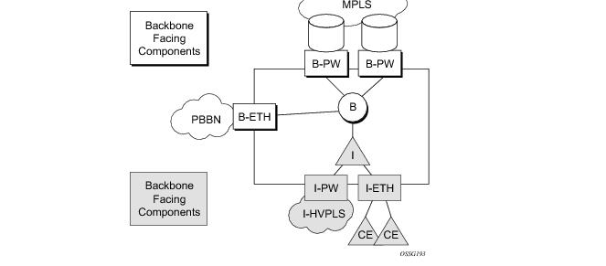
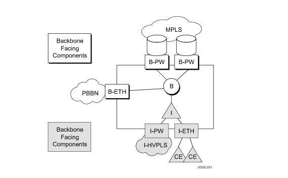
Another VPLS context (I-VPLS) can be used to provide the multipoint I-component functionality emulating the ELAN service (refer to the triangle marked “I” in Figure 85). Similar to B-VPLS, I-VPLS inherits from the regular VPLS the pseudowire (SDP bindings) and native Ethernet (SAPs) handoffs accommodating this way different types of access: for example, direct customer link, QinQ or HVPLS.
In order to support PBB ELINE (point-to-point service), the use of an Epipe as I-component is allowed. All Ethernet SAPs supported by a regular Epipe are also supported in the PBB Epipe.
 
SAP and SDP Support
 
PBB B-VPLS
 
PBB I-VPLS
Existing SAP processing rules still apply for the I-VPLS case; the SAP encapsulation definition on Ethernet ingress ports defines which VLAN tags are used to determine the service that the packet belongs to:
I-VPLS services do not support the forwarding of PBB encapsulated frames received on SAPs or Spoke-SDPs through their associated B-VPLS service. PBB frames are identified based on the configured PBB Ethertype (0x88e7 by default).
 
PBB Packet Walkthrough
This section describes the walkthrough for a packet that traverses the B-VPLS and I-VPLS instances using the example of a unicast frame between two customer stations as depicted in the following network diagram Figure 86.
 
Figure 86: PBB Packet Walkthrough
The station with CMAC (customer MAC) X wants to send a unicast frame to CMAC Y through the PBB-VPLS network. A customer frame arriving at PBB-VPLS U-PE1 is encapsulated with the PBB header. The local I-VPLS FIB on U-PE1 is consulted to determine the destination BMAC of the egress U-PE for CMAC Y. In our example, B2 is assumed to be known as the B-DA for Y. If CMAC Y is not present in the U-PE1 forwarding database, the PBB packet is sent in the B-VPLS using the standard group MAC address for the ISID associated with the customer VPN. If the uplink to the N-PE is a spoke pseudowire, the related PWE3 encapsulation is added in front of the B-DA.
Next, only the Backbone Header in green is used to switch the frame through the green B-VPLS/VPLS instances in the N-PEs. At the receiving U-PE2, the CMAC X is learned as being behind BMAC B1; then the PBB encapsulation is removed and the lookup for CMAC Y is performed. In the case where a pseudowire is used between N-PE and U-PE2, the pseudowire encapsulation is removed first.
 
PBB Control Planes
PBB technology can be deployed in a number of environments. Natively, PBB is an Ethernet data plane technology that offers service scalability and multicast efficiency.
Environment:
Within these environments, SR OS offers a number of optional control planes:
In general a control plane is required on Ethernet SAPs, or SDPs where there could be physical loops. Some network configurations of Mesh and Spoke SDPs can avoid physical loops and no control plane is required.
The choice of control plane is based on the requirement of the networks. SPBM for PBB offers a scalable link state control plane without BMAC flooding and learning or MMRP. RSTP and MSTP offer Spanning tree options based on BMAC flooding and learning. MMRP is used with flooding and learning to improve multicast.
Shortest Path Bridging MAC Mode (SPBM)
Shortest Path Bridging (SPB) enables a next generation control plane for PBB based on IS-IS that adds the stability and efficiency of link state to unicast and multicast services. Specifically this is an implementation of SPBM (SPB MAC mode). Current SR OS PBB B-VPLS offers point to point and multipoint to multipoint services with large scale. PBB B-VPLS is deployed in both Ethernet and MPLS networks supporting Ethernet VLL and VPLS services. SPB removes the flooding and learning mode from the PBB Backbone network and replaces MMRP for ISID Group Mac Registration providing flood containment. SROS SPB provides true shortest path forwarding for unicast and efficient forwarding on a single tree for multicast. It supports selection of shortest path equal cost tie-breaking algorithms to enable diverse forwarding in an SPB network.
 
Flooding and Learning Versus Link State
SPB brings a link state capability that improves the scalability and performance for large networks over the xSTP flooding and learning models. Flooding and learning has two consequences. First, a message invoking a flush must be propagated, second the data plane is allowed to flood and relearn while flushing is happening. Message based operation over these data planes may experience congestion and packet loss.
 
Link state operates differently in that only the information that truly changes needs to be updated. Traffic that is not affected by a topology change does not have to be disturbed and does not experience congestion since there is no flooding. SPB is a link state mechanism that uses restoration to reestablish the paths affected by topology change. It is more deterministic and reliable than RSTP and MMRP mechanisms. SPB can handle any number of topology changes and as long as the network has some connectivity, SPB will not isolate any traffic.
SPB for B-VPLS
The SROS model supports PBB Epipes and I-VPLS services on the B-VPLS. SPB is added to B-VPLS in place of other control planes (see Table 15). SPB runs in a separate instance of IS-IS. SPB is configured in a single service instance of B-VPLS that controls the SPB behavior (via IS-IS parameters) for the SPB IS-IS session between nodes. Up to four independent instances of SPB can be configured. Each SPB instance requires a separate control B-VPLS service. A typical SPB deployment uses a single control VPLS with zero, one or more user B-VPLS instances. SPB is multi-topology (MT) capable at the IS-IS LSP TLV definitions however logical instances offer the nearly the same capability as MT. The SROS SPB implementation always uses MT topology instance zero. Area addresses are not used and SPB is assumed to be a single area. SPB must be consistently configured on nodes in the system. SPB Regions information and IS-IS hello logic that detect mismatched configuration are not supported.
SPB Link State PDUs (LSPs) contains BMACs, I-SIDs (for multicast services) and link and metric information for an IS-IS database. Epipe I-SIDs are not distributed in SROS SPB allowing high scalability of PBB Epipes. I-VPLS I-SIDs are distributed in SROS SPB and the respective multicast group addresses are automatically populated in forwarding in a manner that provides automatic pruning of multicast to the subset of the multicast tree that supports I-VPLS with a common I-SID. This replaces the function of MMRP and is more efficient than MMRP so that in the future SPB will scale to a greater number of I-SIDs.
SPB on SROS can leverage MPLS networks or Ethernet networks or combinations of both. SPB allows PBB to take advantage of multicast efficiency and at the same time leverage MPLS features such as resiliency.
 
Control B-VPLS and User B-VPLS
Control B-VPLS are required for the configuration of the SPB parameters and as a service to enable SPB. Control B-VPLS therefore must be configured everywhere SPB forwarding is expected to be active even if there are no terminating services. SPB uses the logical instance and a Forwarding ID (FID) to identify SPB locally on the node. The FID is used in place of the SPB VLAN identifier (Base VID) in IS-IS LSPs enabling a reference to exchange SPB topology and addresses. More specifically, SPB advertises B-MACs and I-SIDs in a B-VLAN context. Since the service model in SROS separates the VLAN Tag used on the port for encapsulation from the VLAN ID used in SPB the SPB VLAN is a logical concept and is represented by configuring a FID. B-VPLS SAPs use VLAN Tags (SAPs with Ethernet encapsulation) that are independent of the FID value. The encapsulation is local to the link in SR/ESS so the SAP encapsulation has be configured the same between neighboring switches. The FID for a given instance of SPB between two neighbor switches must be the same. The independence of VID encapsulation is inherent to SROS PBB B-VPLS. This also allows spoke SDP bindings to be used between neighboring SPB instances without any VID tags. The one exception is mesh SDPs are not supported but arbitrary mesh topologies are supported by SROS SPB.
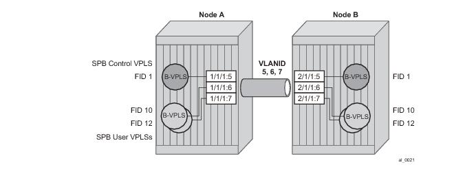
Figure 87 illustrates two switches where an SPB control B-VPLS configured with FID 1 and uses a SAP with 1/1/1:5 therefore using a VLAN Tag 5 on the link. The SAP 1/1/1:1 could also have been be used but in SROS the VID does not have to equal FID. Alternatively an MPLS PW (spoke SDP binding) could be for some interfaces in place of the SAP. Figure 87 illustrates a control VPLS and two user B-VPLS. The User B-VPLS must share the same topology and are required to have interfaces on SAPs/Spoke SDPs on the same links or LAG groups as the B-VPLS. To allow services on different B-VPLS to use a path when there are multiple paths a different ECT algorithm can be configured on a B-VPLS instance. In this case, the user B-VPLS still fate shared the same topology but they may use different paths for data traffic; see Shortest Path and Single Tree .
Figure 87: Control and User B-VPLS with FIDs
Each user BVPLS offers the same service capability as a control B-VPLS and are configured to “follow” or fate share with a control B-VPLS. User B-VPLS must be configured as active on the whole topology where control B-VPLS is configured and active. If there is a mismatch between the topology of a user B-VPLS and the control B-VPLS, only the user B-VPLS links and nodes that are in common with the control B-VPLS will function. The services on any B-VPLS are independent of a particular user B-VPLS so a mis-configuration of one of the user B-VPLS will not affect other B-VPLS. For example if a SAP or spoke SDP is missing in the user B-VPLS any traffic from that user B-VPLS that would use that interface, will be missing forwarding information and traffic will be dropped only for that B-VPLS. The computation of paths is based only on the control B-VPLS topology.
User B-VPLS instances supporting only unicast services (PBB-Epipes) may share the FID with the other B-VPLS (control or user). This is a configuration short cut that reduces the LSP advertisement size for B-VPLS services but results in the same separation for forwarding between the B-VPLS services. In the case of PBB-Epipes only BMACs are advertised per FID but BMACs are populated per B-VPLS in the FIB. If I-VPLS services are to be supported on a B-VPLS that B-VPLS must have an independent FID.
Shortest Path and Single Tree
IEEE 802.1aq standard SPB uses a source specific tree model. The standard model is more computationally intensive for multicast traffic since in addition to the SPF algorithm for unicast and multicast from a single node, an all pairs shorted path needs to be computed for other nodes in the network. In addition, the computation must be repeated for each ECT algorithm. While the standard yields efficient shortest paths, this computation is overhead for systems where multicast traffic volume is low. Ethernet VLL and VPLS unicast services are popular in PBB networks and the SROS SPB design is optimized for unicast delivery using shortest paths. Ethernet supporting unicast and multicast services are commonly deployed in Ethernet transport networks. SROS SPB Single tree multicast (also called shared tree or *,G) operates similarly today. The difference is that SPB multicast never floods unknown traffic.
The SR OS implementation of SPB with shortest path unicast and single tree multicast, requires only two SPF computations per topology change reducing the computation requirements. One computation is for unicast forwarding and the other computation is for multicast forwarding.
A single tree multicast requires selecting a root node much like RSTP. Bridge priority controls the choice of root node and alternate root nodes. The numerically lowest Bridge Priority is the criteria for choosing a root node. If multiple nodes have the same Bridge Priority, then the lowest Bridge Identifier (System Identifier) is the root.
In SPB the source-bmac can override the chassis-mac allowing independent control of tie breaking, The shortest path unicast forwarding does not require any special configuration other than selecting the ECT algorithm by configuring a B-VPLS use a FID with low-path-id algorithm or high-path-id algorithm to tie break between equal cost paths. Bridge priority allows some adjustment of paths. Configuring link metrics adjusts the number of equal paths.
To illustrate the behavior of the path algorithms a sample network is shown in Figure 88.
Figure 88: Sample Partial Mesh network
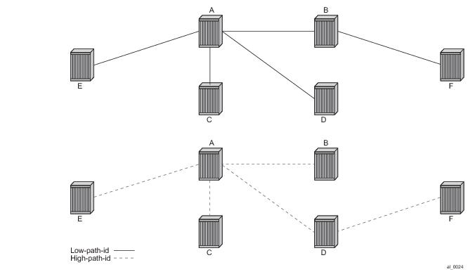
Assume that Node A is the lowest Bridge Identifier and the Multicast root node and all links have equal metrics. Also, assume that Bridge Identifiers are ordered such that Node A has a numerically lower Bridge identifier than Node B, and Node B has lower Bridge Identifier than Node C, etc. Unicast paths are configured to use shortest path tree (SPT). Figure 89 shows the shortest paths computed from Node A and Node E to Node F. There are only two shortest paths from A to F. A choice of low-path-id algorithm uses Node B as transit node and a path using high-path-id algorithm uses Node D as transit node. The reverse paths from Node F to A are the same (all unicast paths are reverse path congruent). For Node E to Node F there are three paths E-A-B-F, E-A-D-F, and E-C-D-F. The low-path-id algorithm uses path E-A-B-F and the high-path-id algorithm uses E-C-D-F. These paths are also disjoint and are reverse path congruent. Note that any nodes that are directly connected in this network have only one path between them (not shown for simplicity).
Figure 89: Unicast Paths for Low-path-id and High-path-id
For Multicast paths the algorithms used are the same low-path-id or high-path-id but the tree is always a single tree using the root selected as described earlier (in this case Node A). Figure 90 illustrates the multicast paths for low-path-id and high-path-id algorithm.
Figure 90: Multicast Paths for Low-path-id and High-path-id
All nodes in this network use one of these trees. Note that the path for multicast to/from Node A is the same as unicast traffic to/from Node A for both low-path-id and high-path-id. However, the multicast path for other nodes is now different from the unicast paths for some destinations. For example, Node E to Node F is now different for high-path-id since the path must transit the root Node A. In addition, the Node E multicast path to C is E-A-C even though E has a direct path to Node C. A rule of thumb is that the node chosen to be root should be a well-connected node and have available resources. In this example, Node A and Node D are the best choices for root nodes.
The distribution of I-SIDs allows efficient pruning of the multicast single tree on a per I-SID basis since only MFIB entries between nodes on the single tree are populated. For example, if Nodes A, B and F share an I-SID and they use the low-path–id algorithm only those three nodes would have multicast traffic for that I-SID. If the high-path-id algorithm is used traffic from Nodes A and B must go through D to get to Node F.
 
Data Path and Forwarding
The implementation of SPB on SROS uses the PBB data plane. There is no flooding of BMAC based traffic. If a BMAC is not found in the FDB, traffic is dropped until the control plane populates that BMAC. Unicast BMAC addresses are populated in all FDBs regardless of I-SID membership. There is a unicast FDB per B-VPLS both control B-VPLS and user BVPLS. B-VPLS instances that do not have any I-VPLS, have only a default multicast tree and do not have any multicast MFIB entries.
The data plane supports an ingress check (reverse path forwarding check) for unicast and multicast frames on the respective trees. Ingress check is performed automatically. For unicast or multicast frames the BMAC of the source must be in the FDB and the interface must be valid for that BMAC or traffic is dropped. The PBB encapsulation (See PBB Technology) is unchanged from current SROS. Multicast frames use the PBB Multicast Frame format and SPBM distributes I-VPLS I-SIDs which allows SPB to populate forwarding only to the relevant branches of the multicast tree. Therefore, SPB replaces both spanning tree control and MMRP functionality in one protocol.
By using a single tree for multicast the amount of MFIB space used for multicast is reduced. (Per source shortest path trees for multicast are not currently offered on SROS.) In addition, a single tree reduces the amount of computation required when there is topology change.
 
SPB Ethernet OAM
Ethernet OAM works on Ethernet services and use a combination of unicast with learning and multicast addresses (REF to OAM section). SPB on SROS supports both unicast and multicast forwarding, but with no learning and unicast and multicast may take different paths. In addition, SROS SPB control plane offers a wide variety of show commands. The SPB IS-IS control plane takes the place of many Ethernet OAM functions. SPB IS-IS frames (Hello and PDU etc) are multicast but they are per SPB interface on the control B-VPLS interfaces and are not PBB encapsulated.
All Client Ethernet OAM is supported from I-VPLS interfaces and PBB Epipe interfaces across the SPB domain. Client OAM is the only true test of the PBB data plane. The only forms of Eth-OAM supported directly on SPB B-VPLS are Virtual MEPS (vMEPs). Only CCM is supported on these vMEPs; vMEPs use a S-TAG encapsulation and follow the SPB multicast tree for the given B-VPLS. Each MEP has a unicast associated MAC to terminate various ETH-CFM tools. However, CCM messages always use a destination Layer 2 multicast using 01:80:C2:00:00:3x (where x = 0..7). vMEPs terminate CCM with the multicast address. Unicast CCM can be configured for point to point associations or hub and spoke configuration but this would not be typical (when unicast addresses are configured on vMEPs they are automatically distributed by SPB in IS-IS).
Up MEPs on services (I-VPLS and PBB Epipes) are also supported and these behave as any service OAM. These OAM use the PBB encapsulation and follow the PBB path to the destination.
Link OAM or 802.1ah EFM is supported below SPB as standard. This strategy of SPB IS-IS and OAM gives coverage.
 
In summary SPB offers an automated control plane and optional Eth-CFM/Eth-EFM to allow monitoring of Ethernet Services using SPB. B-VPLS services PBB Epipes and I-VPLS services support the existing set of Ethernet capabilities
 
SPB Levels
Levels are part of IS-IS. SPB supports Level 1 within a control B-VPLS. Future enhancements may make use of levels.
SPBM to Non-SPBM Interworking
By using static definitions of B-MACs and ISIDs interworking of PBB Epipes and I-VPLS between SPBM networks and non SPBM PBB networks can be achieved.
 
Static MACs and Static ISIDs
To extend SPBM networks to other PBB networks, static MACs and ISIDs can be defined under SPBM SAPs/SDPs. The declaration of a static MAC in an SPBM context allows a non-SPBM PBB system to receive frames from an SPBM system. These static MACs are conditional on the SAP/SDP operational state. (Currently this is only supported for SPBM since SPBM can advertise these BMACs and ISIDs without any requirement for flushing.) The BMAC (and BMAC to ISID) must remain consistent when advertised in the IS-IS database.
The declaration of static-isids allows an efficient connection of ISID based services. The ISID is advertised as supported on the local nodal BMAC and the static BMACs which are the true destinations for the ISIDs are also advertised. When the I-VPLS learn the remote BMAC they will associated the ISID with the true destination BMAC. Therefore if redundancy is used the BMACs and ISIDs that are advertised must be the same on any redundant interfaces.
If the interface is an MC-LAG interface the static MAC and ISIDs on the SAPs/SDPs using that interface are only active when the associated MC-LAG interface is active. If the interface is a spoke SDP on an active/ standby pseudo wire (PW) the ISIDs and BMACs are only active when the PW is active.
 
Epipe Static Configuration
For Epipe only, the BMACs need to be advertised. There is no multicast for PBB epipes. Unicast traffic will follow the unicast path shortest path or single tree. By configuring remote BMACs Epipes can be setup to non SPBM systems. A special conditional static-mac is used for SPBM PBB B-VPLS SAPs/SDPs that are connected to a remote system. In the diagram ISID 500 is used for the PBB Epipe but only conditional MACs A and B are configured on the MC-LAG ports. The B-VPLS will advertise the static MAC either always or optionally based on a condition of the port forwarding.
 
Figure 91: Static MACs Example
 
I-VPLS Static Config
I-VPLS static config consists of two components: static-mac and static ISIDs that represent a remote BMAC-ISID combination.
The static-MACs are configured as with Epipe, the special conditional static-mac is used for SPBM PBB B-VPLS SAPs/SDPs that are connected to a remote system. The B-VPLS will advertise the static MAC either always or optionally based on a condition of the port forwarding.
The static-isids are created under the B-VPLS SAP/SDPs that are connected to a non-SPBM system. These ISIDs are typically advertised but may be controlled by ISID policy.
For I-VPLS ISIDs the ISIDs are advertised and multicast MAC are automatically created using PBB-OUI and the ISID. SPBM supports the pruned multicast single tree. Unicast traffic will follow the unicast path shortest path or single tree. Multicast/and unknown Unicast follow the pruned single tree for that ISID.
 
Figure 92: Static ISIDs Example
 
SPBM ISID Policies
Note that ISID policies are an optional aspect of SPBM which allow additional control of ISIDs for I-VPLS. PBB services using SPBM automatically populate multicast for I-VPLS and static-isids. Improper use of isid-policy can create black holes or additional flooding of multicast.
To enable more flexible multicast, ISID policies control the amount of MFIB space used by ISIDs by trading off the default Multicast tree and the per ISID multicast tree. Occasionally customers want services that use I-VPLS that have multiple sites but use primarily unicast. The ISID policy can be used on any node where an I-VPLS is defined or static ISIDs are defined.
The typical use is to suppress the installation of the ISID in the MFIB using use-def-mcast and the distribution of the ISID in SPBM by using no advertise-local.
The use-def-mcast policy instructs SPBM to use the default B-VPLS multicast forwarding for the ISID range. The ISID multicast frame remains unchanged by the policy (the standard format with the PBB OUI and the ISID as the multicast destination address) but no MFIB entry is allocated. This causes the forwarding to use the default BVID multicast tree which is not pruned. When this policy is in place it only governs the forwarding locally on the current B-VPLS.
The advertise local policy ISID policies are applied to both static ISIDs and I-VPLS ISIDs. The policies define whether the ISIDs are advertised in SPBM and whether the use the local MFIB. When ISIDs are advertised they will use the MFIB in the remote nodes. Locally the use of the MFIB is controlled by the use-def-mcast policy.
The types of interfaces are summarized in Table 17.
 
 
ISID Policy Control
 
Static ISID Advertisement
Static ISIDs are advertised between using the SPBM Service Identifier and Unicast Address sub-TLV in IS-IS when there is no ISID policy. This TLV advertises the local B-MAC and one or more ISIDs. The BMAC used is the source-bmac of the Control/User VPLS. Typically remote BMACs (the ultimate source-bmac) and the associated ISIDs are configured as static under the SPBM interface. This allows all remote BMACs and all remote ISIDs can be configured once per interface.
 
I-VPLS for Unicast Service
If the service is using unicast only an I-VPLS still uses MFIB space and SPBM advertises the ISID. By using the default multicast tree locally, a node saves MFIB space. By using the no advertise-local SPBM will not advertise the ISIDs covered by the policy. Note the actual PBB multicast frames are the same regardless of policy. Unicast traffic is the not changed for the ISID policies.
The Static BMAC configuration is allowed under Multi-Chassis LAG (MC-LAG) based SAPs and active/standby PW SDPs.
Unicast traffic will follow the unicast path shortest path or single tree. By using the ISID policy Multicast/and unknown Unicast traffic (BUM) follows the default B-VPLS tree in the SPBM domain. This should be used sparingly for any high volume of multicast services.
 
Figure 93: ISID Policy Example
 
Default Behaviors
When static ISIDs are defined the default is to advertise the static ISIDs when the interface parent (SAP or SDP) is up.
If the advertisement is not desired, an ISID policy can be created to prevent advertising the ISID.
Each Policy may be used alone or in combination.
 
 
Example Network Configuration
Figure 94: Sample Network
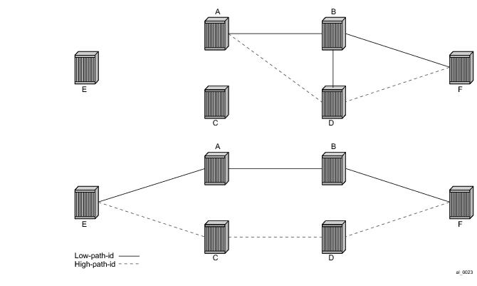
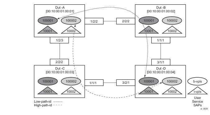
Figure 94 shows an example network showing four nodes with SPB B-VPLS. The SPB instance is configured on the B-VPLS 100001. B-VPLS 100001 uses FID 1 for SPB instance 1024. All BMACs and I-SIDs are learned in the context of B-VPLS 100001. B-VPLS 100001 has an i-vpls 10001 service, which also uses the I-SID 10001. B-VPLS 100001 is configured to use VID 1 on SAPs 1/2/2 and 1/2/3 and while the VID does not need to be the same as the FID the VID does however need to be the same on the other side (Dut-B and Dut-C).
A user B-VPLS service 100002 is configured and it uses B-VPLS 10001 to provide forwarding. It fate shares the control topology. In Figure 94, the control B-VPLS uses the low-path-id algorithm and the user B-VPLS uses high-path-id algorithm. Note that any B-VPLS can use any algorithm. The difference is illustrated in the path between Dut A and Dut D. The short dashed line through Dut-B is the low-path-id algorithm and the long dashed line thought Dut C is the high-path-id algorithm.
Sample Configuration for Dut-A
Dut-A:
Control B-VPLS:*A:Dut-A>config>service>vpls# pwc
-------------------------------------------------------------------------------
Present Working Context :
-------------------------------------------------------------------------------
 <root>
  configure
  service
  vpls "100001"
-------------------------------------------------------------------------------
*A:Dut-A>config>service>vpls# info
----------------------------------------------
            pbb
                source-bmac 00:10:00:01:00:01
            exit
            stp
                shutdown
            exit
            spb 1024 fid 1 create
                level 1
                    ect-algorithm fid-range 100-100 high-path-id
                exit
                no shutdown
            exit
            sap 1/2/2:1.1 create
                spb create
                    no shutdown
                exit
            exit
            sap 1/2/3:1.1 create
                spb create
                    no shutdown
                exit
            exit
            no shutdown
----------------------------------------------
User B-VPLS:
*A:Dut-A>config>service>vpls# pwc
-------------------------------------------------------------------------------
Present Working Context :
-------------------------------------------------------------------------------
 <root>
  configure
  service
  vpls "100002"
-------------------------------------------------------------------------------
*A:Dut-A>config>service>vpls# info
----------------------------------------------
            pbb
                source-bmac 00:10:00:02:00:01
            exit
            stp
                shutdown
            exit
            spbm-control-vpls 100001 fid 100
            sap 1/2/2:1.2 create
            exit
            sap 1/2/3:1.2 create
            exit
            no shutdown
----------------------------------------------
 
I-VPLS:
configure service
        vpls 10001 customer 1 i-vpls create
            service-mtu 1492
            pbb
                backbone-vpls 100001
                exit
            exit
            stp
                shutdown
            exit
            sap 1/2/1:1000.1 create
            exit
            no shutdown
        exit
        vpls 10002 customer 1 i-vpls create
            service-mtu 1492
            pbb
                backbone-vpls 100002
                exit
            exit
            stp
                shutdown
            exit
            sap 1/2/1:1000.2 create
            exit
            no shutdown
        exit
exit
Show Commands Outputs
The show base commands output a summary of the instance parameters under a control B-VPLS. The show command for a user B-VPLS indicates the control B-VPLS. Note that the base parameters except for Bridge Priority and Bridge ID must match on neighbor nodes.
*A:Dut-A# show service id 100001 spb base
===============================================================================
Service SPB Information
===============================================================================
Admin State        : Up                 Oper State         : Up
ISIS Instance      : 1024               FID                : 1
Bridge Priority    : 8                  Fwd Tree Top Ucast : spf
Fwd Tree Top Mcast : st
Bridge Id          : 80:00.00:10:00:01:00:01
Mcast Desig Bridge : 80:00.00:10:00:01:00:01
===============================================================================
ISIS Interfaces
===============================================================================
Interface                        Level CircID  Oper State   L1/L2 Metric
-------------------------------------------------------------------------------
sap:1/2/2:1.1                    L1    65536   Up           10/-
sap:1/2/3:1.1                    L1    65537   Up           10/-
-------------------------------------------------------------------------------
Interfaces : 2
===============================================================================
FID ranges using ECT Algorithm
-------------------------------------------------------------------------------
1-99      low-path-id
100-100   high-path-id
101-4095  low-path-id
===============================================================================
The show adjacency command displays the system ID of the connected SPB B-VPLS neighbors and the associated interfaces to connect those neighbors.
*A:Dut-A# show service id 100001 spb adjacency
===============================================================================
ISIS Adjacency
===============================================================================
System ID                Usage State Hold Interface                     MT Enab
-------------------------------------------------------------------------------
Dut-B                    L1    Up    19   sap:1/2/2:1.1                 No
Dut-C                    L1    Up    21   sap:1/2/3:1.1                 No
-------------------------------------------------------------------------------
Adjacencies : 2
===============================================================================
Details about the topology can be displayed with the database command. There is a detail option that displays the contents of the LSPs.
*A:Dut-A# show service id 100001 spb database
===============================================================================
ISIS Database
===============================================================================
LSP ID                                  Sequence  Checksum Lifetime Attributes
-------------------------------------------------------------------------------
Displaying Level 1 database
-------------------------------------------------------------------------------
Dut-A.00-00                             0xc       0xbaba   1103     L1
Dut-B.00-00                             0x13      0xe780   1117     L1
Dut-C.00-00                             0x13      0x85a    1117     L1
Dut-D.00-00                             0xe       0x174a   1119     L1
Level (1) LSP Count : 4
===============================================================================
The show routes command illustrates the next hop if for the MAC addresses both unicast and multicast. The path to 00:10:00:01:00:04 (Dut-D) illustrates the low-path-id algorithm id. For FID one the neighbor is Dut-B and for FID 100 the neighbor is Dut-C. Since Dut-A is the root of the multicast single tree the multicast forwarding is the same for Dut-A. However, unicast and multicast routes will differ on most other nodes. Also the I-SIDs exist on all of the nodes so I-SID base multicast follows the multicast tree exactly. If the I-SID had not existed on Dut-B or Dut-D then for FID 1 there would be no entry. Note only designated nodes (root nodes) show metrics. Non designated nodes will not show metrics.
*A:Dut-A# show service id 100001 spb routes
================================================================
MAC Route Table
================================================================
Fid  MAC                                          Ver.   Metric
      NextHop If                    SysID
----------------------------------------------------------------
Fwd Tree: unicast
----------------------------------------------------------------
1    00:10:00:01:00:02                            10     10
      sap:1/2/2:1.1                 Dut-B
1    00:10:00:01:00:03                            10     10
      sap:1/2/3:1.1                 Dut-C
1    00:10:00:01:00:04                            10     20
      sap:1/2/2:1.1                 Dut-B
100  00:10:00:02:00:02                            10     10
      sap:1/2/2:1.1                 Dut-B
100  00:10:00:02:00:03                            10     10
      sap:1/2/3:1.1                 Dut-C
100  00:10:00:02:00:04                            10     20
      sap:1/2/3:1.1                 Dut-C
 
Fwd Tree: multicast
----------------------------------------------------------------
1    00:10:00:01:00:02                            10     10
      sap:1/2/2:1.1                 Dut-B
1    00:10:00:01:00:03                            10     10
      sap:1/2/3:1.1                 Dut-C
1    00:10:00:01:00:04                            10     20
      sap:1/2/2:1.1                 Dut-B
100  00:10:00:02:00:02                            10     10
      sap:1/2/2:1.1                 Dut-B
100  00:10:00:02:00:03                            10     10
      sap:1/2/3:1.1                 Dut-C
100  00:10:00:02:00:04                            10     20
      sap:1/2/3:1.1                 Dut-C
----------------------------------------------------------------
No. of MAC Routes: 12
================================================================
 
================================================================
ISID Route Table
================================================================
Fid  ISID                                         Ver.
      NextHop If                    SysID
----------------------------------------------------------------
1    10001                                        10
      sap:1/2/2:1.1                 Dut-B
      sap:1/2/3:1.1                 Dut-C
100  10002                                        10
      sap:1/2/2:1.1                 Dut-B
      sap:1/2/3:1.1                 Dut-C
----------------------------------------------------------------
No. of ISID Routes: 2
================================================================
The show service spb fdb command shows the programmed unicast and multicast source MACs in SPB-managed B-VPLS service.
*A:Dut-A# show service id 100001 spb fdb
 
==============================================================================
User service FDB information
==============================================================================
MacAddr           UCast Source          State   MCast Source          State
------------------------------------------------------------------------------
00:10:00:01:00:02 1/2/2:1.1             ok      1/2/2:1.1             ok
00:10:00:01:00:03 1/2/3:1.1             ok      1/2/3:1.1             ok
00:10:00:01:00:04 1/2/2:1.1             ok      1/2/2:1.1             ok
------------------------------------------------------------------------------
Entries found: 3
==============================================================================
 
*A:Dut-A# show service id 100002 spb fdb
==============================================================================
User service FDB information
==============================================================================
MacAddr           UCast Source          State   MCast Source          State
------------------------------------------------------------------------------
00:10:00:02:00:02 1/2/2:1.2             ok      1/2/2:1.2             ok
00:10:00:02:00:03 1/2/3:1.2             ok      1/2/3:1.2             ok
00:10:00:02:00:04 1/2/3:1.2             ok      1/2/3:1.2             ok
------------------------------------------------------------------------------
Entries found: 3
==============================================================================
The show service spb mfib command shows the programmed multicast ISID addresses Macs in SPB-managed B-VPLS service shows the multicast ISID pbb group mac addresses in SPB-managed B-VPLS. Note that other types of *,G multicast traffic is sent over the multicast tree and these MACs are not shown. OAM traffic that uses multicast (for example vMEP CCM) will take this path for example.
*A:Dut-A# show service id 100001 spb mfib
===============================================================================
User service MFIB information
===============================================================================
MacAddr           ISID     Status
-------------------------------------------------------------------------------
01:1E:83:00:27:11 10001    Ok
-------------------------------------------------------------------------------
Entries found: 1
===============================================================================
*A:Dut-A# show service id 100002 spb mfib
===============================================================================
User service MFIB information
===============================================================================
MacAddr           ISID     Status
-------------------------------------------------------------------------------
01:1E:83:00:27:12 10002    Ok
-------------------------------------------------------------------------------
Entries found: 1
===============================================================================
 
Debug Commands
 
Tools Commands
 
Clear Commands
 
 
IEEE 802.1ak MMRP for Service Aggregation and Zero Touch Provisioning
IEEE 802.1ah supports an M:1 model where multiple customer services, represented by ISIDs, are transported through a common infrastructure (B-component). Alcatel-Lucent’s PBB implementation supports the M:1 model allowing for a service architecture where multiple customer services (I-VPLS or Epipe) can be transported through a common B-VPLS infrastructure as depicted in Figure 95.
 
Figure 95: Customer Services Transported in 1 B-VPLS (M:1 Model)
The B-VPLS infrastructure represented by the white circles is used to transport multiple customer services represented by the triangles of different colors. This service architecture minimizes the number of provisioning touches and reduces the load in the core PEs: for example, G and H use less VPLS instances and pseudowire.
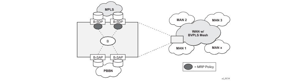
In a real life deployment, different customer VPNs do not share the same community of interest – for example, VPN instances may be located on different PBB PEs. The M:1 model depicted in Figure 96 requires a per VPN flood containment mechanism so that VPN traffic is distributed just to the B-VPLS locations that have customer VPN sites: for example, flooded traffic originated in the blue I-VPLS should be distributed just to the PBB PEs where blue I-VPLS instances are present – PBB PE B, E and F.
Per customer VPN distribution trees need to be created dynamically throughout the BVPLS as new customer I-VPLS instances are added in the PBB PEs.
Alcatel-Lucent’s PBB implementation employs the IEEE 802.1ak Multiple MAC Registration Protocol (MMRP) to dynamically build per I-VPLS distribution trees inside a certain B-VPLS infrastructure.
IEEE 802.1ak Multiple Registration Protocol (MRP) – Specifies changes to IEEE Std 802.1Q that provide a replacement for the GARP, GMRP and GVRP protocols. MMRP application of IEEE 802.1ak specifies the procedures that allow the registration/de-registration of MAC addresses over an Ethernet switched infrastructure.
In the PBB case, as I-VPLS instances are enabled in a certain PE, a group BMAC address is by default instantiated using the standard based PBB Group OUI and the ISID value associated with the I-VPLS.
When a new I-VPLS instance is configured in a PE, the IEEE 802.1ak MMRP application is automatically invoked to advertise the presence of the related group B-MAC on all active B-VPLS SAPs and SDP bindings.
When at least two I-VPLS instances with the same ISID value are present in a B-VPLS, an optimal distribution tree is built by MMRP in the related B-VPLS infrastructure as depicted in Figure 96.
 
Figure 96: Flood Containment Requirement in M:1 Model
 
MMRP Support Over B-VPLS SAPs and SDPs
MMRP is supported in B-VPLS instances over all the supported BVPLS SAPs and SDPs, including the primary and standby pseudowire scheme implemented for VPLS resiliency.
When a B-VPLS with MMRP enabled receives a packet destined to a specific group BMAC, it checks its own MFIB entries and if the group BMAC does not exist, it floods it everywhere. This should never happen as this kind of packet will be generated at the I-VPLS/PBB PE when a registration was received for a local I-VPLS group BMAC.
 
I-VPLS Changes and Related MMRP Behavior
This section describes the MMRP behavior for different changes in IVPLS.
1.
When an ISID is set for a certain I-VPLS and a link to a related B-VPLS is activated (for example, through the config>service>vpls>backbone-vpls vpls id:isid command), the group BMAC address is declared on all B-VPLS virtual ports (SAPs or SDPs).
2.
3.
4.
5.
 
Limiting the Number of MMRP Entries on a Per B-VPLS Basis
The MMRP exchanges create one entry per attribute (group BMAC) in the B-VPLS where MMRP protocol is running. When the first registration is received for an attribute, an MFIB entry is created for it.
Alcatel-Lucent’s implementation allows the user to control the number of MMRP attributes (group BMACs) created on a per B-VPLS basis. Control over the number of related MFIB entries in the B-VPLS FIB is inherited from previous releases through the use of the config>service>vpls>mfib-table-size table-size command. This ensures that no B-VPLS will take up all the resources from the total pool.
 
Optimization for Improved Convergence Time
Assuming that MMRP is used in a certain B-VPLS, under failure conditions the time it takes for the B-VPLS forwarding to resume may depend on the data plane and control plane convergence plus the time it takes for MMRP exchanges to settle down the flooding trees on a per ISID basis.
In order to minimize the convergence time, Alcatel-Lucent’s PBB implementation offers the selection of a mode where B-VPLS forwarding reverts for a short time to flooding so that MMRP has enough time to converge. This mode can be selected through configuration using the configure>service>vpl> bvpls>mrp>flood-time value command where value represents the amount of time in seconds that flooding will be enabled. Refer to the PBB Command Reference for command syntax and usage.
If this behavior is selected, the forwarding plane reverts to B-VPLS flooding for a configurable time period, for example, for a few seconds, then it reverts back to the MFIB entries installed by MMRP.
The following B-VPLS events initiate the switch from per I-VPLS (MMRP) MFIB entries to “B-VPLS flooding”:
 
Controlling MRP Scope using MRP Policies
MMRP advertises the Group BMACs associated with ISIDs throughout the whole BVPLS context regardless of whether a specific IVPLS is present in one or all the related PEs or BEBs. When evaluating the overall scalability the resource consumption in both the control and data plane must be considered:
In a multi-domain environment, for example multiple MANs interconnected through a WAN, the BVPLS and implicitly MMRP advertisement may span across domains. The MMRP attributes will be flooded throughout the BVPLS context indiscriminately, regardless of the distribution of IVPLS sites.
The solution described in this section limits the scope of MMRP control plane advertisements to a specific network domain using MRP Policy. ISID-based filters are also provided as a safety measure for BVPLS data plane.
Figure 97: Inter-Domain Topology
Figure 97 depicts the case of an Inter-domain deployment where multiple metro domains (MANs) are interconnected through a wide area network (WAN). A BVPLS is configured across these domains running PBB M:1 model to provide infrastructure for multiple IVPLS services. MMRP is enabled in the BVPLS to build per IVPLS flooding trees. In order to limit the load in the core PEs or PBB BCBs, the local IVPLS instances must use MMRP and data plane resources only in the MAN regions where they have sites. A solution to the above requirements is depicted in Figure 98. The case of native PBB metro domains inter-connected via a MPLS core is used in this example. Other technology combinations are possible.
Figure 98: Limiting the Scope of MMRP Advertisements
An MRP policy can be applied to the edge of MAN1 domain to restrict the MMRP advertisements for local ISIDs outside local domain. Or the MRP policy can specify the inter-domain ISIDs allowed to be advertised outside MAN1. The configuration of MRP policy is similar with the configuration of a filter. It can be specified as a template or exclusively for a specific endpoint under service mrp object. An ISID or a range of ISID(s) can be used to specify one or multiple match criteria that will be used to generate the list of Group MACs to be used as filters to control which MMRP attributes can be advertised. An example of a simple mrp-policy that allows the advertisement of Group BMACs associated with ISID range 100-150 is given below:
*A:ALA-7>config>service>mrp# info
----------------------------------------------
            mrp-policy "test" create
                default-action block
                entry 1 create
                    match
                        isid 100 to 150
                    exit 
        action allow
                exit
            exit
----------------------------------------------
A special action end-station is available under mrp-policy entry object to allow the emulation on a specific SAP/PW of an MMRP end-station. This is usually required when the operator does not want to activate MRP in the WAN domain for interoperability reasons or if it prefers to manually specify which ISID will be interconnected over the WAN. In this case the MRP transmission will be shutdown on that SAP/PW and the configured ISIDs will be used the same way as an IVPLS connection into the BVPLS, emulating a static entry in the related BVPLS MFIB. Also if MRP is active in the BVPLS context, MMRP will declare the related GBMAC(s) continuously over all the other BVPLS SAP/PW(s) until the mrp-policy end-station action is removed from the mrp-policy assigned to that BVPLS context.
The MMRP usage of the mrp-policy will ensure automatically that traffic using Group BMAC will not be flooded between domains. There could be though small transitory periods when traffic originated from PBB BEB with unicast BMAC destination may be flooded in the BVPLS context as unknown unicast in the BVPLS context for both IVPLS and PBB Epipe. To restrict distribution of this traffic for local PBB services a new ISID match criteria is added to existing mac-filters. The mac-filter configured with ISID match criterium can be applied to the same interconnect endpoint(s), BVPLS SAP or PW, as the mrp-policy to restrict the egress transmission any type of frames that contain a local ISID. An example of this new configuration option is described below:
----------------------------------------------
A;ALA-7>config>filter# info
----------------------------------------------
mac-filter 90 create
description "filter-wan-man"
type isid
scope template
entry 1 create
description "drop-local-isids"
match
isid from 100 to 1000
exit
action drop
exit
----------------------------------------------
These filters will be applied as required on a per B-SAP or B-PW basis just in the egress direction. The ISID match criteria is exclusive with any other criteria under mac-filter. A new mac-filter type attribute is defined to control the use of ISID match criteria and must be set to isid to allow the use of isid match criteria. The ISID tag is identified using the PBB ethertype provisioned under config>port>ethernet>pbb-etype.
 
 
PBB and BGP-AD
BGP auto-discovery is supported only in the BVPLS to automatically instantiate the BVPLS pseudowires and SDPs as described in the Layer 2 Service Guide.
 
PBB ELINE Service
ELINE service is defined in PBB (IEEE 802.1ah) as a point-to-point service over the B-component infrastructure. Alcatel-Lucent’s implementation offers support for PBB ELINE through the mapping of multiple Epipe services to a Backbone VPLS infrastructure.
The use of Epipe scales the ELINE services as no MAC switching, learning or replication is required in order to deliver the point-to-point service.
All packets ingressing the customer SAP/spoke-SDP are PBB encapsulated and unicasted through the B-VPLS “tunnel” using the backbone destination MAC of the remote PBB PE. Note that the Epipe service does not support the forwarding of PBB encapsulated frames received on SAPs or Spoke-SDPs through their associated B-VPLS service. PBB frames are identified based on the configured PBB Ethertype (0x88e7 by default).
All the packets ingressing the B-VPLS destined for the Epipe are PBB de-encapsulated and forwarded to the customer SAP/spoke-SDP.
A PBB ELINE service support the configuration of a SAP or non-redundant spoke-SDP.
 
Non-Redundant PBB Epipe Spoke Termination
This feature provides the capability to use non-redundant pseudowire connections on the access side of a PBB Epipe, where previously only SAPs could be configured.
 
PBB Using G.8031-Protected Ethernet Tunnels
IEEE 802.1ah Provider Backbone Bridging (PBB) specification employs provider MSTP (PMSTP) to ensure loop avoidance in a resilient native Ethernet core. The usage of P-MSTP means failover times depend largely on the size and the connectivity model used in the network. The use of MPLS tunnels provides a way to scale the core while offering fast failover times using MPLS FRR. There are still service provider environments where Ethernet services are deployed using native Ethernet backbones. A solution based on native Ethernet backbone is required to achieve the same fast failover times as in the MPLS FRR case.
The Alcatel-Lucent PBB implementation offers the capability to use core Ethernet tunnels compliant with ITU-T G.8031 specification to achieve 50 ms resiliency for backbone failures. This is required to comply with the stringent SLAs provided by service providers in the current competitive environment. The implementation also allows a LAG-emulating Ethernet Tunnel providing a complimentary native Ethernet ELAN capability. The LAG-emulating Ethernet tunnels and G.8031 protected Ethernet tunnels operate independently.
The next section describes an applicability example where an Ethernet service provider using native PBB offers a carrier of carrier backhaul service for mobile operators.
 
Solution Overview
A simplified topology example for a PBB network offering a carrier of carrier service for wireless service providers is depicted in Figure 99.
Figure 99: Mobile Backhaul Use Case
The wireless service provider in this example purchases an ELINE service between the ENNIs on PBB edge nodes, BEB1 and BEBn. PBB services are employing a type of Ethernet tunneling (Eth-tunnels) between BEBs where primary and backup member paths controlled by G.8031 1:1 protection are used to ensure faster backbone convergence. Ethernet CCMs based on IEEE 802.1ag specification may be used to monitor the liveliness for each individual member paths.
The Ethernet paths span a native Ethernet backbone where the BCBs are performing simple Ethernet switching between BEBs using an Epipe or a VPLS service.
Although the network diagram shows just the Epipe case, both PBB ELINE and ELAN services are supported.
 
Detailed Solution Description
This section discusses the details of the Ethernet tunneling for PBB. The main solution components are depicted in Figure 100.
Figure 100: PBB-Epipe with B-VPLS over Ethernet Tunnel
The PBB ELINE service is represented in the BEBs as a combination of an Epipe mapped to a BVPLS instance. A eth-tunnel object is used to group two possible paths defined by specifying a member port and a control tag. In our example, the blue-circle representing the eth-tunnel is associating in a protection group the two paths instantiated as (port, control-tag/bvid): a primary one of port 1/1/1, control-tag 100 and respectively a secondary one of port 2/2/2, control tag 200.
The BCBs devices will stitch each BVID between different BEB-BCB links using either a VPLS or Epipe service. Epipe instances are recommended as the preferred option due to increased tunnel scalability.
Fast failure detection on the primary and backup paths is provided using IEEE 802.1ag CCMs that can be configured to transmit at 10 msec interval. Alternatively, the link layer fault detection mechanisms like LoS/RDI or 802.3ah can be employed.
Path failover is controlled by an Ethernet protection module, based on standard G.8031 Ethernet Protection Switching. The Alcatel-Lucent implementation of Ethernet protection switching supports only the 1:1 model which is common practice for packet based services since it makes better use of available bandwidth. The following additional functions are provided by the protection module:
The secondary path requires a MEP to exchange the G.8031 APS PDUs. The following Ethernet CFM configuration in the eth-tunnel>path>eth-cfm>mep context can be used to enable the G.8031 protection without activating the Ethernet CCMs:
If a MEP is required for troubleshooting issues on the primary path, the configuration described above for the secondary path must be used to enable the use of Link Layer OAM on the primary path.
LAG loadsharing is offered to complement G.8031 protected Ethernet tunnels for situations where unprotected VLAN services are to be offered on some or all of the same native Ethernet links.
 
 
Figure 101: G.8031 P2P Tunnels and LAG-Like Loadsharing Co-Existence
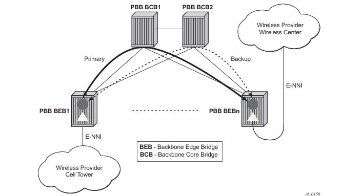
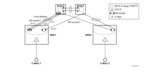
In Figure 101, the G.8031 Ethernet tunnels are used by the B-SAP(s) mapped to the green BVPLS entities supporting the ELINE services. A LAG-like loadsharing solution is provided for the Multipoint BVPLS (white circles) supporting the ELAN (IVPLS) services. The green G.8031 tunnels co-exist with LAG-emulating Ethernet tunnels (loadsharing mode) on both BEB-BCB and BCB-BCB physical links.
The G.8031-controlled Ethernet tunnels will select an active tunnel based on G.8031 APS operation, while emulated-LAG Ethernet tunnels will hash traffic within the configured links. Upon failure of one of the links the emulated-LAG tunnels will rehash traffic within the remaining links and fail the tunnel once the number of links breaches the minimum required (independent of G.8031-controlled Ethernet tunnels on the links shared emulated-LAG).
 
Detailed PBB Emulated LAG Solution Description
This section discusses the details of the emulated LAG Ethernet tunnels for PBB. The main solution components are depicted in Figure 102 which overlays Ethernet Tunnels services on the network from Figure 100.
 
Figure 102: Ethernet Tunnel Overlay
For a PBB Ethernet VLAN to make efficient use of an emulated LAG solution, a Management-VPLS (m-VPLS) is configured enabling Provider Multi-Instance Spanning Tree Protocol (P-MSTP). The m-VPLS is assigned to two SAPs; the eth-tunnels connecting BEB1 to BCB-E and BCB-F respectively reserving a range of VLANs for P-MSTP.
The PBB P-MSTP service is represented in the BEBs as a combination of an Epipe mapped to a BVPLS instance as before but now the PBB service is able to use the Ethernet tunnels under the P-MSTP control and load share traffic on the emulated LAN. In our example, the blue-circle representing the BVPLS is assigned to the SAPs which define two paths each. All paths are specified as primary precedence to load share the traffic.
A Management VPLS (m-VPLS) is first configured with a VLAN-range and assigned to the SAPs containing the path to the BCBs. The load shared eth-tunnel objects are defined by specifying a member ports and a control tag of zero. Then individual B-VPLS services can be assigned to the member paths of the emulated LAGs and defining the path encapsulation. Then individual services such as the IVPLS service can be assigned to the B-VPLS.
At the BCBs the tunnels are terminated the next BVPLS instance controlled by P-MSTP on the BCBs to forward the traffic.
In the event of link failure, the emulated LAG group will automatically adjust the number of paths. A threshold can be set whereby the LAG group is declared down. All emulated LAG operations are independent of any 8031-1to1 operation.
 
Support Service and Solution Combinations
The following considerations apply when Ethernet tunnels are configured under a VPLS service:
Eth-tunnels usage as a logical port in the config>redundancy>multi-chassis>peer>sync>port context
For further information, refer to the Services Overview Guide.
 
Periodic MAC Notification
Virtual BMAC learning frames (for example, the frames sent with the source MAC set to the virtual BMAC) can be sent periodically, allowing all BCBs/BEBs to keep the virtual BMAC in their Layer 2 forwarding database.
This periodic mechanism is useful in the following cases:
In each of the above cases, all of the remote BEB/BCBs will learn the virtual MAC in the worse case after the next learning frame is sent.
In addition, this will allow all of the above when to be used in conjunction with discard-unknown in the B-VPLS. Currently, if discard-unknown is enabled in all related B-VPLSes (to avoid any traffic flooding), all above cases could experience an increased traffic interruption, or a permanent loss of traffic, as only traffic towards the dual homed PBB-epipe can restart bi-directional communication. For example, it will reduce the traffic outage when:
The PBB-Epipe virtual MAC is flushed on a remote BEB/BCB due to the failover of an MC-LAG or A/S pseudowires within the customer’s access network, for example, in between the dual homed PBB-Epipe peers and their remote tunnel endpoint.
There is a failure in the PBB core causing the path between the two BEBs to pass through a different BCB.
It should be noted that this will not help in the case where the remote tunnel endpoint BEB fails. In this case traffic will be flooded when the remote BMAC ages out if discard-unknown is disabled. If discard-unknown is enabled, then the traffic will follow the path to the failed BEB but will eventually be dropped on the source BEB when the remote BMAC ages out on all systems.
In order to scale the implementation it is expected that the timescale for sending the periodic notification messages is much longer than that used for the current notification messages.
 
MAC Flush
 
PBB Resiliency for B-VPLS Over Pseudowire Infrastructure
The following VPLS resiliency mechanisms are also supported in PBB VPLS:
To support these resiliency options, extensive support for blackhole avoidance mechanisms is required.
 
Porting existing VPLS LDP MAC Flush in PBB VPLS
Both the I-VPLS and B-VPLS components inherit the LDP MAC flush capabilities of a regular VPLS to fast age the related FIB entries for each domain: CMACs for I-VPLS and BMACs for B-VPLS. Both types of LDP MAC flush are supported for I-VPLS and B-VPLS domains:
flush-all-but-mine - flush on positive event, for example:
flush-all-from-me - flush on negative event, for example:
In addition, only for the B-VPLS domain, changing the backbone source MAC of a B-VPLS will trigger a LDP MAC flush-all-from-me to be sent in the related active topology. At the receiving PBB PE, a BMAC flush automatically triggers a flushing of the CMACs associated with the old source BMAC of the B-VPLS.
 
PBB Blackholing Issue
In the PBB VPLS solution, a B-VPLS may be used as infrastructure for one or more I-VPLS instances. B-VPLS control plane (LDP Signaling or P-MSTP) replaces I-VPLS control plane throughout the core. This is raising an additional challenge related to blackhole avoidance in the I-VPLS domain as described in this section.
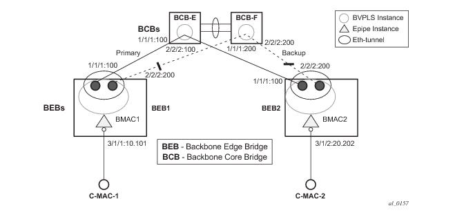
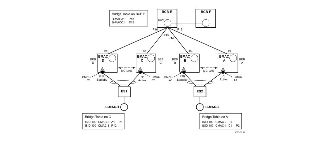
PBB Blackholing Issue — Assuming that the link between PE A1 and node 5 is active, the remote PEs participating in the orange VPN (for example, PE D) will learn the CMAC X associated with backbone MAC A1. Under failure of the link between node 5 and PE A1 and activation of link to PE A2, the remote PEs (for example, PE D) will black-hole the traffic destined for customer MAC X to BMAC A1 until the aging timer expires or a packet flows from X to Y through the PE A2. This may take a long time (default aging timer is 5 minutes) and may affect a large number of flows across multiple I-VPLSes.
A similar issue will occur in the case where node 5 is connected to A1 and A2 I-VPLS using active/standby pseudowires. For example, when node 5 changes the active pseudowire, the remote PBB PE will keep sending to the old PBB PE.
Another case is when the QinQ access network dual-homed to a PBB PE uses RSTP or MVPLS with MSTP to provide loop avoidance at the interconnection between the PBB PEs and the QinQ SWs. In the case where the access topology changes, a TCN event will be generated and propagated throughout the access network. Similarly, this change needs to be propagated to the remote PBB PEs to avoid blackholing.
A solution is required to propagate the I-VPLS events through the backbone infrastructure (B-VPLS) in order to flush the customer MAC to BMAC entries in the remote PBB. As there are no IVPLS control plane exchanges across the PBB backbone, extensions to B-VPLS control plane are required to propagate the I-VPLS MAC flush events across the B-VPLS.
 
LDP MAC Flush Solution for PBB Blackholing
In the case of an MPLS core, B-VPLS uses T-LDP signaling to set up the pseudowire forwarding. The following I-VPLS events must be propagated across the core B-VPLS using LDP MAC flush-all-but-mine or flush-all-from-me indications:
For flush-all-but-mine indication (“positive flush”):
For flush-all-from-me indication (“negative flush”)
In order to propagate the MAC flush indications triggered by the above events, the PE that originates the LDP MAC withdraw message must be identified. In regular VPLS “mine”/”me” is represented by the pseudowire associated with the FEC and the T-LDP session on which the LDP MAC withdraw was received. In PBB, this is achieved using the B-VPLS over which the signaling was propagated and the BMAC address of the originator PE.
Alcatel-Lucent PBB-VPLS solution addresses this requirement by inserting in the BVPLS LDP MAC withdraw message a new PBB-TLV (type-length-value) element. The new PBB TLV contains the source BMAC identifying the originator (“mine”/”me”) of the flush indication and the ISID list identifying the I-VPLS instances affected by the flush indication.
There are a number of advantages to this approach. Firstly, the PBB-TLV presence indicates this is a PBB MAC Flush. As a result, all PEs containing only the B-VPLS instance will automatically propagate the LDP MAC withdraw in the B-VPLS context respecting the split-horizon and active link topology. There is no flushing of the B-VPLS FIBs throughout the core PEs. Subsequently, the receiving PBB VPLS PEs uses the BMAC and ISID list information to identify the specific I-VPLS FIBs and the CMAC entries pointing to the source BMAC included in the PBB TLV.
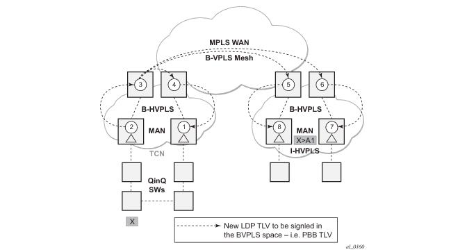
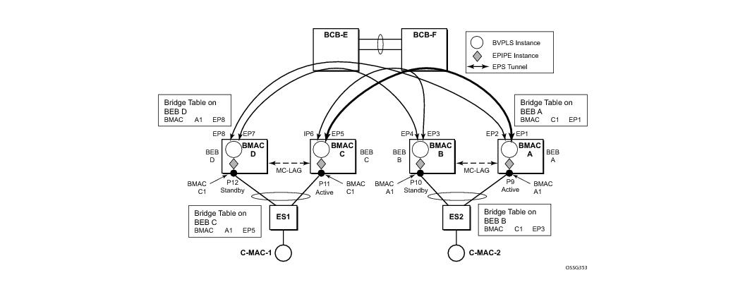
An example of processing steps involved in PBB MAC Flush is depicted in Figure 103 for the case when a Topology Change Notification (TCN) is received on PBB PE 2 from a QinQ access in the I-VPLS domain.
Figure 103: TCN Triggered PBB Flush-ALl-But-Mine Procedure
The received TCN may be related to one or more I-VPLS domains. This will generate a MAC Flush in the local I-VPLS instance(s) and if configured, it will originate a PBB MAC flush-all-but-mine throughout the related B-VPLS context(s) represented by the white circles 1-8 in our example.
A PBB-TLV is added by PE2 to the regular LDP MAC flush-all-but-mine. BMAC2, the source BMAC associated with B-VPLS on PE2 is carried inside the PBB TLV to indicate who “mine” is. The ISID list identifying the I-VPLS affected by the TCN is also included if the number of affected I-VPLS is 100 or less. No ISID list is included in the PBB-TLV if more than 100 ISIDs are affected. If no ISID list is included, then the receiving PBB PE will flush all the local I-VPLS instances associated with the B-VPLS context identified by the FEC TLV in the LDP MAC withdraw message. This is done to speed up delivery and processing of the message.
Recognizing the PBB MAC flush, the B-VPLS only PEs 3, 4, 5 and 6 refrain from flushing their B-VPLS FIB tables and propagate the MAC flush message regardless of their “propagate-mac-flush” setting.
When LDP MAC withdraw reaches the terminating PBB PEs 1 and 7, the PBB-TLV information is used to flush from the I-VPLS FIBs all CMAC entries except those associated with the originating BMAC BM2. If specific I-VPLS ISIDs are indicated in the PBB TLV, then the PBB PEs will flush only the CMAC entries from the specified I-VPLS except those mapped to the originating BMAC. Flush-all-but-mine indication is not propagated further in the I-VPLS context to avoid information loops.
The other events that trigger Flush-all-but-mine propagation in the B-VPLS (pseudowire/SDP binding activation, Reception of an LDP MAC Withdraw) are handled similarly. The generation of PBB MAC flush-all-but-mine in the B-VPLS must be activated explicitly on a per I-VPLS basis with the command send-bvpls-flush all-but-mine. The generation of PBB MAC flush-all-from-me in the B-VPLS must be activated explicitly on a per I-VPLS basis with the command send-bvpls-flush all-from-me.
 
Access Multi-Homing for Native PBB (B-VPLS over SAP Infrastructure)
Alcatel-Lucent PBB implementation allows the operator to use a native Ethernet infrastructure as the PBB core. Native Ethernet tunneling can be emulated using Ethernet SAPs to interconnect the related B-VPLS instances. This kind of solution might fit certain operational environments where Ethernet services was provided in the past using QinQ solution. The drawback is that no LDP signaling is available to provide support for Access Multi-homing for Epipe (pseudowire Active/Standby status) or I-VPLS services (LDP MAC Withdraw). An alternate solution is required.
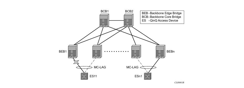
A PBB network using Native Ethernet core is depicted in Figure 104. MC-LAG is used to multi-home a number of edge switches running QinQ to PBB BEBs.
Figure 104: Access Dual-Homing into PBB BEBs - Topology View
The interrupted line from the MC-LAG represents the standby, inactive link; the solid line is the active link. The BEBs are dual-homed to two core switches BCB1 and BCB2 using native Ethernet SAPs on the B-VPLS side. Multi-point B-VPLS with MSTP for loop avoidance can be used as the PBB core tunneling. Alternatively point-to-point, G.8031 protected Ethernet tunnels can be also used to interconnect B-VPLS instances in the BEBs as described in the PBB over G.8031 protected Ethernet tunnels.
Alcatel-Lucent implementation provides a solution for both PBB ELINE (Epipe) and ELAN (IVPLS) services that avoids PBB blackholing when the active ES11-BEB1 link fails. It also provides a consistent behavior for both service type and for different backbone types: for example, native Ethernet, MPLS, or a combination. Only MC-LAG is supported initially as the Access-Multi-homing mechanism.
 
Solution Description for I-VPLS Over Native PBB Core
The use case described in the previous section is addressed by enhancing the existing native PBB solution to provide for blackhole avoidance.
The topology depicted in Figure 105 describes the details of the solution for the I-VPLS use case. Although the native PBB use case is used, the solution works the same for any other PBB infrastructure: for example, G.8031 Ethernet tunnels, pseudowire/MPLS, or a combination.
Figure 105: PBB Active Topology and Access Multi-Homing
ES1 and ES2 are dual-homed using MC-LAG into two BEB devices: ES1 to BEB C and BEB D, ES2 to BEB A and BEB B. MC-LAG P11 on BEB C and P9 on BEB A are active on each side.
In the service context, the triangles are I-VPLS instances while the small circles are B-VPLS components with the related, per BVPLS source BMACs indicated next to each BVPLS instances. P-MSTP or RSTP may be used for loop avoidance in the multi-point BVPLS. For simplicity, only the active SAPs (BEB P2, P4, P6 and P8) are shown in the diagram.
In addition to the source BMAC associated with each BVPLS, there is an additional BMAC associated with each MC-LAG supporting multi-homed I-VPLS SAPs. The BEBs that are in a multi-homed MC-LAG configuration share a common B-MAC on the related MC-LAG interfaces. For example, a common BMAC C1 is associated in this example with ports P11 and P12 participating in the MC-LAG between BEB C and BEB D while BMAC A1 is associated with ports P9 and P10 in the MC-LAG between BEB A and BEB B. While BMAC C1 is associated through the I-VPLS SAPs with both BVPLS instances in BEB C and BEB D, it is actively used for forwarding to I-VPLS SAPs only on BEB C containing the active link P11.
MC-LAG protocol keeps track of which side (port or LAG) is active and which is standby for a given MC-LAG grouping and activates the standby in case the active one fails. The source BMAC C1 and A1 are used for PBB encapsulation as traffic arrives at the IVPLS SAPs on P11 and P9 respectively. MAC Learning in the BVPLS instances installs MAC FIB entries in BCB-E and BEB A as depicted in Figure 105.
Active link (P11) or access node (BEB C) failures are activating through MC-LAG protocol the standby link (P12) participating in the MC-LAG on the pair MC-LAG device (BEB D).
Figure 106 depicts the case of access link failure.
Figure 106: Access Multi-Homing - Link Failure
On failure of the active link P11 on BEB C the following processing steps apply:
Identical procedure is used when the whole BEB C fails.
 
Solution Description for PBB Epipe over G.8031 Ethernet Tunnels
This section discusses the Access Multi-Homing solution for PBB ELINE over an infrastructure of G.8031 Ethernet tunnels. Although a specific use case is used, the solution works the same for any other PBB infrastructure: for example, native PBB, pseudowire/MPLS, or a combination.
The PBB ELINE service and the related BVPLS infrastructure are depicted in Figure 107.
Figure 107: Access Multi-Homing Solution for PBB Epipe
The ELINE instances are connected through the B-VPLS infrastructure. Each B-VPLS is interconnected to the BEBs in the remote pair using the G.8031, Ethernet Protection Switched (EPS) tunnels. Only the active Ethernet paths are shown in the network diagram to simplify the explanation. Split Horizon Groups may be used on EPS tunnels to avoid running MSTP/RSTP in the PBB core.
The same BMAC addressing scheme is used as in the ELAN case: a BMAC per B-VPLS and additional BMACs associated with each MC-LAG connected to an Epipe SAP. The BMACs associated with the active MC-LAG are actively used for forwarding into B-VPLS the traffic ingressing related Epipe SAPs.
MC-LAG protocol keeps track of which side is active and which is standby for a given MC-LAG grouping and activates the standby link in a failure scenario. The source BMACs C1 and A1 are used for PBB encapsulation as traffic arrives at the Epipe SAPs on P11 and P9, respectively. MAC Learning in the B-VPLS instances installs MAC FIB entries in BEB C and BEB A as depicted in Figure 107. The highlighted Ethernet tunnel (EPS) will be used to forward the traffic between BEB A and BEB C.
Active link (P11) or access node (BEB C) failures are activating through MC-LAG protocol, the standby link (P12) participating in the MC-LAG on the pair MC-LAG device (BEB D). The failure of BEB C is depicted in Figure 108. The same procedure applies for the link failure case.
Figure 108: Access Dual-Homing for PBB ELINE - BEB Failure
The following process steps apply:
Note that the same process is executed for all the MC-LAGs affected by BEB C failure so BEB failure will be the worst case scenario.
 
Dual-Homing into PBB Epipe - Local Switching Use Case
When the service SAPs were mapped to MC-LAGs belonging to the same pair of BEBs in earlier releases, an IVPLS had to be configured even if there were just two SAPs active at any point in time. Since then, the PBB Epipe model has been enhanced to support configuring in the same Epipe instance two SAPs and a BVPLS uplink as depicted in Figure 109.
Figure 109: Solution for Access Dual-Homing with Local Switching for PBB Eline/Epipe
The PBB Epipe represented by the yellow diamond on BEB1 points through the BVPLS uplink to the BMAC associated with BEB2. The destination BMAC can be either the address associated with the green BVPLS on BEB2 or the BMAC of the SAP associated with the pair MC-LAG on BEB2 (preferred option).
The Epipe information model is expanded to accommodate the configuration of two SAPs (I-SAPs) and of a BVPLS uplink in the same time. For this configuration to work in an Epipe environment, only two of them will be active in the forwarding plane at any point in time, specifically:
 
BGP Multi-homing for I-VPLS
This section describes the application of BGP multi-homing to I-VPLS services. BGP multi-homing for I-VPLS uses the same mechanisms as those used when BGP multi-homing is configured in a non-PBB VPLS service, which are described in detail in the Layer 2 Services Guide.
The multi-homed sites can be configured with either a SAP or spoke-SDP, and support both split-horizon groups and fate-sharing by the use of oper-groups.
When the B-VPLS service is using LDP signaled pseudowires, blackhole protection is supported after a multi-homing failover event when send-flush-on-failure and send-bvpls-flush flush-all-from-me is configured within the I-VPLS. This causes the system on which the site object fails to send a MAC flush all-from-me message so that customer MACs are flushed on the remote backbone edge bridges using a flush-all-from-me message. The message sent includes a PBB TLV which contains the source BMAC identifying the originator (“mine”/“me”) of the flush indication and the ISID list identifying the I-VPLS instances affected by the flush indication, see section LDP MAC Flush Solution for PBB Blackholing .
The VPLS preference sent in BGP multi-homing updates will be always be set to zero, however, if a non-zero value is received in a valid BGP multi-homing update it will be used to influence the designated forwarder (DF) election.
 
Access Multi-Homing over MPLS for PBB Epipes
It is possible to connect backbone edge bridges (BEBs) configured with PBB Epipes to an edge device using active/standby pseudowires over an MPLS network. This is shown in Figure 110.
Figure 110: Active/Standby PW into PBB Epipes
In this topology, the edge device (CE1) is configured with multiple Epipes to provide virtual lease line (VLL) connectivity across a PBB network. CE1 uses active/standby pseudowires (PWs) which terminate in PBB Epipe services on BEB1 and BEB2 and are signaled accordingly using the appropriate pseudowire status bits.
Traffic is sent from CE1 on the active pseudowires into the PBB epipe services, then onto the remote devices through the B-VPLS service. It is important that traffic sent to CE1 is directed to the BEB that is attached to the active pseudowire connected to CE1. To achieve this, a virtual backbone MAC (vBMAC) is associated with the services on CE1.
The vBMAC is announced into the PBB core by the BEB connected to the active pseudowire using SPBM configured in the B-VPLS services; hence SPBM is mandatory. In Figure 110, the vBMAC would be announced by BEB1; if the pseudowires failed over to BEB2, BEB1 would stop announcing the vBMAC and BEB2 will start announcing it.
The remote services are configured to use the vBMAC as the backbone destination MAC (backbone-dest-mac) which results in traffic being sent to the desired BEB.
The vBMAC is configured under the SDP used to connect to the edge device’s active/standby pseudowires using the command source-bmac-lsb. This command defines a sixteen (16) bit value which overrides the sixteen least-significant-bits of source backbone MAC (source-bmac) to create the vBMAC. The operator must ensure that the vBMACs match on the two peering BEBs for a corresponding SDP.
The PBB Epipe pseudowires are identified to be connected to an edge device active/standby pseudowire using the spoke-sdp parameter use-sdp-bmac. Enabling this parameter will cause traffic forwarded from this spoke-SDP into the B-VPLS domain to use the vBMAC as its source MAC address when both this, and the control pseudowire, are in the active state on this BEB.
Note that PBB Epipe pseudowires connected to edge device’s non-active/standby pseudowires are still able to use the same SDP.
To cater for the case where there are multiple edge device active/standby pseudowires using a given SDP, one pseudowire must be identified to be the control pseudowire (using the source-bmac-lsb parameter control-pw-vc-id). The state of the control pseudowire determines the announcing of the vBMAC by SPBM into the B-VPLS based on the following conditions:
It is expected that pseudowires configured using an SDP with source-bmac-lsb and with the parameter use-sdp-bmac are in the same state (up, down, active, standby) as the control pseudowire. If this is not the case, the following scenarios are possible (based on Figure 110):
Alarms are raised to track if, on the BEB with the control pseudowire in the standby/down state, any non-control pseudowires go active. Specifically, there will be an alarm when the first non-control pseudowire becomes active and another alarm when the last non-control pseudowire becomes standby/down.
If both control pseudowires are active (neither in standby) then both BEBs would announce the vBMAC – this would happen if the edge device was a 7x50 using an Epipe service without standby-signaling-master configured. Traffic from remote BEBs on any service related to the vBMAC would be sent to the nearest SPBM BEB and it would depend on the state of the pseudowires on each BEB as to whether it could reach the edge device. Similarly, the operator must ensure that the corresponding service pseudowires on each BEB are configured as the control pseudowire, otherwise SPBM might advertise the vBMAC from both BEBs resulting in the same consequences.
All traffic received from the edge device on a pseudowire into a PBB Epipe, on the BEB with the active control pseudowire, is forwarded by the B-VPLS using the vBMAC as the source backbone MAC, otherwise the source-bmac is used.
The control pseudowire can be changed dynamically without shutting down the spoke SDPs, SDP or withdrawing the SPBM advertisement of the vBMAC; this allows a graceful change of the control pseudowire. Clearly, any change should be performed on both BEBs as closely in time as possible to avoid an asymmetric configuration, ensuring that the new control pseudowire is in the same state as the current control pseudowire on both BEBs during the change.
The following are not supported:
 
PBB and IGMP/MLD Snooping
The IGMP/MLD snooping feature provided for VPLS is supported similarly in the PBB I‑VPLS context, in order to provide efficient multicast replication in the customer domain. The difference from regular VPLS is the handling of IGMP/MLD messages arriving from the B‑VPLS side over a B‑VPLS SAP or SDP.
The first IGMP/MLD join message received over the local B-VPLS adds all the B‑VPLS SAP and SDP components into the related multicast table associated with the I‑VPLS context. This is in line with the PBB model, where the B‑VPLS infrastructure emulates a backbone LAN to which every I‑VPLS is connected by one virtual link.
When the querier is connected to a remote I‑VPLS instance, over the B-VPLS infrastructure, its location is identified by the B‑VPLS SDP and SAP on which the query was received. It is also identified by the source BMAC address used in the PBB header for the query message. This is the BMAC associated with the B‑VPLS instance on the remote PBB PE.
It is also possible to configure that a multicast router exists in a remote I‑VPLS service. This can be achieved using the mrouter-dest CLI command to specify the mac-name of the destination BMAC to be used to reach the remote I‑VPLS service. This command is available in the VPLS service PBB IGMP and MLD snooping contexts.
The following are not supported in a PBB I-VPLS context with IGMP snooping or MLD snooping:
The following are not supported in a PBB I-VPLS context with MLD snooping:
 
 
PBB QoS
For PBB encapsulation, the configuration used for DE and dot1p in SAP and SDP policies applies to the related bits in both backbone dot1q (BTAG) and ITAG fields.
The following QoS processing rules apply for PBB B-VPLS SAPs and SDPs:
B-VPLS SAP ingress
B-VPLS SAP egress
B-VPLS SDP (network) ingress policy
B-VPLS SDP (network) egress policy
 
Transparency of Customer QoS Indication through PBB Backbone
Similar to PW transport, operators want to allow their customers to preserve all eight Ethernet COS markings (three dot1p bits) and the discard eligibility indication (DE bit) while transiting through a PBB backbone.
This means any customer COS marking on the packets inbound to the ingress SAP must be preserved when going out on the egress SAP at the remote PBB PE even if the customer VLAN tag is used for SAP identification at the ingress.
A solution to the above requirements is depicted in Figure 111.
Figure 111: PCP, DE Bits Transparency in PBB
The PBB BVPLS is represented by the blue pipe in the middle with its associated COS represented through both the service (I-tag) and tunnel COS (BVID dot1p+DE or PW EXP bits).
The customer COS is contained in the orange dot1q VLAN tags managed in the customer domains. There may be one (CVID) or two (CVID, SVID) tags used to provide service classification at the SAP. IVPLS or PBB Epipe instances (orange triangles) are used to provide a Carrier-of-Carrier service.
As the VLAN tags are stripped at the ingress SAP and added back at the egress SAP, the PBB implementation must provide a way to maintain the customer QoS marking. This is done using a force-qtag-forwarding configuration on a per IVPLS/Epipe basis under the node specifying the uplink to the related BVPLS. When force-qtag-forwarding is enabled, a new VLAN tag is added right after the CMAC addresses using the configured QTAG. The dot1p, DE bits from the specified outer/inner customer QTAG will be copied in the newly added tag.
Once the force-qtag-forwarding is enabled in one IVPLS/PBB Epipe instance, it will be enabled in all of the related instances.
At the remote PBB PE/BEB on the egress SAPs or SDPs, the first QTAG after the CMAC addresses will be removed and its dot1p, DE bits will be copied in the newly added customer QTAGs.
 
Configuration Examples
This section gives usage examples for the new commands under PBB Epipe or IVPLS instances.
PBB IVPLS usage:
configure service vpls 100 ivpls
sap 1/1/1:101
pbb
backbone-vpls 10 isid 100
force-qtag-forwarding
 
PBB Epipe Usage:
configure service epipe 200
sap 1/1/1:201
pbb
tunnel 10 backbone-dest-mac ab-bc-cd-ef-01-01 isid 200
force-qtag-forwarding
 
Details Solution Description
Figure 111 depicts a specific use case. Keeping the same topology - an ingress PBB PE, a PBB core and an egress PBB PE - let us consider the generic use case where:
1.
2.
3.
Similar to the Ethernet-VLAN VC Type, the following packet processing steps apply for different scenarios.
Ingress PE, ingress I-SAP case with force-qtag-forwarding enabled under PBB Epipe or IVPLS
The QTAG is inserted automatically right after CMAC addresses; an ethertype value of 8100 is used.
Case 1: SAP type = null/dot1q default (1/1/1 or 1/1/1.*) so there is no service delimiting tag used and stripped on the ingress side.
Case 2: SAP type = dot1q or qinq default (1/1/1.100 or 1/1/1.100.*) so there is a service delimiting tag used and stripped.
Case 3: SAP type = qinq (1/1/1.100.10) so there are two service delimiting tags used and stripped.
Ingress PE, ingress I-SDP/PW case with force-qtag-forwarding enabled under PBB Epipe or IVPLS
The QTAG is inserted automatically right after CMAC addresses; an ethertype value of 8100 is used.
Case 1: SDP vc-type = Ethernet (force-vlan-vc-forwarding= not supported for I-PW) so there is no service delimiting tag stripped on the ingress side.
Case 2: SDP vc-type = Ethernet VLAN so there is a service delimiting tag stripped.
PBB packets are tunneled through the core the same way for native ETH/MPLS cases.
Egress PE, egress I-SAP case with force-qtag-forwarding enabled under PBB Epipe or VPLS
Case 1: SAP type = null/dot1q default (2/2/2 or 2/2/2.*) so there is no service delimiting tag added on the egress side.
Case 2: SAP type = dot1q/qinq default (3/1/1.300 or 3/1/1.300.*) so a service delimiting tag is added on egress
Case 3: SAP type = qinq (3//1/1.300.30) so two service delimiting tags are added on egress
If the qinq-mark-top-only command under vpls>sap>egress is not enabled (default), the policy is applied to both service delimiting tags.
Egress PE, egress I-SDP case with force-qtag-forwarding enabled under PBB Epipe or IVPLS
Case 1: I-SDP vc-type = Ethernet VLAN so there is service delimiting tag added after PW encapsulation.
Case 2: I-SDP vc-type = Ethernet (force-vlan-vc-forwarding=not supported for I-SDPs) so there is no service delimiting tag added on egress PW
 
Egress B-SAP per ISID Shaping
This feature allows users to perform egress data path shaping of packets forwarded within a B-VPLS SAP. The shaping is performed within a more granular context within the SAP. The context for a B-SAP is an ISID.
Note: This feature is supported on IOM-3 and IMM on the 7750 SR‑7, 7750 SR‑12, 7750-C12, and 7750-C4. This feature is not supported on 7450 ESS‑1 or 7750 SR‑1.
 
B-SAP Egress ISID Shaping Configuration
Users can enable the per-ISID shaping on the egress context of a B-VPLS SAP by configuring an encapsulation group, referred to as encap-group in CLI, under the QoS sub-context, referred to as encap-defined-qos.
config>service>vpls>sap>egress>encap-defined-qos>encap-group group-name [type group-type] [qos-per-member] [create]
The group name is unique across all member types. The isid type is currently the only option.
The user adds or removes members to the encap-group, one at a time or as a range of contiguous values. However, when the qos-per-member option is enabled, members must be added or removed one at a time. These members are also referred to as ISID contexts.
config>service> vpls>sap>egress>encap-defined-qos>encap-group
[no] member encap-id [to encap-id]
The user can configure one or more encap-groups in the egress context of the same B-SAP, defining different ISID values and applying each a different SAP egress QoS policy, and optionally a different scheduler policy/agg-rate-limit. Note that ISID values are unique within the context of a B-SAP. The same ISID value cannot be re-used in another encap-group under the same B-SAP but can be re-used in an encap-group under a different B-SAP. Finally, if the user adds to an encap-group an ISID value which is already a member of this encap-group, the command causes no effect. The same if the user attempts to remove an ISID value which is not a member of this encap-group.
Once a group is created, the user assigns a SAP egress QoS policy, and optionally a scheduler policy or aggregate rate limit, using the following commands:
config>service> vpls>sap>egress>encap-defined-qos>encap-group>qos sap-egress-policy-id
config>service> vpls>sap>egress>encap-defined-qos>encap-group>scheduler-policy scheduler-policy-name
config>service> vpls>sap>egress>encap-defined-qos>encap-group>agg-rate-limit kilobits-per-second
Note that a SAP egress QoS policy must first be assigned to the created encap-group before the user can add members to this group. Conversely, the user cannot perform the no qos command until all members are deleted from the encap-group.
An explicit or the default SAP egress QoS policy will continue to be applied to the entire B-SAP but this will serve to create the set of egress queues which will be used to store and forward a packet which does not match any of the defined ISID values in any of the encap-groups for this SAP.
Only the queue definition and fc-to-queue mapping from the encap-group SAP egress QoS policy is applied to the ISID members. All other parameters configurable in a SAP egress QoS policy must be inherited from egress QoS policy applied to the B-SAP.
Furthermore, any other CLI option configured in the egress context of the B-SAP will continue to apply to packets matching a member of any encap-group defined in this B-SAP.
Note also that the SAP egress QoS policy must not contain an active policer or an active queue-group queue or the application of the policy to the encap-group will be failed. A policer or a queue-group queue is referred to as active if one or more FC map to it in the QoS policy or the policer is referenced within the action statement of an IP or IPv6 criteria statement. Conversely, the user will not be allowed to assign a FC to a policer or a queue-group queue, or reference a policer within the action statement of an IP or IPv6 criteria statement, once the QoS policy is applied to an encap-group.
The qos-per-member keyword allows the user to specify that a separate queue set instance and scheduler/agg-rate-limit instance will be created for each ISID value in the encap-group. By default, shared instances will be created for the entire encap-group.
Note that when the B-SAP is configured on a LAG port, the ISID queue instances defined by all the encap-groups applied to the egress context of the SAP will be replicated on each member link of the LAG. The set of scheduler/agg-rate-limit instances will be replicated per link or per IOM depending if the adapt-qos option is set to link/port-fair mode or distribute mode. This is the same behavior as that applied to the entire B-SAP in the current implementation.
 
Provisioning Model
The main objective of this proposed provisioning model is to separate the definition of the QoS attributes from the definition of the membership of an encap-group. The user can apply the same SAP egress QoS policy to a large number of ISID members without having to configure the QoS attributes for each member.
The following are conditions of the provisioning model:
A SAP egress policy ID must be assigned to an encap-group before any member can be added regardless of the setting of the qos-per-member option.
When qos-per-member is specified in the encap-group creation, the user must add or remove ISID members one at a time. The command is failed if a range is entered.
When qos-per-member is specified in the encap-group creation, the sap-egress QoS policy ID and the scheduler policy name cannot be changed unless the group membership is empty. However, the agg-rate-limit parameter value can be changed or the command removed (no agg-rate-limit).
When qos-per-member is not specified in the encap-group creation, the user may add or remove ISID members as a singleton or as a range of contiguous values.
When qos-per-member is not specified in the encap-group creation, the sap-egress QoS policy ID and the scheduler policy name or agg-rate-limit parameter value may be changed at anytime. Note however that the user cannot still remove the SAP egress QoS policy (no qos) while there are members defined in the encap-group.
Operationally, the provisioning consists of the following steps:
1.
2.
3.
Manage membership for the encap-group using the member command (or SNMP equivalent).
-
The member command is all-or-nothing. No ISID in a range is added if one fails
-
-
4.
Logically, the encap-group membership operation can be viewed as three distinct functions:
1.
2.
3.
 
Egress Queue Scheduling
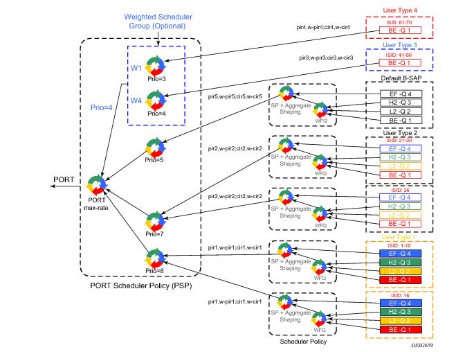
Figure 112 displays an example of egress queue scheduling.
Figure 112: Egress Queue Scheduling
The queuing and scheduling re-uses existing scheduler policies and port scheduler policy with the difference that a separate set of FC queues are created for each defined ISID context according to the encap-group configured under the egress context of the B-SAP. This is in addition to the set of queues defined in the SAP egress QoS policy applied to the egress of the entire SAP.
The user type in Figure 112 maps to a specific encap-group defined for the B-SAP in CLI. The operator has the flexibility of scheduling many user types by assigning different scheduling parameters as follows:
A second tier scheduler can be used as a WFQ scheduler to aggregate a subset of the ISID context FC queues. Alternatively, the operator can apply an aggregate rate limit to the ISID context instead of a scheduler policy.
In order to make the shaping of the ISID context reflect the SLA associated with each user type, it is required to subtract the operator’s PBB overhead from the Ethernet frame size. For that purpose, a packet byte-offset parameter is added to the context of a queue.
config>qos>sap-egress>queue>packet-byte-offset {add bytes | subtract bytes}
When a packet-byte-offset value is applied to a queue instance, it adjusts the immediate packet size. This means that the queue rates, like the operational PIR and CIR, and queue bucket updates use the adjusted packet size. In addition, the queue statistics will also reflect the adjusted packet size. Scheduler policy rates, which are data rates, will use the adjusted packet size.
The port scheduler max-rate and priority level rates and weights, if a Weighted Scheduler Group is used, are always “on-the-wire” rates and thus use the actual frame size. The same applies to the agg-rate-limit on a SAP, a subscriber, or a Multi-Service Site (MSS) when the queue is port-parented.
When the user enables frame-based-accounting in a scheduler policy or queue-frame-based-accounting with agg-rate-limit in a port scheduler policy, the queue rate is capped to a user- configured “on-the-wire” rate but the packet-byte-offset value is still in effect as explained above.
 
B-SAP per-ISID Shaping Configuration Example
The following CLI configuration for B-SAP per-ISID shaping achieves the specific use case shown in Figure 112.
config
 qos
       port-scheduler-policy "bvpls-backbone-port-scheduler"
       group scheduler-group1 create
       rate 1000
       level 3 rate 1000 group scheduler-group1 weight w1
       level 4 rate 1000 group scheduler-group1 weight w4
       level 5 rate 1000 cir-rate 100
       level 7 rate 5000 cir-rate 5000
       level 8 rate 500 cir-rate 500
exit
 
       scheduler-policy "user-type1"
       tier 1
       scheduler root
port-parent level 8 rate pir1 weight w-pir1 cir-level 8 cir-rate cir1 cir-weight w-cir1
			exit
       tier 3
       scheduler wfq
       	rate pir1
       parent root
			exit
		exit
exit
 
       scheduler-policy "user-type2"
       tier 1
       scheduler root
port-parent level 7 rate pir2 weight w-pir2 cir-level 7 cir-rate cir2 cir-weight w-cir2
			exit
       tier 3
       scheduler wfq
       	rate pir2
       parent root
			exit
		exit
exit
 
       scheduler-policy "b-sap"
       tier 1
       scheduler root
port-parent level 5 rate pir5 weight w-pir5 cir-level 1 cir-rate cir5 cir-weight w-cir5
			exit
       tier 3
       scheduler wfq
       	rate pir5
       parent root
			exit
		exit
exit
 
	sap-egress 100 // user type 1 QoS policy
	queue 1
            	parent wfq weight x level 3 cir-weight x cir-level 3
			packet-byte-offset subtract bytes 22
 queue 2
			packet-byte-offset subtract bytes 22
            	parent wfq weight y level 3 cir-weight y cir-level 3
 queue 3
			packet-byte-offset subtract bytes 22
            	parent wfq weight z level 3 cir-weight z cir-level 3
 queue 4 
            	parent root level 8 cir-level 8
			packet-byte-offset subtract bytes 22
 fc be queue 1
 fc l2 queue 2 
 fc h2 queue 3 
 fc ef queue 4 
exit
	 
       sap-egress 200 // user type 2 QoS policy
 queue 1 
            	parent wfq weight x level 3 cir-weight x cir-level 3
			packet-byte-offset subtract bytes 26
 queue 2
            	parent wfq weight y level 3 cir-weight y cir-level 3
			packet-byte-offset subtract bytes 26
queue 3
            	parent wfq weight z level 3 cir-weight z cir-level 3
			packet-byte-offset subtract bytes 26
queue 4
            	parent root level 8 cir-level 8
			packet-byte-offset subtract bytes 26
 fc be queue 1
 fc l2 queue 2 
 fc h2 queue 3 
 fc ef queue 4 
exit
 
       sap-egress 300 // User type 3 QoS policy
 queue 1
            	port-parent level 4 rate pir3 weight w-pir3 cir-level  
       4 cir-rate cir3 cir-weight w-cir3
			packet-byte-offset subtract bytes 22
 fc be queue 1
exit
 
       sap-egress 400 // User type 4 QoS policy
 queue 1 
            	port-parent level 3 rate pir4 weight w-pir4 cir-level  
       3 cir-rate cir4 cir-weight w-cir4
			packet-byte-offset subtract bytes 22
 fc be queue 1
exit
 
       sap-egress 500 // B-SAP default QoS policy
queue 1 
            	parent wfq weight x level 3 cir-weight x cir-level 3
queue 2 
            	parent wfq weight y level 3 cir-weight y cir-level 3
 queue 3   
            	parent wfq weight z level 3 cir-weight z cir-level 3
 queue 4   
            	parent root level 8 cir-level 8
 fc be queue 1
 fc l2 queue 2 
 fc h2 queue 3 
 fc ef queue 4 
exit
 exit
exit
 
config
       service
       vpls 100 bvpls
			sap 1/1/1:100 
				egress
					encap-defined-qos
						encap-group type1-grouped type isid
       member 1 to 10
	       					qos 100
       scheduler-policy user-type1
						exit
encap-group type1-separate type isid qos-per-member
       member 16
				       		qos 100
       scheduler-policy user-type1
       exit
       encap-group type2-grouped type isid
       member 21 to 30
				       		qos 200
       scheduler-policy user-type2
						exit
encap-group type2-separate type isid qos-per-member
       member 36
				       		qos 200
       scheduler-policy user-type2
       exit
       encap-group type3-grouped type isid
       member 41 to 50
				       		qos 300
						exit
				   		encap-group type4-grouped type isid
       member 61 to 70
				       		qos 400
       exit
					qos 500
       scheduler-policy b-sap
       exit
			exit
		exit
	exit
exit


PBB OAM
Alcatel-Lucent’s PBB implementation support both MPLS and native Ethernet tunneling. In the case of an MPLS, SDP bindings are used as the B-VPLS infrastructure while T-LDP is used for signaling. As a result, the existing VPLS, MPLS diagnostic tools are supported in both I-VPLS and B-VPLS domains as depicted in Figure 113.
 
Figure 113: PBB OAM View for MPLS Infrastructure
When an Ethernet switching backbone is used for aggregation between PBB PEs, a SAP is used as the B-VPLS uplink instead of an SDP. No T-LDP signalling is available.
The existing IEEE 802.1ag implemented for regular VPLS SAPs may be used to troubleshoot connectivity at I-VPLS and B-VPLS layers.
 
Mirroring
There are no restrictions for mirroring in I-VPLS or B-VPLS.
 
OAM Commands
All VPLS OAM commands may be used in both I-VPLS and B-VPLS instances.
I-VPLS
B-VPLS
 
CFM Support
There is no special 802.1ag CFM (Connectivity Fault Management) support for PBB. B-component and I-components run their own maintenance domain and levels. CFM for I-components run transparently over the PBB network and will appear as directly connected.
Configuration Examples
Use the CLI syntax displayed to configure PBB.
 
PBB using G.8031 Protected Ethernet Tunnels
The following displays PBB configuration examples:
Ethernet links on BEB1:
BEB1 to BEB1 L1:
BEB1 to BCB1 L1: 1/1/1 – Member port of LAG-emulation ET1, terminate ET3
BEB1 to BCB1 L2: 2/1/1 – Member port of LAG-emulation ET1
BEB1 to BCB1 L3: 3/1/1 - Member port of LAG-emulation ET1
BEB1 to BCB2: 4/1/1 – terminate ET3
 
*A:7750_ALU>config>eth-tunnel 1
        description "LAG-emulation to BCB1 ET1"
        protection-type loadsharing
        ethernet
            mac 00:11:11:11:11:12
            encap-type dot1q
        exit
        ccm-hold-time down 5 up 10 // 50 ms down, 1 sec up
        lag-emulation
           access adapt-qos distribute
           path-threshold 1
        exit
        path 1
            member 1/1/1
            control-tag 0 
            eth-cfm 
            exit
            no shutdown
        exit
        path 2
            member 2/1/1
            control-tag 0
            eth-cfm 
            exit
            no shutdown
        exit
        path 3
            member 3/1/1
            control-tag 0
            eth-cfm
            exit
            no shutdown
        exit
        no shutdown
--------------------------------------------------
*A:7750_ALU>config>eth-tunnel 3
        description "G.8031 tunnel ET3"
        protection-type 8031_1to1
        ethernet
            mac 00:11:11:11:11:11
            encap-type dot1q
        exit
        ccm-hold-time down 5 // 50 ms down, no up hold-down
        path 1
            member 1/1/1
            control-tag 5
            precedence primary
            eth-cfm
                mep 2 domain 1 association 1
                    ccm-enable
                    control-mep
                    no shutdown
                exit
            exit
            no shutdown
        exit
        path 2
            member 4/1/1
            control-tag 5 
            eth-cfm
                mep 2 domain 1 association 2
                    ccm-enable
                    control-mep
                    no shutdown
                exit
            exit
            no shutdown
        exit
        no shutdown
--------------------------------------------------
# Service config
--------------------------------------------------
*A:7750_ALU>config>service vpls 1 customer 1 m-vpls b-vpls create
   description "m-VPLS for multipoint traffic"
   stp
      mst-name  "BVPLS"
      mode p-mstp
      mst-instance 10
         mst-priority 4096
         vlan-range 100-199
      exit
      mst-instance 20
         mst-priority 8192
         vlan-range 200-299
      exit
      no shutdown
   exit
 
   sap eth-tunnel-1 create // BSAP0 to BCB E
   sap 4/1/1:0 create // physical link to BCB F (NOTE 0 or 0.*)
                      // indicate untagged for m-VPLS)
   exit
   no shutdown
---------------------------------------------------
# Service config: one of the same-fate SAP over
# loadsharing tunnel
---------------------------------------------------
A:7750_ALU>config service vpls 100 customer 1 b-vpls create
   sap eth-tunnel-1:1 create //to BCB E
      // must specify tags for each path for loadsharing
      eth-tunnel 
		path 1 tag 100
            path 2 tag 100
            path 3 tag 100
   exit
   no shutdown   …
   sap 3/1/1:200 // to BCBF
 
A:7750_ALU>config service vpls 1000 customer 1 i-vpls create
   pbb backbone-vpls 100 isid 1000
   sap 4/1/1:200 // access SAP to QinQ
--------------------------------------------------
# Service config: one of epipes into b-VPLS protected tunnel
# as per R7.0 R4
--------------------------------------------------
A:7750_ALU>config service service vpls 3 customer 1 b-vpls create
   sap eth-tunnel-3 create
service epipe 2000
    pbb-tunnel 100 backbone-dest-mac to-AS20 isid 2000
    sap 3/1/1:400 create
 
CLI Syntax:  
port 1/1/1
ethernet
encap-type dot1q
port 2/2/2
ethernet
encap-type dot1q
config eth-tunnel 1
path 1
member 1/1/1
control-tag 100
precedence primary
eth-cfm
mep 51 domain 1 association 1 direction down
ccm-enable
low-priority-defect allDef
mac-address 00:AE:AE:AE:AE:AE
control-mep
no shutdown
no shutdown
path 2
member 2/2/2
control-tag 200
eth-cfm
mep
mep 52 domain 1 association 2 direction down
ccm-enable
low-priority-defect allDef
mac-address 00:BE:BE:BE:BE:BE
control-mep
no shutdown
no shutdown
 
config service vpls 1 b-vpls
sap eth-tunnel-1
config service epipe 1000
pbb-tunnel 1 backbone-dest-mac remote-beb
sap 3/1/1:400.10
 
MC-LAG Multihoming for Native PBB
This section describes a configuration example for BEB C configuration given the following assumptions:
CLI Syntax:  
 
service pbb
source-bmac ab-ac-ad-ef-00-00
port 1/1/1
ethernet
encap-type qinq
lag 1
port 1/1/1 priority 20
lacp active administrative-key 32768
redundancy
multi-chassis
peer 1.1.1.3 create
source-address 1.1.1.1
mc-lag
lag 1 lacp-key 1 system-id 00:00:00:01:01:01 system-priority 100
source-bmac-lsb use-lacp-key
service vpls 100 bvpls
sap 2/2/2:100 // bvid 100
mac-notification
no shutdown
 
service vpls 101 bvpls
sap 2/2/2:101 // bvid 101
mac-notification
no shutdown
// no per BVPLS source-bmac configuration, the chassis one (ab-ac-ad-ef-00-00) is used
 
service vpls 1000 ivpls
backbone-vpls 100
sap lag-1:1000 //automatically associates the SAP with ab-ac-ad-ef-00-01 (first 36 bits from BVPLS 100 sbmac+16bit source-bmac-lsb)
 
service vpls 1001 ivpls
backbone-vpls 101
sap lag-1:1001 //automatically associates the SAP with ab-ac-ad-ef-00-01(first 36 bits from BVPLS 101 sbmac+16bit source-bmac-lsb)
 
Access Multi-Homing over MPLS for PBB Epipes
This section gives an example configuration for BEB1 from Figure 110.
*A:BEB1>config>service# info
----------------------------------------------
        pbb
            source-bmac 00:00:00:00:11:11
            mac-name "remote-BEB" 00:44:44:44:44:44
        exit
        sdp 1 mpls create
            far-end 1.1.1.4
            ldp
            keep-alive
                shutdown
            exit
            source-bmac-lsb 33:33 control-pw-vc-id 100
            no shutdown
        exit
        vpls 10 customer 1 b-vpls create
            service-mtu 1532
            stp
                shutdown
            exit
            spb 1024 fid 1 create
                no shutdown
            exit
            sap 1/1/1:10 create
                spb create
                    no shutdown
                exit
            exit
            sap 1/1/5:10 create
                spb create
                    no shutdown
                exit
            exit
            no shutdown
        exit
        epipe 100 customer 1 create
            pbb
                tunnel 10 backbone-dest-mac "remote-BEB" isid 100
            exit
            spoke-sdp 1:100 create
                use-sdp-bmac
                no shutdown
            exit
            no shutdown
        exit
        epipe 101 customer 1 create
            pbb
                tunnel 10 backbone-dest-mac "remote-BEB" isid 101
            exit
            spoke-sdp 1:101 create
                use-sdp-bmac
                no shutdown
            exit
            no shutdown
        exit
----------------------------------------------
*A:BEB1>config>service#
 
 
The SDP control pseudowire information can be seen using this command:
 
*A:BEB1# show service sdp 1 detail
 
===============================================================================
Service Destination Point (Sdp Id : 1) Details
===============================================================================
-------------------------------------------------------------------------------
 Sdp Id 1  -1.1.1.4
-------------------------------------------------------------------------------
Description           : (Not Specified)
SDP Id               : 1                     SDP Source         : manual
...
Src B-MAC LSB        : 33-33                 Ctrl PW VC ID      : 100
Ctrl PW Active       : Yes
 
...
===============================================================================
*A:BEB1#
 
The configuration of a pseudowire to support remote active/standby PBB Epipe operation can be seen using this command:
 
*A:BEB1# show service id 100 sdp 1:100 detail
 
===============================================================================
Service Destination Point (Sdp Id : 1:100) Details
===============================================================================
-------------------------------------------------------------------------------
 Sdp Id 1:100  -(1.1.1.4)
-------------------------------------------------------------------------------
Description     : (Not Specified)
SDP Id             : 1:100                    Type              : Spoke
...
Use SDP B-MAC      : True
...
===============================================================================
*A:BEB1#8.	C