*A:ALA-1>config>service>vpls# info
----------------------------------------------
...
vpls 9001 customer 6 create
description "Local VPLS"
stp
shutdown
exit
sap 1/2/2:0 create
description "SAP for local service"
exit
sap 1/1/5:0 create
description "SAP for local service"
exit
no shutdown
----------------------------------------------
*A:ALA-1>config>service>vpls#
*A:ALA-1>config>service# info
----------------------------------------------
...
vpls 9000 customer 6 create
shutdown
	description "This is a distributed VPLS."
	def-mesh-vc-id 750
stp
shutdown
exit
sap 1/1/5:16 create
description "VPLS SAP"
exit
spoke-sdp 2:22 create
exit
mesh-sdp 7:750 create
exit
exit
...
----------------------------------------------
*A:ALA-1>config>service#
*A:ALA-2>config>service# info
----------------------------------------------
...
vpls 9000 customer 6 create
description "This is a distributed VPLS."
def-mesh-vc-id 750
stp
shutdown
exit
sap 1/1/5:16 create
description "VPLS SAP"
exit
spoke-sdp 2:22 create
exit
mesh-sdp 8:750 create
exit
no shutdown
exit
...
----------------------------------------------
*A:ALA-2>config>service#
*A:ALA-3>config>service# info
----------------------------------------------
...
vpls 9000 customer 6 create
description "This is a distributed VPLS."
def-mesh-vc-id 750
stp
shutdown
exit
sap 1/1/3:33 create
description "VPLS SAP"
exit
spoke-sdp 2:22 create
exit
mesh-sdp 8:750 create
exit
no shutdown
exit
...
----------------------------------------------
*A:ALA-3>config>service#
A:ALA-48>config>service>egress-multicast-group# info
---------------------------------------------
dest-chain-limit 10
sap-common-requirements
dot1q-etype 0x060e
egress-filter ip 10
exit
---------------------------------------------
A:ALA-48>config>service>egress-multicast-group#
|
CLI Syntax:
|
config>service# vpls service-id [customer customer-id] [vpn vpn-id] [m-vpls] [b-vpls | i-vpls] [create]
|
*A:ALA-1>config>service>vpls# info
----------------------------------------------
...
vpls 9000 customer 6 create
description "This is a distributed VPLS."
def-mesh-vc-id 750
stp
shutdown
exit
exit
...
----------------------------------------------
*A:ALA-1>config>service>vpls#
*A:PE-B>config>service# info
----------------------------------------------
vpls 11 customer 1 vpn 11 i-vpls create
backbone-vpls 100:11
exit
stp
shutdown
exit
sap 1/5/1:11 create
exit
sap 1/5/1:12 create
exit
no shutdown
exit
vpls 100 customer 1 vpn 100 b-vpls create
service-mtu 2000
stp
shutdown
exit
mrp
flood-time 10
no shutdown
exit
sap 1/5/1:100 create
exit
spoke-sdp 3101:100 create
exit
spoke-sdp 3201:100 create
exit
no shutdown
exit
----------------------------------------------
*A:PE-B>config>service#
*A:PE-C# show service id 100 mrp
-------------------------------------------------------------------------------
MRP Information
-------------------------------------------------------------------------------
Admin State : Up Failed Register Cnt: 0
Max Attributes : 1023 Attribute Count : 1
Attr High Watermark: 95% Attr Low Watermark : 90%
Flood Time : 10
-------------------------------------------------------------------------------
*A:PE-C# show service id 100 mmrp mac
-------------------------------------------------------------------------------
SAP/SDP MAC Address Registered Declared
-------------------------------------------------------------------------------
sap:1/5/1:100 01:1e:83:00:00:0b No Yes
sdp:3101:100 01:1e:83:00:00:0b No Yes
sdp:3201:100 01:1e:83:00:00:0b Yes Yes
-------------------------------------------------------------------------------
*A:PE-C# show service id 100 sdp 3201:100 mrp
-------------------------------------------------------------------------------
Sdp Id 3201:100 MRP Information
-------------------------------------------------------------------------------
Join Time : 0.2 secs Leave Time : 3.0 secs
Leave All Time : 10.0 secs Periodic Time : 1.0 secs
Periodic Enabled : false
Rx Pdus : 7 Tx Pdus : 23
Dropped Pdus : 0
Rx New Event : 0 Rx Join-In Event : 6
Rx In Event : 0 Rx Join Empty Evt : 1
Rx Empty Event : 0 Rx Leave Event : 0
Tx New Event : 0 Tx Join-In Event : 4
Tx In Event : 0 Tx Join Empty Evt : 19
Tx Empty Event : 0 Tx Leave Event : 0
-------------------------------------------------------------------------------
SDP MMRP Information
-------------------------------------------------------------------------------
MAC Address Registered Declared
-------------------------------------------------------------------------------
01:1e:83:00:00:0b Yes Yes
-------------------------------------------------------------------------------
Number of MACs=1 Registered=1 Declared=1
-------------------------------------------------------------------------------
*A:PE-C#
*A:PE-C# show service id 100 mfib
===============================================================================
Multicast FIB, Service 100
===============================================================================
Source Address Group Address Sap/Sdp Id Svc Id Fwd/Blk
-------------------------------------------------------------------------------
* 01:1E:83:00:00:0B sdp:3201:100 Local Fwd
-------------------------------------------------------------------------------
Number of entries: 1
===============================================================================
*A:PE-C#
The mac-move feature is useful to protect against undetected loops in your VPLS topology as well as the presence of duplicate MACs in a VPLS service. For example, if two clients in the VPLS have the same MAC address, the VPLS will experience a high re-learn rate for the MAC and will shut down the SAP or spoke SDP when the threshold is exceeded.
*A:ALA-2009>config>service>vpls>mac-move# show service id 500 mac-move
===============================================================================
Service Mac Move Information
===============================================================================
Service Id : 500 Mac Move : Enabled
Primary Factor : 4 Secondary Factor : 2
Mac Move Rate : 2 Mac Move Timeout : 10
Mac Move Retries : 3
-------------------------------------------------------------------------------
SAP Mac Move Information: 2/1/3:501
-------------------------------------------------------------------------------
Admin State : Up Oper State : Down
Flags : RelearnLimitExceeded
Time to come up : 1 seconds Retries Left : 1
Mac Move : Blockable Blockable Level : Tertiary
-------------------------------------------------------------------------------
SAP Mac Move Information: 2/1/3:502
-------------------------------------------------------------------------------
Admin State : Up Oper State : Up
Flags : None
Time to RetryReset: 267 seconds Retries Left : none
Mac Move : Blockable Blockable Level : Tertiary
-------------------------------------------------------------------------------
SDP Mac Move Information: 21:501
-------------------------------------------------------------------------------
Admin State : Up Oper State : Up
Flags : None
Time to RetryReset: never Retries Left : 3
Mac Move : Blockable Blockable Level : Secondary
-------------------------------------------------------------------------------
SDP Mac Move Information: 21:502
-------------------------------------------------------------------------------
Admin State : Up Oper State : Down
Flags : RelearnLimitExceeded
Time to come up : never Retries Left : none
Mac Move : Blockable Blockable Level : Tertiary
===============================================================================
*A:*A:ALA-2009>config>service>vpls>mac-move#
2 x (Bridge_Forward_Delay - 1.0 seconds) >=
Bridge_Max_Age
Bridge_Max_Age >= 2 x (
Bridge_Hello0_Time + 1.0 seconds)
When STP on the VPLS is administratively disabled, any BPDUs are forwarded transparently through the 7750 SR, or . When STP on the VPLS is administratively enabled, but the administrative state of a SAP or spoke SDP is down, BPDUs received on such a SAP or spoke SDP are discarded.
|
•
|
rstp — Rapid Spanning Tree Protocol (RSTP) compliant with IEEE 802.1D-2004 - default mode.
|
|
•
|
dot1w — Compliant with IEEE 802.1w.
|
|
•
|
comp-dot1w — Operation as in RSTP but backwards compatible with IEEE 802.1w (this mode was introduced for interoperability with some MTU types).
|
|
•
|
mstp — Compliant with the Multiple Spanning Tree Protocol specified in IEEE 802.1Q REV/D5.0-09/2005. This mode of operation is only supported in an mVPLS.
|
|
•
|
pmstp — Compliant with the Multiple Spanning Tree Protocol specified in IEEE 802.1Q REV/D3.0-04/2005 but with some changes to make it backwards compatible to 802.1Q 2003 edition and IEEE 802.1w.
|
The bridge-priority command is used to populate the priority portion of the bridge ID field within outbound BPDUs (the most significant 4 bits of the bridge ID). It is also used as part of the decision process when determining the best BPDU between messages received and sent.When running MSTP, this is the bridge priority used for the CIST.
The max-age command indicates how many hops a BPDU can traverse the network starting from the root bridge. The message age field in a BPDU transmitted by the root bridge is initialized to 0. Each other bridge will take the message_age value from BPDUs received on their root port and increment this value by 1. The message_age thus reflects the distance from the root bridge. BPDUs with a message age exceeding max-age are ignored.
|
•
|
in rstp mode, but only when the SAP or spoke SDP has not fallen back to legacy STP operation, the value configured by the hello-time command is used;
|
Restore Default: no forward-delay
The hello-time command configures the Spanning Tree Protocol (STP) hello time for the Virtual Private LAN Service (VPLS) STP instance.
The seconds parameter defines the default timer value that controls the sending interval between BPDU configuration messages by this bridge, on ports where this bridge assumes the designated role.
The hold-count command configures the peak number of BPDUs that can be transmitted in a period of one second.
A:ALA-48>config>service>vpls>gsmp# info
----------------------------------------------
group "group1" create
description "test group config"
neighbor 10.10.10.104 create
description "neighbor1 config"
local-address 10.10.10.103
no shutdown
exit
no shutdown
exit
no shutdown
----------------------------------------------
A:ALA-48>config>service>vpls>gsmp#
A default QoS policy is applied to each ingress and egress SAP. Additional QoS policies can be configured in the config>qos context.
There are no default filter policies. Filter policies are configured in the
config>filter context and must be explicitly applied to a SAP.
Use the following CLI syntax to create:
To configure a local VPLS service, enter the sap sap-id command twice with different port IDs in the same service configuration.
*A:ALA-1>config>service# info
----------------------------------------------
...
vpls 90001 customer 6 create
description "Local VPLS"
stp
shutdown
exit
sap 1/2/2:0 create
description "SAP for local service"
exit
sap 1/1/5:0 create
description "SAP for local service"
exit
no shutdown
exit
----------------------------------------------
*A:ALA-1>config>service#
*A:ALA-1>config>service# info
----------------------------------------------
vpls 1150 customer 1 create
fdb-table-size 1000
fdb-table-low-wmark 5
fdb-table-high-wmark 80
local-age 60
stp
shutdown
exit
sap 1/1/1:1155 create
exit
sap 1/1/2:1150 create
exit
no shutdown
exit
----------------------------------------------
*A:ALA-1>config>service#
*A:ALA-1>config>service# info
--------------------------------------------
...
vpls 9000 customer 6 vpn 750 create
description "Distributed VPLS services."
def-mesh-vc-id 750
stp
shutdown
exit
sap 1/2/5:0 create
description "VPLS SAP"
multi-service-site "West"
exit
exit
...
--------------------------------------------
*A:ALA-1>config>service#
*A:ALA-2>config>service# info
--------------------------------------------
...
vpls 9000 customer 6 vpn 750 create
description "Distributed VPLS services."
def-mesh-vc-id 750
stp
shutdown
exit
sap 1/1/2:22 create
description "VPLS SAP"
multi-service-site "West"
exit
exit
...
--------------------------------------------
*A:ALA-2>config>service#
*A:ALA-3>config>service# info
----------------------------------------------
...
vpls 9000 customer 6 vpn 750 create
description "Distributed VPLS services."
def-mesh-vc-id 750
stp
shutdown
exit
sap 1/1/3:33 create
description "VPLS SAP"
multi-service-site "West"
exit
exit
...
----------------------------------------------
*A:ALA-3>config>service#
NOTE: The administratively down state allows a loop to form within the VPLS.
Range: shutdown or
no shutdown
Default: no shutdown (SAP admin up)
Default: (automatically generated)
Range: 0 to 255 (240 largest value, in increments of 16)
The SAP edge-port command is used to reduce the time it takes a SAP to reach the forwarding state when the SAP is on the edge of the network, and thus has no further STP bridge to handshake with.
The edge-port command is used to initialize the internal OPER_EDGE variable. At any time, when OPER_EDGE is false on a SAP, the normal mechanisms are used to transition to the forwarding state (see
Forward Delay ). When OPER_EDGE is true, STP assumes that the remote end agrees to transition to the forwarding state without actually receiving a BPDU with an agreement flag set.
The SAP edge-port command is used to instruct STP to dynamically decide whether the SAP is connected to another bridge.
The SAP link-type parameter instructs STP on the maximum number of bridges behind this SAP. If there is only a single bridge, transitioning to forwarding state will be based on handshaking (fast transitions). If more than two bridges are connected by a shared media, their SAPs should all be configured as shared, and timer-based transitions are used.
|
•
|
VPLS state administratively down
|
When, during normal operation, the router detects a downstream loop behind a SAP or spoke SDP, BPDUs can be received at a very high rate. To recover from this situation, STP will transition the SAP to disabled state for the configured forward-delay duration.
To configure a VPLS service with a split horizon group, add the split-horizon-group parameter when creating the SAP. Traffic arriving on a SAP within a split horizon group will not be copied to other SAPs in the same split horizon group.
*A:ALA-1>config>service# info
----------------------------------------------
...
vpls 800 customer 6001 vpn 700 create
description "VPLS with split horizon for DSL"
stp
shutdown
exit
sap 1/1/3:100 split-horizon-group DSL-group1 create
description "SAP for residential bridging"
exit
sap 1/1/3:200 split-horizon-group DSL-group1 create
description "SAP for residential bridging"
exit
split-horizon-group DSL-group1
description "Split horizon group for DSL"
exit
no shutdown
exit
...
----------------------------------------------
*A:ALA-1>config>service#
A:ALA-48>config>service>vpls# info
----------------------------------------------
description "IMA VPLS"
split-horizon-group "DSL-group1" create
restrict-protected-src
restrict-unprotected-dst
exit
mac-protect
mac ff:ff:ff:ff:ff:ff
exit
sap 1/1/9:0 create
ingress
scheduler-policy "SLA1"
qos 100 shared-queuing
exit
egress
scheduler-policy "SLA1"
filter ip 10
exit
restrict-protected-src
arp-reply-agent
host-connectivity-verify source-ip 143.144.145.1
exit
...
----------------------------------------------
A:ALA-48>config>service>vpls#
sap sap-id [split-horizon-group
group-name]
A:ALA-48>config>service>vpls# info
----------------------------------------------
description "VPLS with split horizon for DSL"
split-horizon-group "DSL-group1" create
description "Split horizon group for DSL"
exit
stp
shutdown
exit
sap 1/1/4:200 split-horizon-group "DSL-group1" create
description "SAP for residential bridging"
exit
sap 1/1/3:100 split-horizon-group "DSL-group1" create
                description "SAP for residential bridging"
			  egress
				multicast-group “vpls-emg-1”
exit
no shutdown
----------------------------------------------
A:ALA-48>config>service>vpls#
sap sap-id [split-horizon-group
group-name]
A:ALA-48>config>service>vpls#
----------------------------------------------
description "Local VPLS"
stp
shutdown
exit
sap 1/2/2:0 create
description "SAP for local service"
sub-sla-mgmt
def-sla-profile "sla-profile1"
sub-ident-policy "SubIdent1"
exit
exit
sap 1/1/5:0 create
description "SAP for local service"
exit
no shutdown
----------------------------------------------
A:ALA-48>config>service>vpls#
vpls 400 customer 1 m-vpls create
stp
mode mstp
mst-instance 111 create
vlan-range 1-100
exit
mst-name "abc"
mst-revision 1
no shutdown
exit
sap 1/1/1:0 create // untagged
exit
sap eth-tunnel-1 create
exit
no shutdown
exit
vpls 401 customer 1 create
stp
shutdown
exit
sap 1/1/1:12 create
exit
sap eth-tunnel-1:12 create
// Ethernet tunnel SAP ID 12 falls within the VLAN
// range for mst-instance 111
eth-tunnel
path 1 tag 1000
path 8 tag 2000
exit
exit
no shutdown
exit
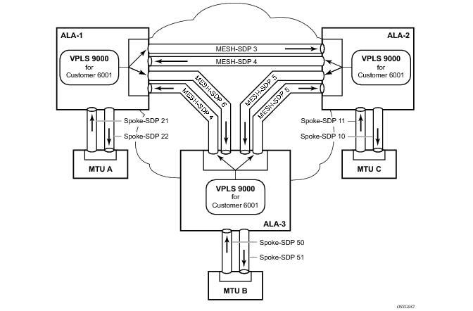
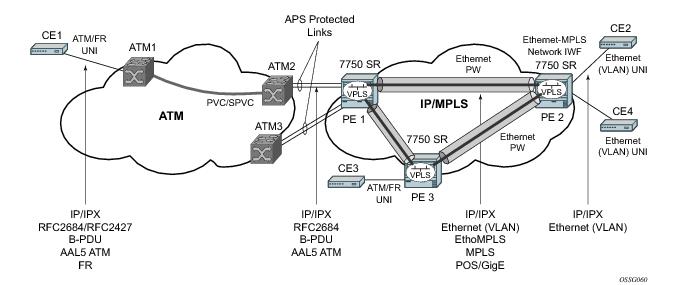
A spoke SDP connects a VPLS service between two sites and, in its simplest form, could be a single tunnel LSP. A set of ingress and egress VC labels are exchanged for each VPLS service instance to be transported over this LSP. The PE routers at each end treat this as a virtual spoke connection for the VPLS service in the same way as the PE-MTU connections. This architecture minimizes the signaling overhead and avoids a full mesh of VCs and LSPs between the two metro networks.
Figure 79 displays an example of a distributed VPLS service configuration of spoke and mesh SDPs (uni-directional tunnels) between routers and MTUs.
*A:ALA-48>config>service>vpls>sap# info
----------------------------------------------
...
exit
ingress
scheduler-policy "SLA1"
scheduler-override
scheduler "sched1" create
parent weight 3 cir-weight 3
exit
exit
policer-control-policy "SLA1-p"
policer-control-override create
max-rate 50000
exit
qos 100 multipoint-shared
queue-override
queue 1 create
rate 1500000 cir 2000
exit
exit
policer-override
policer 1 create
rate 10000
exit
exit
exit
egress
scheduler-policy "SLA1"
policer-control-policy "SLA1-p"
policer-control-override create
max-rate 60000
exit
qos 100
queue-override
queue 1 create
adaptation-rule pir max cir max
exit
exit
policer-override
policer 1 create
mbs 2000 kilobytes
exit
exit
filter ip 10
exit
----------------------------------------------
*A:ALA-48>config>service>vpls>sap#
Use the following CLI syntax to create a mesh or spoke SDP bindings with a distributed VPLS service. SDPs must be configured prior to binding. Refer to the
Services Overview Guide for information about creating SDPs.
mesh-sdp sdp-id[:
vc-id] [vc-type {ether | vlan}]
spoke-sdp sdp-id:
vc-id [vc-type {ether | vlan}] [split-horizon-group
group-name]
*A:ALA-1>config>service# info
----------------------------------------------
...
vpls 9000 customer 6 create
description "This is a distributed VPLS."
def-mesh-vc-id 750
stp
shutdown
exit
sap 1/2/5:0 create
exit
spoke-sdp 2:22 create
exit
mesh-sdp 5:750 create
exit
mesh-sdp 7:750 create
exit
no shutdown
exit
----------------------------------------------
*A:ALA-1>config>service#
*A:ALA-2>config>service# info
----------------------------------------------
...
vpls 9000 customer 6 create
description "This is a distributed VPLS."
def-mesh-vc-id 750
stp
shutdown
exit
sap 1/1/2:22 create
exit
spoke-sdp 2:22 create
exit
mesh-sdp 5:750 create
exit
mesh-sdp 7:750 create
exit
no shutdown
exit
----------------------------------------------
*A:ALA-3>config>service# info
----------------------------------------------
...
vpls 9000 customer 6 create
description "This is a distributed VPLS."
def-mesh-vc-id 750
stp
shutdown
exit
sap 1/1/3:33 create
exit
spoke-sdp 2:22 create
exit
mesh-sdp 5:750 create
exit
mesh-sdp 7:750 create
exit
no shutdown
exit
----------------------------------------------
*A:ALA-3>config>service#
NOTE: The administratively down state allows a loop to form within the VPLS.
Range: shutdown or
no shutdown
Default: no shutdown (spoke SDP admin up)
Default: (automatically generated)
Range: 0 to 255 (240 largest value, in increments of 16)
The spoke SDP edge-port command is used to reduce the time it takes a spoke SDP to reach the forwarding state when the spoke SDP is on the edge of the network, and thus has no further STP bridge to handshake with.
The edge-port command is used to initialize the internal OPER_EDGE variable. At any time, when OPER_EDGE is false on a spoke SDP, the normal mechanisms are used to transition to the forwarding state (see
Forward Delay ). When OPER_EDGE is true, STP assumes that the remote end agrees to transition to the forwarding state without actually receiving a BPDU with an agreement flag set.
The spoke SDP edge-port command is used to instruct STP to dynamically decide whether the spoke SDP is connected to another bridge.
The spoke SDP link-type command instructs STP on the maximum number of bridges behind this spoke SDP. If there is only a single bridge, transitioning to forwarding state will be based on handshaking (fast transitions). If more than two bridges are connected by a shared media, their spoke SDPs should all be configured as shared, and timer-based transitions are used.
|
•
|
VPLS state administratively down
|
Table 12 shows differences between dot1D and PVST Ethernet BPDU encapsulations based on the interface encap-type field:
|
•
|
Dot1d specifies that the switch is currently sending IEEE 802.1D standard BPDUs. The BPDUs will be tagged or non-tagged based on the encapsulation type of the egress interface and the encapsulation value defined in the spoke SDP. A spoke SDP defined on an interface with encapsulation type dot1q will continue in the dot1d BPDU encapsulation state until a PVST encapsulated BPDU is received, after which the spoke SDP will convert to the PVST encapsulation state. Each received BPDU must be properly IEEE 802.1q tagged if the interface encapsulation type is defined to dot1q.
|
|
•
|
PVST specifies that the switch is currently sending proprietary encapsulated BPDUs. PVST BPDUs are only supported on Ethernet interfaces with the encapsulation type set to dot1q. The spoke SDP continues in the PVST BPDU encapsulation state until a dot1d encapsulated BPDU is received, in which case the spoke SDP reverts to the dot1d encapsulation state. Each received BPDU must be properly IEEE 802.1q tagged with the encapsulation value defined for the spoke SDP.
|
*A:ALA-1>config>service# info
----------------------------------------------
...
vpls 800 customer 6001 vpn 700 create
description "VPLS with split horizon for DSL"
stp
shutdown
exit
spoke-sdp 51:15 split-horizon-group DSL-group1 create
exit
split-horizon-group DSL-group1
description "Split horizon group for DSL"
exit
no shutdown
exit
...
----------------------------------------------
*A:ALA-1>config>service#
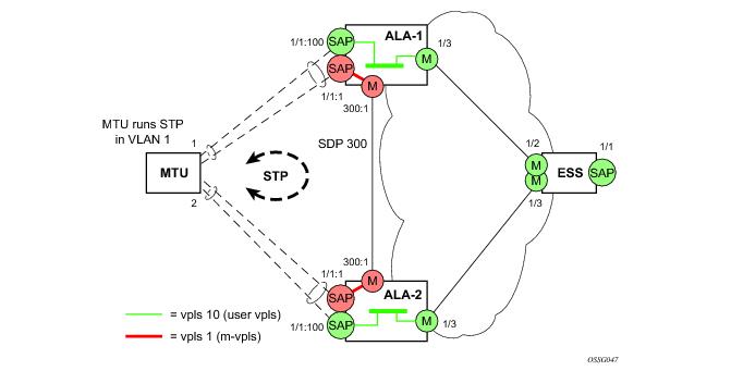
Before configuring a management VPLS, first read VPLS Redundancy for an introduction to the concept of management VPLS and SAP redundancy.
|
CLI Syntax:
|
vpls service-id customer customer-id [m-vpls] create
|
*A:ALA-1>config>service# info
----------------------------------------------
...
sdp 300 mpls create
far-end 10.0.0.20
lsp "toALA-A2"
no shutdown
exit
vpls 1 customer 1 m-vpls create
sap 1/1/1:1 create
managed-vlan-list
range 100-1000
exit
exit
mesh-sdp 300:1 create
exit
stp
exit
no shutdown
exit
...
----------------------------------------------
*A:ALA-1>config>service#
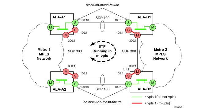
This section provides a brief overview of the tasks that must be performed to configure a management VPLS for spoke SDP protection and provides the CLI commands, see Figure 81. The tasks below should be performed on all four nodes providing the protected VPLS service.
Before configuring a management VPLS, first read
Configuring a VPLS SAP for an introduction to the concept of management VPLS and spoke SDP redundancy.
|
CLI Syntax:
|
vpls service-id customer customer-id [m-vpls] create
|
*A:ALA-A1>config>service# info
----------------------------------------------
...
sdp 100 mpls create
far-end 10.0.0.30
lsp "toALA-B1"
no shutdown
exit
sdp 300 mpls create
far-end 10.0.0.20
lsp "toALA-A2"
no shutdown
exit
vpls 101 customer 1 m-vpls create
spoke-sdp 100:1 create
exit
meshspoke-sdp 300:1 create
exit
stp
exit
no shutdown
exit
...
----------------------------------------------
*A:ALA-A1>config>service#
|
CLI Syntax:
|
vpls service-id customer customer-id [m-vpls] create
|
*A:ALA-A1>config>service# info
----------------------------------------------
...
sdp 101 mpls create
far-end 10.0.0.30
lsp "1toALA-B1"
no shutdown
exit
sdp 102 mpls create
far-end 10.0.0.30
lsp "2toALA-B1"
no shutdown
exit
...
vpls 101 customer 1 m-vpls create
spoke-sdp 101:1 create
stp
path-cost 1
exit
exit
mesh-sdp 300:1 create
exit
stp
exit
no shutdown
exit
vpls 102 customer 1 m-vpls create
spoke-sdp 102:2 create
stp
path-cost 1000
exit
exit
mesh-sdp 300:2 create
exit
stp
exit
no shutdown
exit
...
----------------------------------------------
*A:ALA-A1>config>service#
*A:ALA-A2>config>service# info
----------------------------------------------
...
sdp 101 mpls create
far-end 10.0.0.40
lsp "1toALA-B2"
no shutdown
exit
sdp 102 mpls create
far-end 10.0.0.40
lsp "2toALA-B2"
no shutdown
exit
...
vpls 101 customer 1 m-vpls create
spoke-sdp 101:1 create
stp
path-cost 1000
exit
exit
mesh-sdp 300:1 create
exit
stp
exit
no shutdown
exit
vpls 102 customer 1 m-vpls create
spoke-sdp 102:2 create
stp
path-cost 1
exit
exit
mesh-sdp 300:2 create
exit
stp
exit
no shutdown
exit
...
----------------------------------------------
*A:ALA-A2>config>service#
*A:ALA-A1>config>service# info
----------------------------------------------
...
sdp 101 mpls create
far-end 10.0.0.10
lsp "1toALA-A1"
no shutdown
exit
sdp 102 mpls create
far-end 10.0.0.10
lsp "2toALA-A1"
no shutdown
exit
...
vpls 101 customer 1 m-vpls create
spoke-sdp 101:1 create
stp
path-cost 1
exit
exit
mesh-sdp 300:1 create
exit
stp
exit
no shutdown
exit
vpls 102 customer 1 m-vpls create
spoke-sdp 102:2 create
stp
path-cost 1000
exit
exit
mesh-sdp 300:2 create
exit
stp
exit
no shutdown
exit
...
----------------------------------------------
*A:ALA-A1>config>service#
*A:ALA-A2>config>service# info
----------------------------------------------
...
sdp 101 mpls create
far-end 10.0.0.20
lsp "1toALA-B2"
no shutdown
exit
sdp 102 mpls create
far-end 10.0.0.20
lsp "2toALA-B2"
no shutdown
exit
...
vpls 101 customer 1 m-vpls create
spoke-sdp 101:1 create
stp
path-cost 1000
exit
exit
mesh-sdp 300:1 create
exit
stp
exit
no shutdown
exit
vpls 102 customer 1 m-vpls create
spoke-sdp 102:2 create
stp
path-cost 1
exit
exit
mesh-sdp 300:2 create
exit
stp
exit
no shutdown
exit
...
----------------------------------------------
*A:ALA-A2>config>service#
*A:Dut-B>config>redundancy>multi-chassis# info
----------------------------------------------
peer 3.1.1.3 create
peer-name "Dut-C"
description "mcep-basic-tests"
source-address 2.1.1.2
mc-endpoint
no shutdown
bfd-enable
system-priority 50
exit
no shutdown
exit
----------------------------------------------
*A:Dut-B>config>redundancy>multi-chassis#
*A:Dut-B>config>service>vpls# info
----------------------------------------------
fdb-table-size 20000
send-flush-on-failure
stp
shutdown
exit
endpoint "mcep-t1" create
no suppress-standby-signaling
block-on-mesh-failure
mc-endpoint 1
mc-ep-peer Dut-C
exit
exit
mesh-sdp 201:1 vc-type vlan create
exit
mesh-sdp 211:1 vc-type vlan create
exit
spoke-sdp 221:1 vc-type vlan endpoint "mcep-t1" create
stp
shutdown
exit
block-on-mesh-failure
precedence 1
exit
spoke-sdp 231:1 vc-type vlan endpoint "mcep-t1" create
stp
shutdown
exit
block-on-mesh-failure
precedence 2
exit
no shutdown
----------------------------------------------
*A:Dut-B>config>service>vpls#
:Dut-C>config>redundancy>multi-chassis# info
----------------------------------------------
peer 2.1.1.2 create
peer-name "Dut-B"
description "mcep-basic-tests"
source-address 3.1.1.3
mc-endpoint
no shutdown
bfd-enable
system-priority 21
exit
no shutdown
exit
----------------------------------------------
*A:Dut-C>config>redundancy>multi-chassis#
*A:Dut-C>config>service>vpls# info
----------------------------------------------
fdb-table-size 20000
send-flush-on-failure
stp
shutdown
exit
endpoint "mcep-t1" create
no suppress-standby-signaling
block-on-mesh-failure
mc-endpoint 1
mc-ep-peer Dut-B
exit
exit
mesh-sdp 301:1 vc-type vlan create
exit
mesh-sdp 311:1 vc-type vlan create
exit
spoke-sdp 321:1 vc-type vlan endpoint "mcep-t1" create
stp
shutdown
exit
block-on-mesh-failure
precedence 3
exit
spoke-sdp 331:1 vc-type vlan endpoint "mcep-t1" create
stp
shutdown
exit
block-on-mesh-failure
exit
no shutdown
----------------------------------------------
*A:Dut-C>config>service>vpls#
*A:Dut-D>config>redundancy>multi-chassis# info
----------------------------------------------
peer 5.1.1.5 create
peer-name "Dut-E"
description "mcep-basic-tests"
source-address 4.1.1.4
mc-endpoint
no shutdown
bfd-enable
system-priority 50
passive-mode
exit
no shutdown
exit
----------------------------------------------
*A:Dut-D>config>redundancy>multi-chassis#
*A:Dut-D>config>service>vpls# info
----------------------------------------------
fdb-table-size 20000
propagate-mac-flush
stp
shutdown
exit
endpoint "mcep-t1" create
block-on-mesh-failure
mc-endpoint 1
mc-ep-peer Dut-E
exit
exit
mesh-sdp 401:1 vc-type vlan create
exit
spoke-sdp 411:1 vc-type vlan endpoint "mcep-t1" create
stp
shutdown
exit
block-on-mesh-failure
precedence 2
exit
spoke-sdp 421:1 vc-type vlan endpoint "mcep-t1" create
stp
shutdown
exit
block-on-mesh-failure
precedence 1
exit
mesh-sdp 431:1 vc-type vlan create
exit
no shutdown
----------------------------------------------
*A:Dut-D>config>service>vpls#
*A:Dut-E>config>redundancy>multi-chassis# info
----------------------------------------------
peer 4.1.1.4 create
peer-name "Dut-D"
description "mcep-basic-tests"
source-address 5.1.1.5
mc-endpoint
no shutdown
bfd-enable
system-priority 22
passive-mode
exit
no shutdown
exit
----------------------------------------------
*A:Dut-E>config>redundancy>multi-chassis#
*A:Dut-E>config>service>vpls# info
----------------------------------------------
fdb-table-size 20000
propagate-mac-flush
stp
shutdown
exit
endpoint "mcep-t1" create
block-on-mesh-failure
mc-endpoint 1
mc-ep-peer Dut-D
exit
exit
spoke-sdp 501:1 vc-type vlan endpoint "mcep-t1" create
stp
shutdown
exit
block-on-mesh-failure
precedence 3
exit
spoke-sdp 511:1 vc-type vlan endpoint "mcep-t1" create
stp
shutdown
exit
block-on-mesh-failure
exit
mesh-sdp 521:1 vc-type vlan create
exit
mesh-sdp 531:1 vc-type vlan create
exit
no shutdown
----------------------------------------------
*A:Dut-E>config>service>vpls#
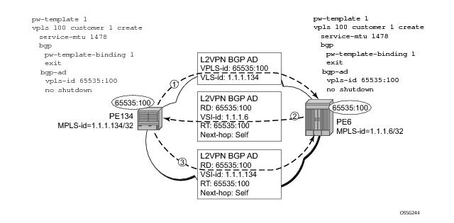
Using Figure 84, assume PE6 was previously configured with VPLS 100 as indicated by the configurations lines in the upper right. The BGP AD process will commence after PE134 is configured with the VPLS 100 instance as shown in the upper left. This shows a very basic and simple BGP AD configuration. The minimum requirement for enabling BGP AD on a VPLS instance is configuring the VPLS-ID and point to a pseudowire template.
PE134>config>service>vpls>bgp-ad#
[no] shutdown - Administratively enable/disable BGP auto-discovery
vpls-id - Configure VPLS-ID
vsi-id + Configure VSI-id
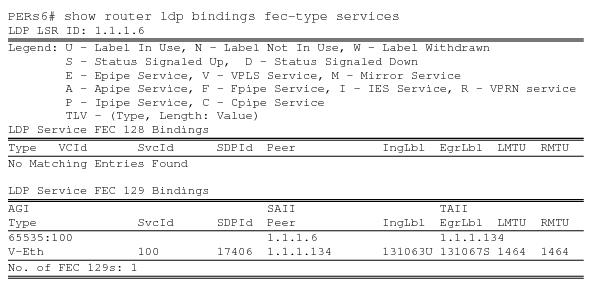
PE134># show service l2-route-table
=======================================================================
Services: L2 Route Information - Summary Service
=======================================================================
Svc Id L2-Routes (RD-Prefix) Next Hop Origin
Sdp Bind Id
-----------------------------------------------------------------------
100 65535:100-1.1.1.6 1.1.1.6 BGP-L2
17406:4294967295
-----------------------------------------------------------------------
No. of L2 Route Entries: 1 =======================================================================
PERs6>#
PERs6># show service l2-route-table
=======================================================================
Services: L2 Route Information - Summary Service
=======================================================================
Svc Id L2-Routes (RD-Prefix) Next Hop Origin
Sdp Bind Id
-----------------------------------------------------------------------
100 65535:100-1.1.1.134 1.1.1.134 BGP-L2
17406:4294967295
-----------------------------------------------------------------------
No. of L2 Route Entries: 1
=======================================================================
PERs6>#
PERs6# show service sdp-using
===============================================================================
SDP Using
===============================================================================
SvcId SdpId Type Far End Opr S* I.Label E.Label
-------------------------------------------------------------------------------
100 17406:4294967295 BgpAd 1.1.1.134 Up 131063 131067
-------------------------------------------------------------------------------
Number of SDPs : 1
===============================================================================
* indicates that the corresponding row element may have been truncated.
Figure 86 below shows the different detailed phases of the LDP signaling path, post BGP AD completion. It also indicates how some fields can be auto generated when they are not specified in the configuration.
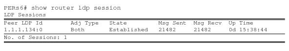
The first command will display the LDP peering relationships that have been established (Figure 87). The type of adjacency is displayed in the “Adj Type” column. In this case the type is “Both” meaning link and targeted sessions have been successfully established.
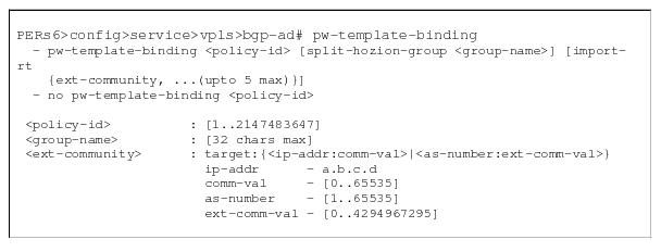
The pw-template is defined under the top level service command (config>service# pw-template) and specifies whether to use an automatically generated SDP or manually configured SDP. It also provides the set of parameters required for establishing the pseudowire (SDP binding) as displayed in
Figure 89.
A pw-template-binding command configured within the VPLS service under the
bgp-ad sub-command is a pointer to the pw-template that should be used. If a VPLS service does not specify an import-rt list, then that binding applies to all route targets accepted by that VPLS. The
pw-template-bind command can select a different template on a per import-rt basis. It is also possible to specify specific pw-templates for some route targets with a VPLS service and use the single
pw-template-binding command to address all unspecified but accepted imported targets.
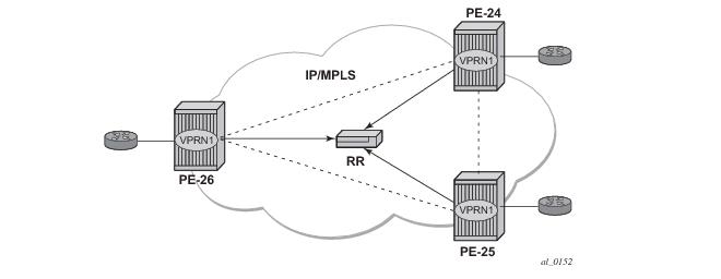
*A:PE24>config>service>vpls# info
----------------------------------------------
bgp
route-distinguisher 65024:600
route-target export target:65019:600 import target:65019:600
pw-template-binding 1
exit
bgp-vpls
max-ve-id 100
ve-name 24
ve-id 24
exit
no shutdown
exit
sap 1/1/20:600.* create
exit
no shutdown
----------------------------------------------
*A:PE24>config>service>vpls#
*A:PE25>config>service>vpls# info
----------------------------------------------
bgp
route-distinguisher 65025:600
route-target export target:65019:600 import target:65019:600
pw-template-binding 1
exit
bgp-vpls
max-ve-id 100
ve-name 25
ve-id 25
exit
no shutdown
exit
sap 1/1/19:600.* create
exit
no shutdown
----------------------------------------------
*A:PE25>config>service>vpls#
*A:PE26>config>service>vpls# info
----------------------------------------------
bgp
route-distinguisher 65026:600
route-target export target:65019:600 import target:65019:600
pw-template-binding 1
exit
bgp-vpls
max-ve-id 100
ve-name 26
ve-id 26
exit
no shutdown
exit
sap 5/2/20:600.* create
exit
no shutdown
----------------------------------------------
*A:PE26>config>service>vpls#
|
CLI Syntax:
|
config>service>vpls# interface ip-int-name
address ip-address[/ mask] [ netmask] arp-timeout seconds
description description-string
mac ieee-address
no shutdown static-arp ip-address ieee-address
|
A:ALA-49>config>service>vpls>interface# info detail
---------------------------------------------
no description
mac 14:31:ff:00:00:00
address 123.231.10.10/24
no arp-timeout
no shutdown
---------------------------------------------
A:ALA-49>config>service>vpls>interface#
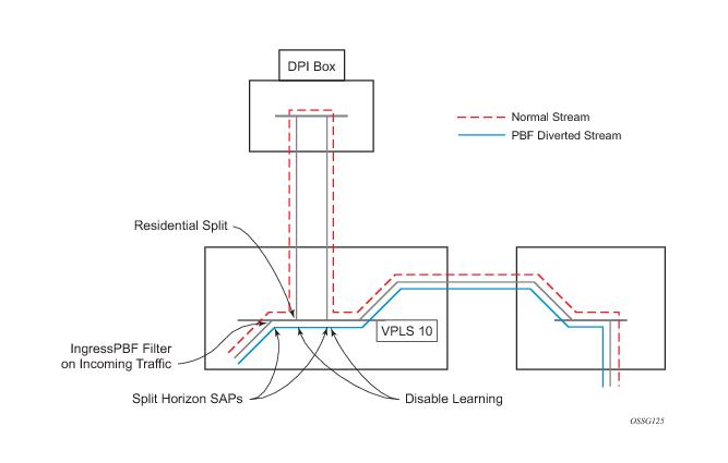
Figure 92 shows an example to configure policy-based forwarding for deep packet inspection on a VPLS service. For information about configuring filter policies, refer to the 7750 SR OS Router Configuration Guide.
*A:ALA-48>config>service# info
----------------------------------------------
...
vpls 10 customer 1 create
service-mtu 1400
split-horizon-group "dpi" residential-group create
exit
split-horizon-group "split" create
exit
stp
shutdown
exit
igmp-host-tracking
expiry-time 65535
no shutdown
exit
sap 1/1/21:1 split-horizon-group "split" create
disable-learning
static-mac 00:00:00:31:11:01 create
exit
sap 1/1/22:1 split-horizon-group "dpi" create
disable-learning
static-mac 00:00:00:31:12:01 create
exit
sap 1/1/23:5 create
static-mac 00:00:00:31:13:05 create
exit
no shutdown
exit
...
----------------------------------------------
*A:ALA-48>config>service#
*A:ALA-48>config>filter# info
----------------------------------------------
...
mac-filter 100 create
default-action forward
entry 10 create
match
dot1p 7 7
exit
log 101
action forward sap 1/1/22:1
exit
exit
...
----------------------------------------------
*A:ALA-48>config>filter#
*A:ALA-48>config>service# info
----------------------------------------------
...
vpls 10 customer 1 create
service-mtu 1400
split-horizon-group "dpi" residential-group create
exit
split-horizon-group "split" create
exit
stp
shutdown
exit
igmp-host-tracking
expiry-time 65535
no shutdown
exit
sap 1/1/5:5 split-horizon-group "split" create
ingress
filter mac 100
exit
static-mac 00:00:00:31:15:05 create
exit
sap 1/1/21:1 split-horizon-group "split" create
disable-learning
static-mac 00:00:00:31:11:01 create
exit
sap 1/1/22:1 split-horizon-group "dpi" create
disable-learning
static-mac 00:00:00:31:12:01 create
exit
sap 1/1/23:5 create
static-mac 00:00:00:31:13:05 create
exit
spoke-sdp 3:5 create
exit
no shutdown
exit
....
----------------------------------------------
*A:ALA-48>config>service#
When configuring a VPLS E‑Tree service the etree keyword must be specified when the VPLS service is created. This is the first operation required before any SAPs or SDPs are added to the service, since the E‑Tree service type affects the operations of the SAPs and SDP bindings.
*A:ALA-48>config>service# info
----------------------------------------------
...
service vpls 2005 etree customer 1 create
sap 1/1/1:2005 leaf-ac create
exit
sap 1/1/7:2006.200 root-leaf-tag leaf-tag 2007 create
exit
sap 1/1/7:0.* create
exit
spoke-sdp 12:2005 vc-type vlan root-leaf-tag create
no shutdow
exit
spoke-sdp 12:2006 leaf-ac create
no shutdown
exit
no shutdown
exit
....
*A:ALA-48>config>service# info
----------------------------------------------
You can change existing service parameters. The changes are applied immediately.
To display a list of services, use the show service service-using vpls command. Enter the parameter such as description, SAP, SDP, and/or service-MTU command syntax, and then enter the new information.
*A:ALA-1>config>service>vpls# info
----------------------------------------------
description "This is a different description."
disable-learning
disable-aging
discard-unknown
local-age 500
remote-age 1000
stp
shutdown
exit
sap 1/1/5:22 create
description "VPLS SAP"
exit
spoke-sdp 2:22 create
exit
no shutdown
----------------------------------------------
*A:ALA-1>config>service>vpls#
Example:
config>service# vpls 1
config>service>vpls# shutdown
config>service>vpls# exit
sap sap-id [split-horizon-group
group-name]
Example:
config>service# vpls 1
config>service>vpls# shutdown
config>service>vpls# exit
Example:
config>service# vpls 1
config>service>vpls# no shutdown
config>service>vpls# exit