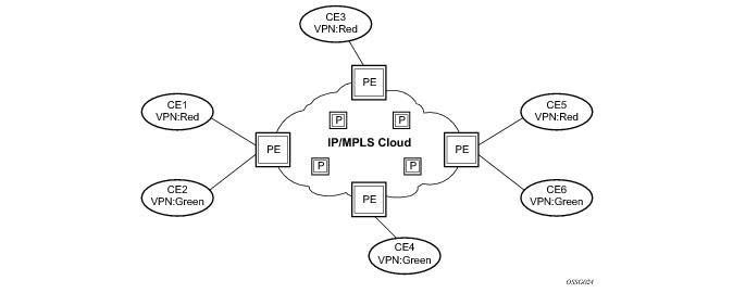
RFC 2547b is an extension to the original RFC 2547, BGP/MPLS VPNs, which details a method of distributing routing information using BGP and MPLS forwarding data to provide a Layer 3 Virtual Private Network (VPN) service to end customers.
BGP is used with BGP extensions mentioned in Routing Prerequisites to distribute VPRN routing information across the service provider’s network.
The route distinguisher (RD) is an 8-byte value consisting of two major fields, the Type field and
Value field. The
Type field determines how the
Value field should be interpreted. The 7750 SR implementation supports the three (3)
Type values as defined in the standard.
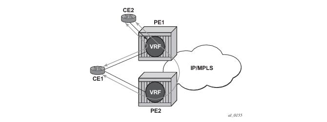
Figure 9 displays a basic topology that could use eiBGP load balancing. In this topology CE1 is dual homed and thus reachable by two separate PE routers. CE 2 (a site in the same VPRN) is also attached to PE1. With eiBGP load balancing, PE1 will utilize its own local IPv4 nexthop as well as the route advertised by MP-BGP, by PE2.
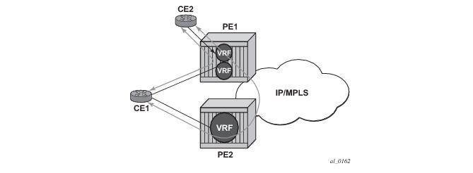
Another example displayed in Figure 10 shows an extra net VPRN (VRF). The traffic ingressing the PE that should be load balanced is part of a second VPRN and the route over which the load balancing is to occur is part of a separate VPRN instance and are leaked into the second VPRN by route policies.
VPN-IP routes imported into a VPRN, have the protocol type bgp-vpn to denote that it is an VPRN route. This can be used within the route policy match criteria.
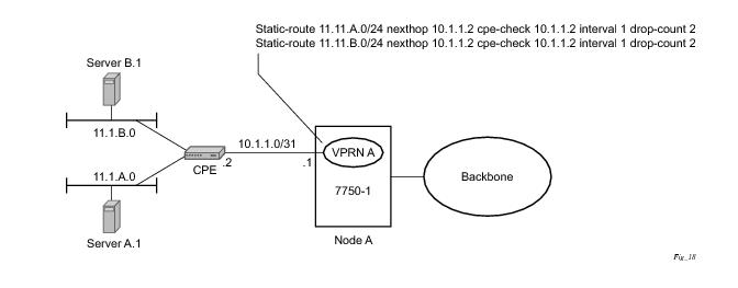
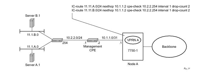
Static routes are used within many IES and VPRN services. Unlike dynamic routing protocols, there is no way to change the state of routes based on availability information for the associated CPE. CPE connectivity check adds flexibility so that unavailable destinations will be removed from the VPRN routing tables dynamically and minimize wasted bandwidth.
RT Constraint is supported only by the base router BGP instance. When the family command at the BGP router group or neighbor CLI context includes the
route-target keyword, the RT Constraint capability is negotiated with the associated set of EBGP and IBGP peers.
A, 7750 SR, or may be configured to send the default RTC route to any RTC peer. This is done using the new
default-route-target group/neighbor CLI command. The default RTC route is a special type of RTC route that has zero prefix length. Sending the default RTC route to a peer conveys a request to receive all VPN routes (regardless of route target extended community) from that peer. The default RTC route is typically advertised by a route reflector to its clients. The advertisement of the default RTC route to a peer does not suppress other more specific RTC routes from being sent to that peer.
Note: These advertisement rules do not handle hierarchical RR topologies properly. This is a limitation of the current RT constraint standard.
Note: This applies whether or not P1 advertised the best route for the default RTC prefix.
Note: This applies whether or not I1 advertised the best route for A.
Note: This applies only if E1 advertised the best route for A.
If all IP prefixes require backup path protection, use a combination of the BGP instance-level backup-path and VPRN-level
enable-bgp-vpn-backup commands. The VPRN BGP
backup-path command enables BGP fast reroute for all IPv4 prefixes and/or all IPv6 prefixes that have a best path through a VPRN BGP peer. The VPRN-level
enable-bgp-vpn-backup command enables BGP fast reroute for all IPv4 prefixes and/or all IPv6 prefixes that have a best path through a remote PE peer.
If only some IP prefixes require backup path protection, use route policies to apply the install-backup-path action to the best paths of the IP prefixes requiring protection. See BGP Fast Reroute section of the 7750 SR OS Routing Protocols Guide for more information.
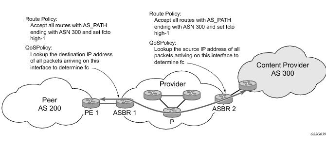
Figure 12 shows an example of an ISP that has an agreement with the content provider managing AS300 to provide traffic sourced and terminating within AS300 with differentiated service appropriate to the content being transported. In this example we presume that ASBR1 and ASBR2 mark the DSCP of packets terminating and sourced, respectively, in AS300 so that other nodes within the ISP’s network do not need to rely on QPPB to determine the correct forwarding-class to use for the traffic. Note however, that the DSCP or other COS markings could be left unchanged in the ISP’s network and QPPB used on every node.
fc fc-name [priority {low | high}]
config>router>policy-options
begin
community gold members 300:100
policy-statement qppb_policy
entry 10
from
protocol bgp
community gold
exit
action accept
fc h1 priority high
exit
exit
exit
commit
The fc command is supported with all existing from and to match conditions in a route policy entry and with any action other than reject, it is supported with next-entry, next-policy and accept actions. If a next-entry or next-policy action results in multiple matching entries then the last entry with a QPPB action determines the forwarding class and priority.
A route policy that includes the fc command in one or more entries can be used in any import or export policy but the
fc command has no effect except in the following types of policies:
|
•
|
static-route {ip-prefix/ prefix-length| ip-prefix netmask} [fc fc-name [priority {low | high}]] next-hop ip-int-name| ip-address
|
|
•
|
static-route {ip-prefix/ prefix-length| ip-prefix netmask} [fc fc-name [priority {low | high}]] indirect ip-address
|
This feature uses a qos keyword to the
show>router>route-table command. When this option is specified the output includes an additional line per route entry that displays the forwarding class and priority of the route. If a route has no fc and priority information then the third line is blank. The following CLI shows an example:
show router route-table [family
] [ip-prefix[/prefix-length]] [longer
| exact
] [protocol
protocol-name] qos
A:Dut-A# show router route-table 10.1.5.0/24 qos
===============================================================================
Route Table (Router: Base)
===============================================================================
Dest Prefix Type Proto Age Pref
Next Hop[Interface Name] Metric
QoS
-------------------------------------------------------------------------------
10.1.5.0/24 Remote BGP 15h32m52s 0
PE1_to_PE2 0
h1, high
-------------------------------------------------------------------------------
No. of Routes: 1
===============================================================================
A:Dut-A#
To enable QoS classification of ingress IP packets on an interface based on the QoS information associated with the routes that best match the packets the qos-route-lookup command is necessary in the configuration of the IP interface. The
qos-route-lookup command has parameters to indicate whether the QoS result is based on lookup of the source or destination IP address in every packet. There are separate qos-route-lookup commands for the IPv4 and IPv6 packets on an interface, which allows QPPB to enabled for IPv4 only, IPv6 only, or both IPv4 and IPv6. Note however, current QPPB based on a source IP address is not supported for IPv6 packets nor is it supported for ingress subscriber management traffic on a group interface.
When QPPB is enabled on a SAP IP interface the forwarding class of a packet may change from fc1, the original
fc determined by the SAP ingress QoS policy to fc2, the new fc determined by QPPB. In the ingress datapath SAP ingress QoS policies are applied in the first P chip and route lookup/QPPB occurs in the second P chip. This has the implications listed below:
|
•
|
The profile state of a SAP ingress packet that matches a QPPB route depends on the configuration of fc2 only. If the de-1-out-profile flag is enabled in fc2 and fc2 is not mapped to a priority mode queue then the packet will be marked out of profile if its DE bit = 1. If the profile state of fc2 is explicitly configured (in or out) and fc2 is not mapped to a priority mode queue then the packet is assigned this profile state. In both cases there is no consideration of whether or not fc1 was mapped to a priority mode queue.
|
|
•
|
The priority of a SAP ingress packet that matches a QPPB route depends on several factors. If the de-1-out-profile flag is enabled in fc2 and the DE bit is set in the packet then priority will be low regardless of the QPPB priority or fc2 mapping to profile mode queue, priority mode queue or policer. If fc2 is associated with a profile mode queue then the packet priority will be based on the explicitly configured profile state of fc2 (in profile = high, out profile = low, undefined = high), regardless of the QPPB priority or fc1 configuration. If fc2 is associated with a priority mode queue or policer then the packet priority will be based on QPPB (unless DE=1), but if no priority information is associated with the route then the packet priority will be based on the configuration of fc1 (if fc1 mapped to a priority mode queue then it is based on DSCP/IP prec/802.1p and if fc1 mapped to a profile mode queue then it is based on the profile state of fc1).
|
Table 10 summarizes these interactions.
oper-group g1 create
vpls 1 customer 1 create
allow-ip-int-bind
stp
shutdown
exit
service-name "v1"
sap 1/1/1:2001 create
oper-group g1
eth-cfm
mep domain 1 association 1 direction down
ccm-enable
no shutdown
exit
exit
sap 1/1/2:2001 create
exit
sap 1/1/3:2001 create
exit
no shutdown
vprn 2001 customer 1 create
interface "i2001" create
address 21.1.1.1/24
monitor-oper-group "g1"
vpls "v1"
exit
no shutdown
exit
|
•
|
RFC 2684, Multiprotocol Encapsulation over ATM Adaptation Layer 5:
|
DSCP Name DSCP Value DSCP Value DSCP Value Label
Decimal Hexadecimal Binary
=============================================================
Default 0 0x00 0b000000 be
nc1 48 0x30 0b110000 h1
nc2 56 0x38 0b111000 nc
ef 46 0x2e 0b101110 ef
af11 10 0x0a 0b001010 assured
af12 12 0x0c 0b001100 assured
af13 14 0x0e 0b001110 assured
af21 18 0x12 0b010010 l1
af22 20 0x14 0b010100 l1
af23 22 0x16 0b010110 l1
af31 26 0x1a 0b011010 l1
af32 28 0x1c 0b011100 l1
af33 30 0x1d 0b011110 l1
af41 34 0x22 0b100010 h2
af42 36 0x24 0b100100 h2
af43 38 0x26 0b100110 h2
default* 0
|
•
|
The all parameter enables TTL propagation from the IP header into all labels in the stack, for VPN-IPv4 and VPN-IPv6 packets forwarded in the context of all VPRN services in the system.
|
|
•
|
The vc-only parameter reverts to the default behavior by which the IP TTL is propagated into the VC label but not to the transport labels in the stack. You can explicitly set the default behavior by configuring the vc-only value.
|
|
•
|
The none parameter disables the propagation of the IP TTL to all labels in the stack, including the VC label. This is needed for a transparent operation of UDP traceroute in VPRN inter-AS option B such that the ingress and egress ASBR nodes are not traced.
|
The 7750 SR VPRN supports the following PE to CE routing protocols:
The 7750 SR supports multiple mechanisms to provide transport tunnels for the forwarding of traffic between PE routers within the 2547bis network.
The 7750 SR VPRN implementation supports the use of:
The 7750 SR allows setting the maximum number of routes that can be accepted in the VRF for a VPRN service. There are options to specify a percentage threshold at which to generate an event that the VRF table is near full and an option to disable additional route learning when full or only generate an event.
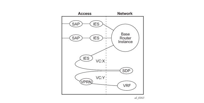
Figure 13 depicts traffic terminating on a specific IES or VPRN service that is identified by the
sdp-id and VC label present in the service packet.
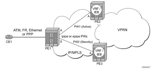
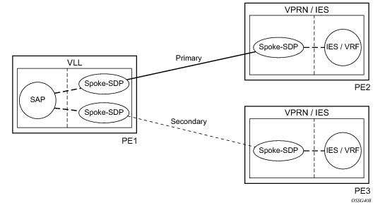
In Figure 14, PE1 terminates two spoke-SDPs that are bound to one SAP connected to CE1. PE1 chooses to forward traffic on one of the spoke SDPs (the active spoke-SDP), while blocking traffic on the other spoke-SDP (the standby spoke-SDP) in the transmit direction. PE2 and PE3 take any spoke-SDPs for which PW forwarding standby has been signaled by PE1 to an operationally down state.
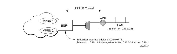
From a BNG perspective, the given PPPoE host is allocated a subnet (instead of /32) by RADIUS, external dhcp-server, or local-user-db. And locally, the host is associated with managed-route. This managed-route will be subset of the subscriber-interface subnet, and also, subscriber-host ip-address will be from managed-route range. The negotiation between BNG and CPE allows CPE to be allocated both ip-address and associated subnet.
The first option, referred to as Option-A (Figure 17), is considered inherent in any implementation. This method uses a back-to-back connection between separate VPRN instances in each AS. As a result, each VPRN instance views the inter-AS connection as an external interface to a remote VPRN customer site. The back-to-back VRF connections between the ASBR nodes require individual sub-interfaces, one per VRF.
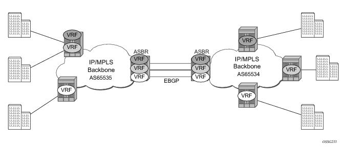
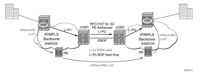
The second option, referred to as Option-B (Figure 18), relies heavily on the AS Boundary Routers (ASBRs) as the interface between the autonomous systems. This approach enhances the scalability of the eBGP VRF-to-VRF solution by eliminating the need for per-VPRN configuration on the ASBR(s). However it requires that the ASBR(s) provide a control plan and forwarding plane connection between the autonomous systems. The ASBR(s) are connected to the PE nodes in its local autonomous system using iBGP either directly or through route reflectors. This means the ASBR(s) receive all the VPRN information and will forward these VPRN updates, VPN-IPV4, to all its EBGP peers, ASBR(s), using itself as the next-hop. It also changes the label associated with the route. This means the ASBR(s) must maintain an associate mapping of labels received and labels issued for those routes. The peer ASBR(s) will in turn forward those updates to all local IBGP peers.
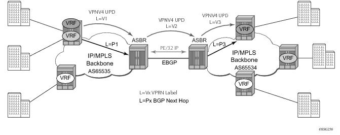
This form of inter-AS VPRNs does not require instances of the VPRN to be created on the ASBR, as in option-A, as a result there is less management overhead. This is also the most common form of Inter-AS VPRNs used between different service providers as all routes advertised between autonomous systems can be controlled by route policies on the ASBRs by the
config>router>bgp>transport-tunnel CLI command.
The third option, referred to as Option-C (Figure 19), allows for a higher scale of VPRNs across AS boundaries but also expands the trust model between ASNs. As a result this model is typically used within a single company that may have multiple ASNs for various reasons.
config>service>vprn>network-interface>port port-id
config>service>vprn>network-interface>lag
lag-id
config>service>vprn>network-interface>port port-id:qtag1
config>service>vprn>network-interface>lag
port-id:qtag1
config>service>vprn>network-interface>port port-id:qtag1.qtag2
config>service>vprn>network-interface>port
port-id:qtag1.*
config>service>vprn>network-interface>lag
port-id:qtag1.qtag2
config>service>vprn>network-interface>lag
port-id:qtag1.*
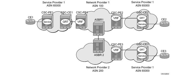
To use BGP-3107 as the label distribution protocol on the CSC interface, add the advertise-label ipv4 command to the BGP neighbor configuration. This command causes the capability to send and receive labeled-IPv4 routes {AFI=1, SAFI=4} to be negotiated with the CSC-CE peers.
To configure a VPRN to support CSC service, the carrier-carrier-vpn command must be enabled in its configuration. The command will fail if the VPRN has any existing SAP or spoke-SDP interfaces. A CSC interface can be added to a VPRN (using the
network-interface command) only if the
carrier-carrier-vpn command is present.
A VPRN service with the carrier-carrier-vpn command may be provisioned to use auto-bind, configured spoke SDPs or some combination. All SDP types are supported except for:
This feature is enabled within the VPRN service context under config>service>vprn>grt-lookup. This is an administrative context and provides the container under which all specific commands can be entered, except for policy definition. Policy definitions remain unchanged but are referenced from this context.
The enable-grt command establishes the basic functionality. When it is configured, any lookup miss in the VRF table will be resolved in the GRT, if available. By itself, this only provides part of the solution. Packet forwarding within GRT must understand how to route packets back to the proper node and to the specific VPRN from which the destination exists. Destination prefixes must be leaked from the VPRN to the GRT through the use of policy. Policies are created under the
config>router>policy-options hierarchy. By default, the number of prefixes leaked from the VPRN to the GRT is limited to five. The
export-limit command under the
grt-lookup hierarchy allows the service provider to override the default, or remove the limit.
Table 12 summarizes the logic that determines the label allocation method for an exported route.
To change the service label mode of the VPRN the config>service>vprn>label-mode {
vrf |
next-hop} command is used:
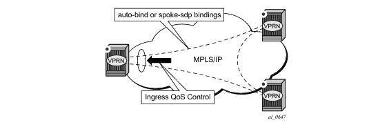
An ingress queue group must be configured and applied to the ingress network FP where the traffic is received for the VPRN. All traffic received on that FP for any binding in the VPRN (either automatically or statically configured) which is redirected to a policer in the FP queue group (using fp-redirect-qroup in the network QoS policy) will be controlled by that policer. As a result, the traffic from all such bindings is treated as a single entity (per forwarding class) with regard to ingress QoS control. Any
fp-redirect-group multicast-policer, broadcast-policer or
unknown-policer commands in the network QoS policy are ignored for this traffic (IP multicast traffic would use the ingress network queues or queue group related to the network interface).
configure
vprn
network
ingress
qos <network-policy-id> fp-redirect-group <queue-group-name>
instance <instance-id>
This is supported for all available transport tunnel types and is independent of the label mode (vrf or
next-hop) used within the VPRN. It is also supported for Carrier-Supporting-Carrier VPRNs.
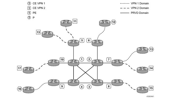
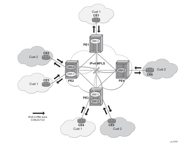
Figure 23 depicts an example of multicast in an IP-VPN application. The provider’s domain encompasses the core routers (1 through 4) and the edge routers (5 through 10). The various IP-VPN customers each have their own multicast domain, VPN-1 (CE routers 12, 13 and 16) and VPN-2 (CE Routers 11, 14, 15, 17 and 18). Multicast in this VPRN example, the VPN-1 data generated by the customer behind router 16 will be multicast only by PE 9 to PE routers 6 and 7 for delivery to CE routers 12 and 13 respectively. Data generated for VPN-2 generated by the customer behind router 15 will be forwarded by PE 8 to PE routers 5, 7 and 10 for delivery to CE routers 18, 11, 14 and 17 respectively.
Table 14 and
Table 15 describe the supported configuration combinations. If the CLI combination is not allowed, the system returns an error message. If the CLI command is marked as “ignored” in the table, the configuration is not blocked, but its value is ignored by the software.
For example, if auto-discovery is disabled, the c-mcast-signaling bgp command will fail with an error message stating:
If c-mcast-signaling is set to
bgp then
no auto-discovery will fail with an error message stating
When c-mcast-signaling is set to
bgp, S-PMSI A-D is always enabled (its configuration is ignored);
When auto-discovery is disabled, S-PMSI A-D is always disabled (its configuration is ignored).
When auto-discovery is enabled and c-multicast-signaling is set to
pim, S-PMSI A-D configuration value is used.
MVPN implementation based on the draft -Rosen can support membership auto discovery using BGP MDT-SAFI. A CLI option is provided per MVPN instance to enable auto discovery either using BGP MDT-SAFI or NG-MVPN. Only PIM-MDT is supported with BGP MDT-SAFI method.
Only one unique multicast flow is supported over each P2MP RSVP-TE or P2MP LDP LSP S-PMSI. Number of S-PMSI that can be initiated per MVPN instance is restricted by CLI command maximum-p2mp-spmsi. P2MP LSP S-PMSI cannot be used for more than one (S,G) stream (that is, multiple multicast flow) as number of S-PMSI per MVPN limit is reached. Multicast flows that cannot switch to S-PMSI remain on I-PMSI.
The multicast-traffic CLI command must be configured per LDP interface to enable P2MP LDP setup. P2MP LDP must also be configured as inclusive or selective (S-PMSI is for efficient data distribution and is optional) provider tunnel per MVPN to dynamically initiate P2MP LSP to leaf PE nodes learned via NG-MVPN auto-discovery signaling.
The SR OS allows an operator to configure wildcard S-PMSI for ng-MVPN (config>service>vprn>mvpn>pt>inclusive>wildcard-spmsi), using LDP and RSVP-TE in P‑instance. Support includes:
RSVP-TE/mLDP configuration under inclusive provider tunnel (config>service>vprn>mvpn>pt>inclusive) apply to wildcard S-PMSI when enabled.
OPERATIONAL NOTE: All SR OS routers with BGP peering session to the PE with RFC6625 support enabled must be upgraded to SR OS release 13.0 before the feature is enabled. Failure to do so will result in the following processing on a router with BGP peering session to an RFC6625-enabled PE:
OPERATIONAL NOTE: If UMH PE does not encode I-PMSI/S-PMSI A-D routes as per the above, or advertises both I-PMSI and wildcard S-PMSI with the tunnel information present, no interoperability can be achieved.
The feature uses procedures defined in RFC 7246: Multipoint Label Distribution Protocol In-Band Signaling in Virtual Routing and Forwarding (VRF) Table Context. On the receiver PE, PIM signaling is dynamically mapped to the P2MP LDP tree setup. On the source PE, signaling is handed back from the P2MP mLDP to the PIM. Due to dynamic mapping of multicast IP flow to P2MP LSP, provisioning and maintenance overhead is eliminated as multicast distribution services are added and removed from the VRF. Per (C-S, C-G) IP multicast state is also removed from the network, since P2MP LSPs are used to transport multicast flows.
Figure 24 illustrates dynamic mLDP signaling for IP multicast in VPRN.
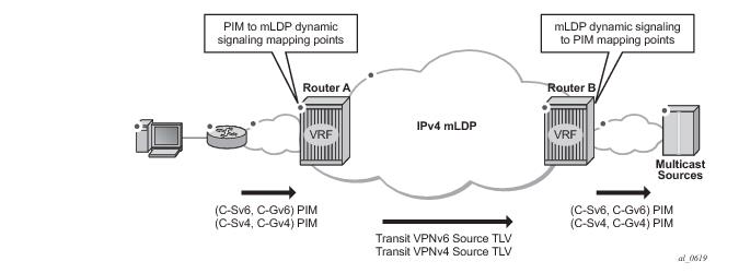
As illustrated in Figure 24, P2MP LDP LSP signaling is initiated from the receiver PE that receives PIM JOIN from a downstream router (Router A). To enable dynamic multicast signaling, the
p2mp-ldp-tree-join must be configured on PIM customer-facing interfaces for the given VPRN of Router A. This enables handover of multicast tree signaling from the PIM to the P2MP LDP LSP. Being a leaf node of the P2MP LDP LSP, Router A selects the upstream-hop as the root node of P2MP LDP FEC, based on a routing table lookup. If an ECMP path is available for a given route, then the number of trees are equally balanced towards multiple root nodes. The PIM joins are carried in the Transit Source PE (Router B), and multicast tree signaling is handed back to the PIM and propagated upstream as native-IP PIM JOIN toward C-instance multicast source.
UMH tunnel-status selection option must be enabled on the receiver PE for upstream fast failover. Primary and standby upstream PE pairs must be configured on the receiver PE to enable active redundant multicast flow to be received from the standby upstream PE.
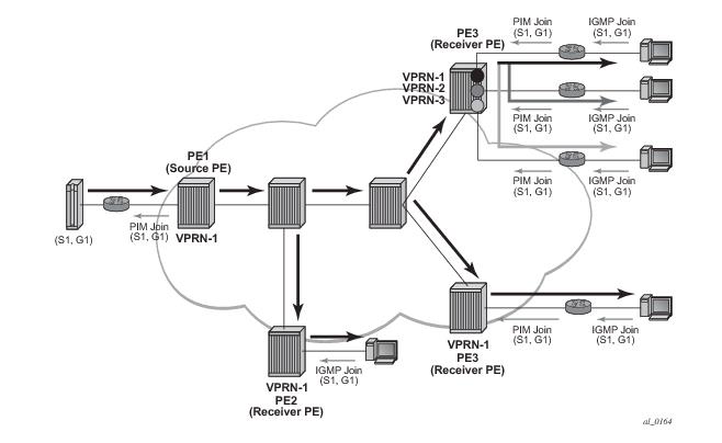
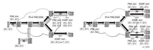
In Figure 26, VPRN-1 is the source VPRN instance and VPRN-2 and VPRN-3 are receiver VPRN instances. The PIM/IGMP JOIN received on VPRN-2 or VPRN-3 is for (S1, G1) multicast flow. Source S1 belongs to VPRN-1. Due to the route export policy in VPRN-1 and the import policy in VPRN-2 and VPRN-3, the receiver host in VPRN-2 or VPRN-3 can subscribe to the stream (S1, G1).
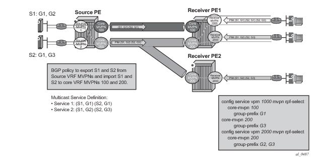
The architecture displayed in Figure 27 requires a source routing instance MVPN to place its multicast streams into one or more transit core routing instance MVPNs (each stream mapping to a single transit core instance only). It also requires receivers within each receiver routing instance MVPN to know which transit core routing instance MVPN they need to join for each of the multicast streams. To achieve this functionality, transit replication from a source routing instance MVPN onto a tunnel of a transit core routing instance MVPN on a source PE (see earlier sub-sections for MVPN topologies supporting transit replication on source PEs) and per-group mapping of multicast groups from receiver routing instance MVPNs to transit core routing instance MVPNs (as defined below) are required.
Figure 28 depicts a sample deployment.
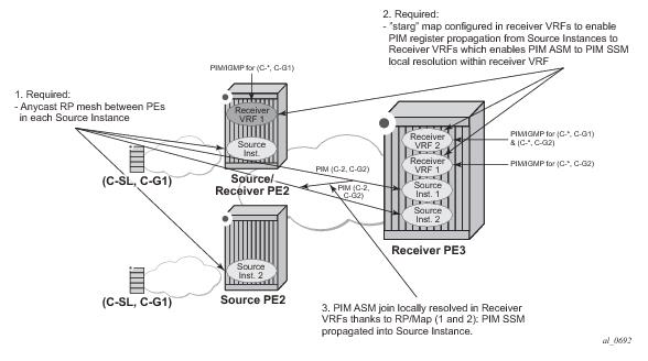
Figure 29 depicts PIM ASM extranet map support.
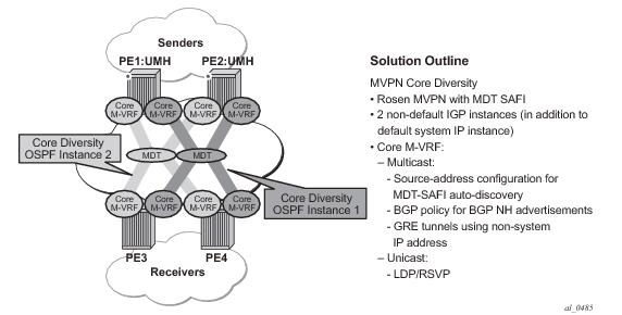
Figure 32 depicts Rosen MVPN core diversity deployment:
On source PEs (PE1: UMH, PE2: UMH in Figure 32), an MVPN is assigned to a non-default IGP core instance as follows:
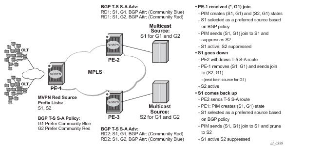
Figure 33 shows an operational example of multicast source geo-redundancy:
|
•
|
Each receiver PE has a BGP VRF import policy that sets local preference using match on Type-5 SA routes (new attribute mvpn-type 5) and standard community attribute value (as tagged by the Source PEs). Using policy statements that also include group address match, allows receiver PEs to select the best multicast source per group. The BGP VRF import policy must be applied as vrf-import under config>service>vprn>mvpn context. It must have default-action accept specified, or all MVPN routes other than those matched by specified entries will be rejected. In addition, it must have vrf-target as a community match condition, because vrf-target mvpn configuration is ignored when vrf-import policy is defined.
|
|
3.
|
Both intersite-shared enabled and disabled are supported. For intersite-shared enabled, operators must enable generation of Type-5 S-A routes even in the absence of receivers seen on Source PEs (intersite-shared persistent-type5-adv must be enabled).
|
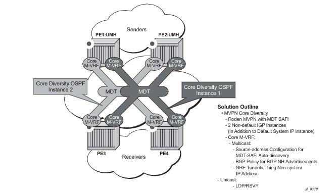
Figure 34 shows a Rosen MVPN core diversity deployment.
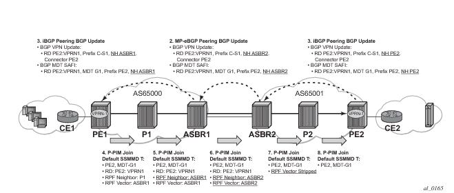
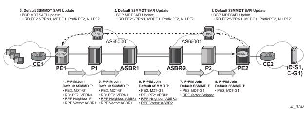
The RPF vector is added to a PIM join at a PE router when configure router pim rpfv option is enabled. P routers and ASBR routers must also have the option enabled to allow RPF Vector processing. If the option is not enabled, the RPF Vector is dropped and the PIM JOIN is processed as if the PIM Vector were not present.
When configure router pim rpfv mvpn option is enabled, Cisco routers need to be configured to include RD in an RPF vector using the following command:
ip multicast vrf vrf-name rpf proxy rd vector for interoperability. When Cisco routers are not configured to include RD in an RPF vector, operator should configure SROS router (if supported) using
configure router pim rpfv core mvpn: PIM joins received can be a mix of core and mvpn RPF vectors.
The RIB processing of specific routes can be prioritized through the use of the rib-priority command. This command allows specific routes to be prioritized through the protocol processing so that updates are propagated to the FIB as quickly as possible.
The rib-priority command can be configured within the VPRN instance of the OSPF or IS-IS routing protocols. For OSPF, a prefix list can be specified that identifies which route prefixes should be considered high priority. If the rib-priority high command is configured under an
VPRN>OSPF>area>interface context then all routes learned through that interface is considered high priority. For the IS-IS routing protocol, RIB prioritization can be either specified though a prefix-list or an IS-IS tag value. If a prefix list is specified than route prefixes matching any of the prefix list criteria will be considered high priority. If instead an IS-IS tag value is specified then any IS-IS route with that tag value will be considered high priority.