configure
subscriber-mgmt
authentication-policy "auth-policy-1" create
radius-server-policy "aaa-server-policy-1“
exit
exit
|
•
|
The fallback-action command specifies the action when no RADIUS server is available is configured direct in the config>subscr-mgmt>auth-plcy CLI context.
|
configure
subscriber-mgmt
radius-accounting-policy "acct-policy-1" create
radius-server-policy "aaa-server-policy-1“
exit
exit
Note: To avoid conflicts, the following CLI commands are ignored in the RADIUS accounting policy when a
radius-server-policy is attached:
configure
aaa
radius-server-policy "aaa-server-policy-1" create
description "Radius AAA server policy"
accept-script-policy "script-policy-2"
acct-request-script-policy "script-policy-3"
auth-request-script-policy "script-policy-1"
acct-on-off oper-state-change
servers
access-algorithm direct
retry 3
router "Base"
no source-address
hold-down-time sec 30
timeout sec 5
buffering
acct-interim min 60 max 3600 lifetime 5
acct-stop min 60 max 3600 lifetime 5
exit
server 1 name "server-1"
server 2 name “server-2”
exit
exit
exit
configure
router
radius-server
server "server-1" address 172.16.1.1 secret <shared secret> hash2 create
accept-coa
coa-script-policy "script-policy-4"
description "Radius server 1"
pending-requests-limit 4096
acct-port 1813
auth-port 1812
exit
server "server-2" address 172.16.1.2 secret <shared secret> hash2 create
accept-coa
coa-script-policy "script-policy-4"
description "Radius server 2"
pending-requests-limit 4096
acct-port 1813
auth-port 1812
exit
exit
exit
Note: To configure RADIUS CoA servers for use in Enhanced Subscriber Management, the server must be configured in the corresponding routing instance with the
accept-coa command enabled.
Note: It is recommended to migrate to the uniform RADIUS server configuration as described above to have additional functionality enabled.
configure
subscriber-mgmt
authentication-policy "auth-policy-1" create
radius-authentication-server
access-algorithm direct
hold-down-time 30
retry 3
no source-address
timeout 5
router "Base"
server 1 address 172.16.1.1 secret <shared secret> hash2 port 1812 pending-requests-limit 4096
server 2 address 172.16.1.2 secret <shared secret> hash2 port 1812 pending-requests-limit 4096
exit
accept-authorization-change
accept-script-policy "script-policy-2"
coa-script-policy "script-policy-4"
request-script-policy "script-policy-1"
exit
exit
Note: In legacy RADIUS server configuration, to configure RADIUS CoA servers for use in Enhanced Subscriber Management, the server must be configured in the authentication policy with the
accept-authorization-change command enabled. A CoA only server can be configured with the optional coa-only flag.
configure
subscriber-mgmt
radius-accounting-policy "acct-policy-1" create
radius-accounting-server
access-algorithm direct
retry 3
timeout 5
no source-address
router "Base"
server 1 address 172.16.1.1 secret <shared secret> hash2 port 1813
server 2 address 172.16.1.2 secret <shared secret> hash2 port 1813
exit
acct-request-script-policy "script-policy-3"
exit
exit
Note: Refer to section DHCP Principles for an explanation of DHCP and
DHCP Snooping for an explanation of DHCP snooping.
If the optional subscriber management authentication policy re-authentication command is enabled, DHCP authentication is performed at every DHCP lease renew request. Only dynamic DHCP sessions are subject to remote authentication. Statically provisioned hosts are not authenticated.
Change-of-Authorization (CoA) messages as defined by RFC 3576, Dynamic Authorization Extensions to Remote Authentication Dial In User Service (RADIUS), are supported. The goal of CoA messages is to provide a mechanism for “mid-session change” support through RADIUS.
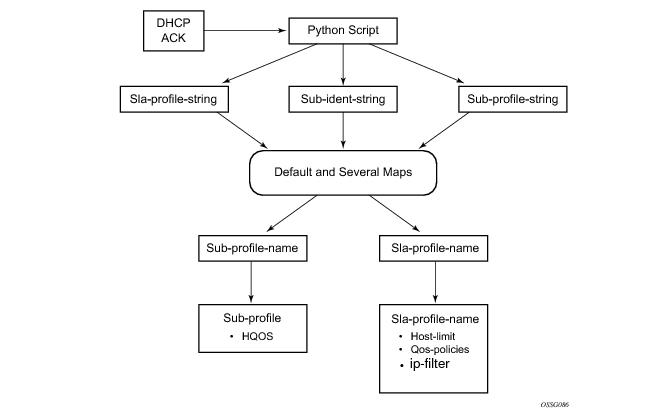
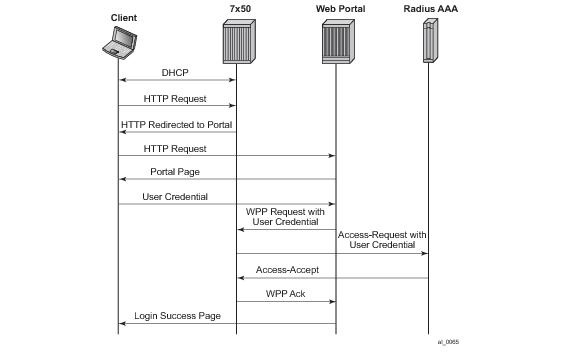
Figure 56 shows a flow of RADIUS authentication of DHCP hosts in the triple play aggregation environment. Besides granting the authentication of given DHCP host, the RADIUS server can include RADIUS attributes (standard and/or Vendor-Specific Attributes (VSAs)) which are then used by the network element to provision objects related to a given DHCP host.
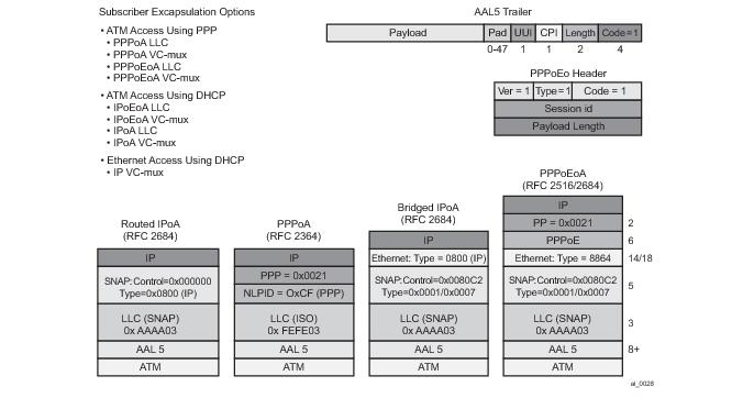
In order to comply with RFC 4679, DSL Forum Vendor-Specific RADIUS Attributes, the software includes the following attributes in the authentication-request message:
A calling-station-id can be configured at SAP level and can be included in the RADIUS authentication and accounting messages. This attribute is used in legacy BRAS to identify the user (typically phone number used for RAS connection). In the broadband networks this was replaced by circuit-id in Option 82. However, the Option 82 format is highly dependent on access-node vendor, which makes interpretation in management servers (such as RADIUS) troublesome. Some operators use the calling-station-id attribute as an attribute indicating the way the circuit-id should be interpreted. The calling-station-id attribute can be configured as a string which will be configured on the SAP. It can also be configured to use the
sap-id,
remote-id or
mac-address.
subscriber-mgmt
ppp-policy "ppp-policy-1" create
session-timeout 86400
exit
exit
config>router>radius-server#
config>service>vprn>radius-server#
server "coa-1" address 10.1.1.1 secret <shared-secret> hash2 create
accept-coa
exit
config>subscr-mgmt>auth-plcy#
accept-authorization-change
config>aaa#
radius-coa-port {1647|1700|1812|3799}
Table 14 summarizes the key differences between various accounting modes of operation that are supported. Interim-updates for each individual mode can be enabled/disabled via configuration (interim-updates keyword as an extension to the commands that enable three basic modes of accounting). This is denoted by the IU-Config keyword under the ‘I-U’ column in the table. The table also shows that any two combinations of the three basic models (including their variants for volume/time based accounting) can be enabled simultaneously.
In the per session accounting mode of operation the accounting message stream
1 (START/INTERIM-UPDATE/STOP) is generated per session.
configure
subscriber-mgmt
radius-accounting-policy "acct-policy-1" create
update-interval 60
update-interval-jitter absolute 600
By default, a random delay of 10% of the configured update-interval is added to the update-interval between two Accounting Interim Update messages. This jitter value can be configured with the
update-interval-jitter to an absolute value in seconds between zero and 3600. The effective maximum random delay value is the minimum value of the configured absolute jitter value and 10% of the configured
update-interval.
With the acct-on-off command configured in the radius-server-policy:
|
–
|
When the acct-on-off command is added to the radius-server-policy configuration.
|
|
–
|
When the acct-on-off command is removed from the radius-server-policy configuration.
|
configure
aaa
radius-server-policy "aaa-server-policy-1" create
acct-on-off oper-state-change
servers
router "Base"
server 1 name "server-1"
exit
exit
exit
configure
aaa
acct-on-off-group "group-1" create
description "Grouping of radius-server-policies acct-on-off"
exit
radius-server-policy "aaa-server-policy-1" create
acct-on-off oper-state-change group "group-1"
servers
router "Base"
server 1 name "server-1"
exit
exit
radius-server-policy "aaa-server-policy-2" create
acct-on-off monitor-group "group-1"
servers
router "Base"
server 1 name "server-2"
exit
exit
tools perform aaa acct-on [radius-server-policy
policy-name] [force
]
tools perform aaa acct-off [radius-server-policy
policy-name] [force
] [acct-terminate-cause
number]
# show aaa radius-server-policy "aaa-server-policy-3" acct-on-off
===============================================================================
RADIUS server policy "aaa-server-policy-3" AcctOnOff info
===============================================================================
Oper state : on
Session Id : 242FFF0000008F512A3985
Last state change : 02/24/2013 16:06:41
Trigger : startUp
Server : "server-1"
===============================================================================
# show aaa radius-server-policy "aaa-server-policy-3"
===============================================================================
RADIUS server policy "aaa-server-policy-3"
===============================================================================
Description : (Not Specified)
Acct Request script policy : script-policy-1
Auth Request script policy : script-policy-1
Accept script policy : script-policy-1
Acct-On-Off : Enabled (state Blocked)
-------------------------------------------------------------------------------
RADIUS server settings
-------------------------------------------------------------------------------
Router : "Base"
Source address : (Not Specified)
Access algorithm : direct
Retry : 3
Timeout (s) : 5
Hold down time (s) : 30
Last management change : 02/20/2013 13:32:05
===============================================================================
===============================================================================
Servers for "aaa-server-policy-3"
===============================================================================
Idx Name Address Port Oper State
Auth/Acct
-------------------------------------------------------------------------------
1 server-3 172.16.1.10 1812/1813 unknown
===============================================================================
# show aaa acct-on-off-group "group-1"
===============================================================================
Acct-On-Off-Group Information
===============================================================================
acct on off group name : group-1
- controlling Radius-Server-policy :
aaa-server-policy-1
- monitored by Radius-Serer-policy :
aaa-server-policy-2
-------------------------------------------------------------------------------
Nbr of Acct-on-off-groups displayed : 1
-------------------------------------------------------------------------------
===============================================================================
configure
aaa
radius-server-policy "aaa-server-policy-1" create
servers
router "Base"
buffering
acct-interim min 60 max 3600 lifetime 12
acct-stop min 60 max 3600 lifetime 12
exit
server 1 name "server-1"
exit
exit
exit
# clear aaa radius-server-policy policy-name msg-buffer
[acct-session-id
acct-session-id]
# show aaa radius-server-policy "aaa-server-policy-1" msg-buffer-stats
===============================================================================
RADIUS server policy "aaa-server-policy-1" message buffering stats
===============================================================================
buffering acct-interim : enabled
min interval (s) : 60
max interval (s) : 3600
lifetime (hrs) : 12
buffering acct-stop : enabled
min interval (s) : 60
max interval (s) : 3600
lifetime (hrs) : 12
Statistics
-------------------------------------------------------------------------------
Total acct-stop messages in buffer : 0
Total acct-interim messages in buffer : 5
Total acct-stop messages dropped (lifetime expired) : 0
Total acct-interim messages dropped (lifetime expired) : 0
Last buffer clear time : N/A
Last buffer statistics clear time : N/A
-------------------------------------------------------------------------------
===============================================================================
# clear aaa radius-server-policy policy-name statistics msg-buffer-only
# tools dump aaa radius-server-policy policy-name msg-buffer [session-id
acct-session-id]
# tools dump aaa radius-server-policy "aaa-server-policy-1" msg-buffer
===============================================================================
RADIUS server policy "aaa-server-policy-1" message buffering
===============================================================================
message type Acct-Session-Id remaining lifetime
-------------------------------------------------------------------------------
acct-interim 242FFF0000009A512B36FC 0d 11:58:54
acct-interim 242FFF0000009B512B36FC 0d 11:58:48
acct-interim 242FFF0000009C512B36FC 0d 11:58:30
acct-interim 242FFF0000009D512B36FC 0d 11:58:29
acct-interim 242FFF0000009E512B36FC 0d 11:59:05
-------------------------------------------------------------------------------
No. of messages in buffer: 5
===============================================================================
|
•
|
“on-request-failure” — All failure conditions between the sending of an Access-Request and the reception of an Access-Accept or Access-Reject.
|
|
•
|
“on-reject” — When an Access-Reject is received.
|
|
•
|
“on-accept-failure” — All failure conditions that appear after receiving an Access-Accept and before successful instantiation of the host or session.
|
configure
subscriber-mgmt
local-user-db "ludb-1" create
ppp
match-list username
host "default" create
auth-policy "auth-policy-1"
password ignore
acct-policy "acct-policy-1" duplicate "acct-policy-2"
no shutdown
exit
exit
no shutdown
exit
authentication-policy "auth-policy-1" create
pppoe-access-method pap-chap
include-radius-attribute
- - - snip - - -
exit
send-acct-stop-on-fail on-request-failure on-reject on-accept-failure
radius-server-policy "aaa-server-policy-1"
exit
radius-accounting-policy "acct-policy-1" create
- - - snip - - -
radius-server-policy "aaa-server-policy-1"
exit
radius-accounting-policy "acct-policy-2" create
- - - snip - - -
radius-server-policy "aaa-server-policy-2"
exit
configure
service
vpls 10 customer 1 create
sap 1/1/1:1.* capture-sap create
trigger-packet pppoe
pppoe-policy "ppp-policy-1"
pppoe-user-db "ludb-1"
exit
no shutdown
exit
ies 1000 customer 1 create
subscriber-interface "sub-int-1" create
- - - snip - - -
group-interface "group-int-1-1" create
- - - snip - - -
pppoe
policy "ppp-policy-1"
user-db "ludb-1"
no shutdown
exit
exit
exit
no shutdown
exit
In residential broadband networks numerous subscribers can be provisioned that can require significant changes on a daily basis. Manually configuring the applicable parameters for each subscriber would be prohibitive. The Alcatel-Lucent 7750 SR has been designed to support fully dynamic provisioning of access, QoS and security aspects for residential subscribers using DHCP to obtain an IP address. Enabling Enhanced Subscriber Management drastically reduces the configuration burden.
Enhanced Subscriber Management in the 7750 SR supports many vendor's access nodes and network aggregation models, including VLAN per customer, per service or per access node.
When the enhanced mode is enabled on a SAP (see Subscriber SAPs), first, the router ensures that existing configurations on the SAP do not prevent proper enhanced mode operation. If any one of the following requirements is not met, enhanced mode operation is not allowed on the SAP:
The management of all services, policies, AAA functions and configurations that relate to the concept of a subscriber. Subscriber management can be configured in a variety of ways, but it is critical that subscriber management integrates seamlessly with element and service management across the broadband infrastructure, via for instance, the Alcatel-Lucent 5750 Subscriber Services Controller (SSC). Subscriber management can also be implemented through CLI or scripted commands at the platform level, whereby a network administrator would manually configure the set of QoS, security, AAA or anti-spoofing functions that relate to a particular billable entity or subscriber. Subscriber management is typically centralized and highly integrated with the element, services and middleware management functions for streamlined management, flowthrough provisioning, and accelerated service activation, with minimized operating expenditures.
When multiple hosts are associated with the same subscriber identification string, they are considered to be host members of the same subscriber. Hosts from multiple SAPs can be members of the same subscriber, but for proper virtual scheduling to be performed all hosts of a subscriber must be active on the same IOM.
Refer to Determining the SLA Profile for information on how the SLA profile is determined for dynamic hosts.
config>service>ies>sub-if>grp-if>ipv6>rtr-adv
config>service>vprn>sub-if>grp-if>ipv6>rtr-adv
[no] dns-options
[no] include-dns - Set/reset inclusion of the RDNSS server
option 25 on this group-interface
[no] rdnss-lifetime – Maximum time the RDNSS address is valid
in this group-interface
configure subscriber-mgmt local-user-db <ludb-name> dhcp|ppp host <host-name> options6 dns-server <ip-address> [<ip-address>...(up to 4 max)]
configure service ies|vprn <svc-id> subscriber-interface <sub-int-name> ipv6 default- dns <ipv6-address> [secondary <secondary-ipv6-address>]
Note: A default IPv6 Server configuration at the group interface is a last resort IPv6 DNS info that can be used for IPoEv6 hosts (IA_NA, IA_PD and SLAAC) and PPPoEv6 hosts (IA_NA, IA_PD and SLAAC).
For example, a DHCPv6 server prefix pool contains an aggregated (configured) IPv6 prefix from which the delegated prefixes will be carved out. In Figure 58 this aggregated IPv6 prefix has length of /48. In addition, the DHCPv6 server needs to know the length of the delegated prefix (in the above case /60). These two values are marking the boundary within which a unique delegated prefix will be selected. This is represented by the purple area in
Figure 58.
Note that the “no delegated-prefix-length” command under the subscriber-interface>ipv6> hierarchy means that the DPL is set to a default-value of 64.
When the delegated-prefix-length commands under the subscriber-interface>ipv6> hierarchy is set to variable, prefixes under such subscriber-interface can have different lengths and the DPL can be configured via one of the following means:
config>service>vprn>sub-if>grp-if>ipv6>dhcp6# relay ?
config>service>ies>sub-if>grp-if>ipv6>dhcp6# relay ?
- no relay
- relay
[no] client-applications - Configure the set of DHCP6 relay server client
applications
[no] description - Description for DHCPv6 relay
[no] link-address - Configure the link address of the DHCPv6 relay messages
[no] option + Configure the DHCPv6 Relay information options
[no] server - Configure the DHCPv6 server IPv6 address
[no] shutdown - Administratively enable/disable DHCPv6 relay on this interface
[no] source-address - Configure the source IPv6 address of the DHCPv6 relay messages
|
−
|
ascii-tuple: host-name| service-id| group-interface-name| sap-id
|
Note: If IPv6 DNS parameters are returned in RADIUS AND a pool is specified then the DNS parameters are ignored. It is the DHCPv6 server that will need to reply with appropriate DNS servers.
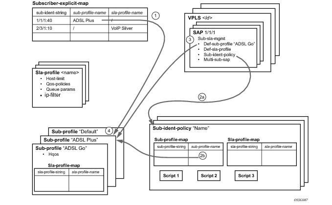
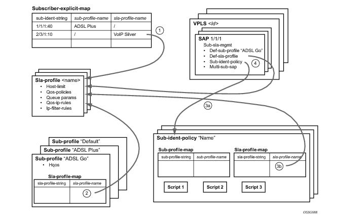
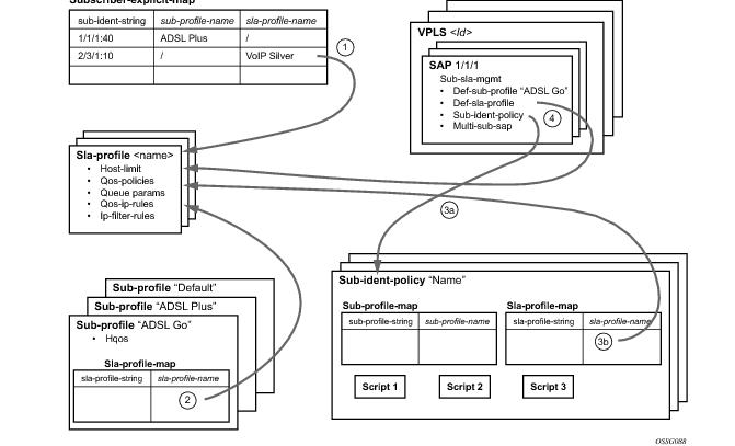
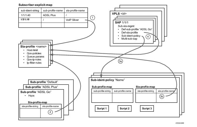
Figure 60 illustrates the relationship between the main entities in Enhanced Subscriber Management:
As depicted in Figure 61, a DSLAM is connected to an aggregation network that is connecting the DSLAM to a BRAS. ANCP is used to provide SAP level rate management. The DSLAM in this application maintains multiple ANCP connections. The primary connection is to the BRAS, providing rate and OAM capabilities while the secondary is to the router to provide rate management.
Figure 63 describes the data flow while determining which subscriber profile and SLA profile to use for a certain subscriber host based on a snooped/relayed DHCP ACK for that subscriber host.
|
1.
|
A lookup in the explicit-subscriber-map is done with the sub-ident string returned by the script. If a matching entry is found, the sub-profile-name (if defined) is taken. Otherwise:
|
|
2.
|
If a sub-ident-policy is defined on the SAP, a lookup is done on its sub-profile-map with the sub-profile string from the script. The sub-profile-name is taken from the entry. If no entry was found, then:
|
|
4.
|
The sub-profile with the name “default” is selected (if provisioned). If this is not provisioned, there are no other alternatives, the ACK is dropped, and the host will not gain access.
|
|
→
|
ppp-sub-id-key command. If no such fields are explicitly defined, the default ones will be assumed: <mac, sap-id, session-id>.
|
The use-auto-id keyword
parameter of the def-sub-id string consists of concatenated auto-sub-id-keys separated by a ‘|‘ character. In the absence of the
use-auto-id keyword, the sub-id name will be a random 10 characters encoded string based on the ipoe|ppp-sub-id-keys. This random encoded 10 character string is unique per chassis as well as in dual-homed environment.
This command will have no effect if it is configured directly under the capture SAPs in VPLS (in the config>service>vpls>sap>sub-sla-mgmt context). Managed SAPs in ESM are instantiated by a capture SAP and the msap-policy in this case is mandatory. An auto-id keyword in case of managed SAP will be looked only under the msap-policy.
If any of these limits are reached, a new host will be denied access and the DHCP ACK will be dropped. The only exception is when host-limit command is configured with the keyword
remove-oldest specified, then the oldest active host is dropped and the new host is granted access. The dynamic host with the least remaining lease time will be considered the oldest host.
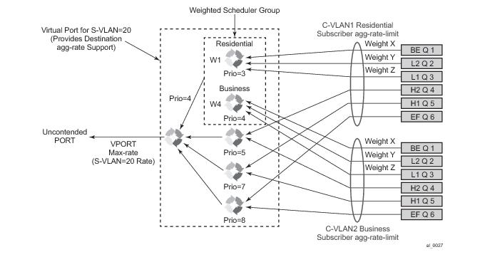
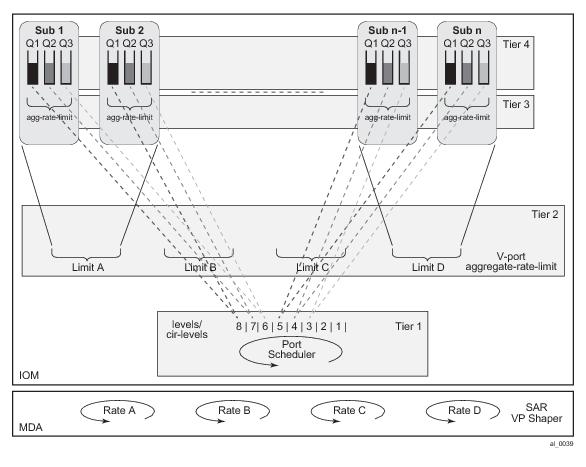
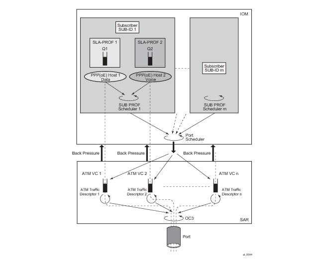
Figure 71 illustrates the queuing and scheduling model for a BNG using the Ethernet/ATM last-mile aware QoS feature.
A vport cannot be parented to the port scheduler when it is using a port scheduler policy itself. It is thus important the user ensures that the sum of the max-rate parameter value in the port scheduler policies of all vport instances on a given egress Ethernet port does not oversubscribe the port’s hardware rate. If it does, the scheduling behavior degenerates to that of the H/W scheduler on that port. A vport which uses an agg-rate-limit can be parented to a port scheduler. This is explained in Section Applying Aggregate Rate Limit to a VPORT.
|
Values
|
pppoa-llc, pppoa-null, pppoeoa-llc, pppoeoa-llc-fcs, pppoeoa-llc-tagged, pppoeoa-llc-tagged-fcs, pppoeoa-null, pppoeoa-null-fcs, pppoeoa-null-tagged, pppoeoa-null-tagged-fcs
ipoa-llc, ipoa-null, ipoeoa-llc, ipoeoa-llc-fcs, ipoeoa-llc-tagged, ipoeoa-llc-tagged-fcs, ipoeoa-null, ipoeoa-null-fcs, ipoeoa-null-tagged, ipoeoa-null-tagged-fcs,
pppoe, pppoe-tagged,
ipoe, ipoe-tagged
|
where sub-policy-agg-rate is either the value configured in the
agg-rate-limit parameter in the subscriber profile or the resulting RADIUS override value. In both cases, the CPM uses an internal override to download the adjusted value to IOM.
The value of sub-oper-agg-rate is stored in the IOM's subscriber table.
|
2.
|
If the user changes the value of the avg-frame-size parameter, enables/disables the encap-offset option, or changes the parameter value of the encap-offset option, the CPM will immediately trigger a re-evaluation of subscribers using the corresponding subscriber profile and an update the IOM with the new subscriber aggregate rate.
|
|
3.
|
If the user changes the value of the agg-rate-limit parameter in a subscriber profile which has the avg-frame-size configured, this will immediately trigger a re-evaluation of subscribers using the corresponding subscriber profile. An update to the subscriber aggregate rate is performed for those subscribers which rate has not been previously overridden by RADIUS.
|
|
4.
|
If the user changes the type value of the encap-offset command, this will immediately trigger a re-evaluation of subscribers using the corresponding subscriber profile. An update to the subscriber aggregate rate is performed for those subscribers which are currently using the default value.
|
|
1.
|
The avg-frame-size parameter in the subscriber profile is ignored.
|
|
3.
|
If the user enables/disables the encap-offset option, or changes the parameter value of the encap-offset option, the CPM will immediately trigger a re-evaluation of subscribers hosts using the corresponding subscriber profile and an update the IOM with the new fixed offset value.
|
The encap-offset option forces all the rates to be either last-mile frame over the wire or local port frame over the wire, referred to as
LM-FoW and
FoW respectively. The system maintains a running average frame expansion ratio for each queue to convert queue rates between these two formats as explained in
Frame Size, Rates, and Running Average Frame Expansion Ratio. Here are the details of the queue and scheduler operation:
|
1.
|
When the encap-offset option is configured in the subscriber profile, the subscriber host queue rates, that is, CLI and operational PIR and CIR as well as queue bucket updates, the queue statistics, that is, forwarded, dropped, and HQoS offered counters use the LM-FoW format. The scheduler policy CLI and operational rates also use LM-FoW format. The port scheduler max-rate and the priority level rates and weights, if a Weighted Scheduler Group is used, are always entered in CLI and interpreted as FoW rates. The same is true for an agg-rate-limit applied to a vport. Finally the subscriber agg-rate-limit is entered in CLI as LM-FoW rate. When converting between LM-FoW and FoW rates, the queue running average frame expansion ratio value is used.
|
|
−
|
If the user enabled frame-based-accounting in a scheduler policy or queue-frame-based-accounting with subscriber agg-rate-limit and a port scheduler policy, the queue operational rate will be capped to a user configured FoW rate. The scheduler policy operational rates will also be in the FoW format. Note that a user configured queue avg-frame-overhead value is ignored since the running average frame expansion ratio is what is used when the encap-offset option is enabled.
|
|
2.
|
When no encap-offset is configured in the subscriber profile, that is, default and pre-R9.0 behavior, queue CLI and operational PIR and CIR rates, as well as queue bucket updates, the queue statistics, use data format. The scheduler policy CLI and operational rates also use data format. The port scheduler max-rate and the priority level rates and weights, if a Weighted Scheduler Group is used, and the subscriber agg-rate-limit are entered in CLI and interpreted as FoW rates. When converting between FoW and data rates, the queue a vg-frame-overhead value is used and since this an Ethernet port, it is not user-configurable but constant and is equal to +20 bytes (IFG and preamble).
|
|
−
|
If the user enabled frame-based-accounting in a scheduler policy or queue-frame-based-accounting with subscriber agg-rate-limit and a port scheduler policy, the queue operational rate will be capped to a user configured FoW rate in CLI which is then converted into a data rate using the queue avg-frame-overhead constant value of +20 bytes. The scheduler policy operational rates will also be in the FoW format.
|
|
−
|
If the user configured queue packet-byte-offset value, it adjusts the immediate packet size. This means that the queue rates, that is, operational PIR and CIR, and queue bucket updates use the adjusted packet size. In addition, the queue statistics will also reflect the adjusted packet size. Scheduler policy rates, which are data rates, will use the adjusted packet size. The port scheduler max-rate and the priority level rates and weights, if a Weighted Scheduler Group is used, as well as the subscriber agg-rate-limit are always FoW rates and thus use the actual frame size
|
When a frame arrives at the queue, it size will be ImmediateEgressEncap+Data. This size is stored as the
OfferedFrameSize so that the queue offered stats used in HQoS calculations are correct. Let us refer to the HQoS offered statistics as Offered.
This size is then adjusted by removing the ImmediateEgressEncap and adding the
LastMileFrameOverWireEncap. This new adjusted frame size, let us refer to it as
LastMileOfferedFrameSize, is then used for checking compliance of the frame against the queue PIR and CIR bucket sizes and for updating the queue forwarded and dropped stats.
The LastMileOfferedFrameSize value is computed dynamically for each packet serviced by the queue.
A new HQoS stat counter OfferedLastMileAdjusted is maintained for the purpose of calculating the running average frame expansion ratio, which is the ratio of the accumulated
OfferedLastMileAdjusted and Offered of each queue:
The vport/port port scheduler will hand out its FoW bandwidth in terms of Fair Information Rate (FIR) bandwidth to each subscriber queue. This queue FIR must be converted into
LM-FoW format to cap it by the queue PIR (
adminPIR) and to make sure the sum of
FIRs of all queues of the same subscriber does not exceed the subscriber
agg-rate-limit which is also expressed in
LM-FoW format. The conversion between these two rates makes use of the cumulative
RunningAverageFrameExpansionRatio value.
Note that a queue LM-foW AdminPIR value will always be capped to the value of the local port
FoW rate even if the conversion based on the current
RunningAverageFrameExpansionRatio value indicates that a higher AdminPIR may be able to fill in the full line rate of the local port.
The BNG determines the parent vport of a subscriber host queue, which has the port-parent option enabled, by matching the destination string
dest string associated with the subscriber with the string defined under a vport on the port associated with the subscriber.
If a given subscriber host queue does not have the port-parent option enabled, it will be foster-parented to the vport used by this subscriber and which is based on matching the
dest string. If the subscriber could not be matched with a vport on the egress port, the host queue will not be bandwidth controlled and will compete for bandwidth directly based on its own PIR and CIR parameters.
By default, a subscriber host queue with the port-parent option enabled is scheduled within the context of the port’s port scheduler policy. In order to indicate the option to schedule the queue in the context of a port scheduler policy associated with a vport, the user enters the following command in SLA profile used by the subscriber host:
This command is persistent meaning that the user can re-enter the qos node without specifying the
vport-scheduler argument each time and the system will remember it. The user can revert to the default setting without deleting the association of the SLA profile with the SAP egress QoS policy by explicitly re-entering the command with the following new argument:
This model allows the user to oversubscribe the Ethernet port. The application of the agg-rate-limit option is mutually exclusive with the application of a port scheduler policy to a vport.
When using this model, a subscriber host queue with the port-parent option enabled is scheduled within the context of the port’s port scheduler policy. However, the user must still indicate to the system that the queues are managed by the aggregate rate limit instance of a vport by enabling the
vport-scheduler option in the subscriber host SLA profile:
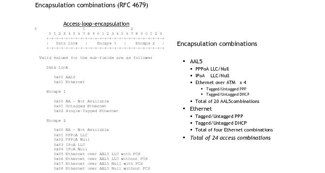
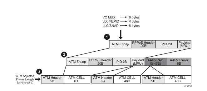
A subscriber host session can signal one of many encapsulation types each with a different fixed offset in the last mile. These encapsulation types are described in RFC 4679 and are illustrated in Figure 72 and
Figure 73. The BNG node learns the encapsulation type of each subscriber host session by inspecting the Access-loop-encapsulation sub-TLV in the Vendor-Specific PPPoE Tags as specified in RFC 4679.When Ethernet is the last mile, the encapsulation type will result in a fixed offset for all packet sizes. When ATM/DSL is the last mile, there will be an additional expansion due to AAL5 padding to next multiple of 48 bytes and which varies depending on the packet size.
*A:Dut-C# /show service active-subscribers ale-adjust
===============================================================================
Active Subscriber Access Loop Encapsulation adjustment ===============================================================================
Subscriber
SAP SLA profile
Data-link Offset(bytes)
-------------------------------------------------------------------------------
hpolSub81
1/1/11:2000.1 hpolSlaProf1
atm -10
-------------------------------------------------------------------------------
No. of Access Loop Encapsulation adjustments: 1 ===============================================================================
*A:Dut-C# show qos scheduler-hierarchy subscriber "hpolSub81"
===============================================================================
Scheduler Hierarchy - Subscriber hpolSub81 ===============================================================================
Ingress Scheduler Policy:
Egress Scheduler Policy :
-------------------------------------------------------------------------------
Root (Ing)
|
No Active Members Found on slot 1
Root (Egr)
| slot(1)
|--(Q) : Sub=hpolSub81:hpolSlaProf1 2000->1/1/11:2000.1->8->ATM (Port 1/1/11)
|
|--(Q) : Sub=hpolSub81:hpolSlaProf1 2000->1/1/11:2000.1->7->ATM (Port 1/1/11)
|
|--(Q) : Sub=hpolSub81:hpolSlaProf1 2000->1/1/11:2000.1->6->ATM (Port 1/1/11)
|
|--(Q) : Sub=hpolSub81:hpolSlaProf1 2000->1/1/11:2000.1->5->ATM (Port 1/1/11)
|
|--(Q) : Sub=hpolSub81:hpolSlaProf1 2000->1/1/11:2000.1->4->ATM (Port 1/1/11)
|
|--(Q) : Sub=hpolSub81:hpolSlaProf1 2000->1/1/11:2000.1->3->ATM (Port 1/1/11)
|
|--(Q) : Sub=hpolSub81:hpolSlaProf1 2000->1/1/11:2000.1->2->ATM (Port 1/1/11)
|
|--(Q) : Sub=hpolSub81:hpolSlaProf1 2000->1/1/11:2000.1->1->ATM (Port 1/1/11)
|
*A:Dut-C# show service active-subscribers ale-adjust
===============================================================================
Active Subscriber Access Loop Encapsulation adjustment ===============================================================================
Subscriber
SAP SLA profile
Data-link Offset(bytes)
-------------------------------------------------------------------------------
hpolSub81
1/1/11:2000.1 hpolSlaProf1
other +12
-------------------------------------------------------------------------------
No. of Access Loop Encapsulation adjustments: 1 ===============================================================================
*A:Dut-C# show qos scheduler-hierarchy subscriber "hpolSub81"
===============================================================================
Scheduler Hierarchy - Subscriber hpolSub81 ===============================================================================
Ingress Scheduler Policy:
Egress Scheduler Policy :
-------------------------------------------------------------------------------
Root (Ing)
|
No Active Members Found on slot 1
Root (Egr)
| slot(1)
|--(Q) : Sub=hpolSub81:hpolSlaProf1 2000->1/1/11:2000.1->8->Eth (Port 1/1/11)
|
|--(Q) : Sub=hpolSub81:hpolSlaProf1 2000->1/1/11:2000.1->7->Eth (Port 1/1/11)
|
|--(Q) : Sub=hpolSub81:hpolSlaProf1 2000->1/1/11:2000.1->6->Eth (Port 1/1/11)
|
|--(Q) : Sub=hpolSub81:hpolSlaProf1 2000->1/1/11:2000.1->5->Eth (Port 1/1/11)
|
|--(Q) : Sub=hpolSub81:hpolSlaProf1 2000->1/1/11:2000.1->4->Eth (Port 1/1/11)
|
|--(Q) : Sub=hpolSub81:hpolSlaProf1 2000->1/1/11:2000.1->3->Eth (Port 1/1/11)
|
|--(Q) : Sub=hpolSub81:hpolSlaProf1 2000->1/1/11:2000.1->2->Eth (Port 1/1/11)
|
|--(Q) : Sub=hpolSub81:hpolSlaProf1 2000->1/1/11:2000.1->1->Eth (Port 1/1/11)
|
*A:Dut-C# show service active-subscribers ale-adjust subscriber "hpolSub321"
===============================================================================
Active Subscriber Access Loop Encapsulation adjustment ===============================================================================
Subscriber
SAP SLA profile
Data-link Offset(bytes)
-------------------------------------------------------------------------------
hpolSub321
5/1/1:100/1 hpolSlaProf1
atm +8
-------------------------------------------------------------------------------
No. of Access Loop Encapsulation adjustments: 1 ===============================================================================
*A:Dut-C# show qos scheduler-hierarchy subscriber "hpolSub321"
===============================================================================
Scheduler Hierarchy - Subscriber hpolSub321 ===============================================================================
Ingress Scheduler Policy:
Egress Scheduler Policy :
-------------------------------------------------------------------------------
Root (Ing)
|
No Active Members Found on slot 5
Root (Egr)
| slot(5)
|--(Q) : Sub=hpolSub321:hpolSlaProf1 2000->5/1/1:100/1->8:ATM (Port 5/1/1)
|
|--(Q) : Sub=hpolSub321:hpolSlaProf1 2000->5/1/1:100/1->7:ATM (Port 5/1/1)
|
|--(Q) : Sub=hpolSub321:hpolSlaProf1 2000->5/1/1:100/1->6:ATM (Port 5/1/1)
|
|--(Q) : Sub=hpolSub321:hpolSlaProf1 2000->5/1/1:100/1->5:ATM (Port 5/1/1)
|
|--(Q) : Sub=hpolSub321:hpolSlaProf1 2000->5/1/1:100/1->4:ATM (Port 5/1/1)
|
|--(Q) : Sub=hpolSub321:hpolSlaProf1 2000->5/1/1:100/1->3:ATM (Port 5/1/1)
|
|--(Q) : Sub=hpolSub321:hpolSlaProf1 2000->5/1/1:100/1->2:ATM (Port 5/1/1)
|
|--(Q) : Sub=hpolSub321:hpolSlaProf1 2000->5/1/1:100/1->1:ATM (Port 5/1/1)
|
===============================================================================
config
qos
port-scheduler-policy "dslam-vport-scheduler"
group res-bus-be create
rate 1000
level 3 rate 1000 group res-bus-be weight w1
level 4 rate 1000 group res-bus-be weight w4
level 5 rate 1000 cir-rate 100
level 7 rate 5000 cir-rate 5000
level 8 rate 500 cir-rate 500
max-rate 5000
sap-egress 100 // residential policy
queue 1 // be-res
port-parent weight x level 3
queue 2 // l2-res
port-parent weight y level 3
queue 3 // l1-res
port-parent weight z level 3
queue 4 // h2-res
port-parent level 5
queue 5 // h1-res
port-parent level 7
queue 6 // ef-res
port-parent level 8
fc be queue 1
fc l2 queue 2
fc l1 queue 3
fc h2 queue 4
fc h1 queue 5
fc ef queue 6
exit
sap-egress 200 // business policy
queue 1 // be-bus
port-parent weight x level 4
queue 2 // l2-bus
port-parent weight y level 4
queue 3 // l1-bus
port-parent weight z level 4
queue 4 // h2-bus
port-parent level 5
queue 5 // h1-bus
port-parent level 7
queue 6 // ef-bus
port-parent level 8
fc be queue 1
fc l2 queue 2
fc l1 queue 3
fc h2 queue 4
fc h1 queue 5
fc ef queue 6
exit
exit
config
sub-mgmt
sla-profile "residential"
egress
qos 100 vport-scheduler
exit
exit
sla-profile "business"
egress
qos 200 vport-scheduler
exit
exit
sub-profile "residential"
egress
encap-offset
avg-frame-size 1500
agg-rate-limit 100
exit
exit
exit
sub-profile "business"
egress
encap-offset type pppoeoa-llc-tagged-fcs
avg-frame-size 500
agg-rate-limit 200
exit
exit
exit
exit
config
port 1/1/1
ethernet
access
egress
vport "dslam-1" create
port-scheduler-policy "dslam-vport-scheduler"
host-match dest “20” create
exit
exit
exit
exit
exit
exit
exit
# show filter ip <ip-filter-id> type <entry-type>
# show filter ipv6 <ipv6-filter-id> type <entry-type>
<entry-type> : fixed|radius-insert|credit-control-insert
# show service active-subscribers filter [subscriber <sub-ident-string>] [origin <origin>]
<sub-ident-string> : [32 chars max]
<origin> : radius|credit-control
- no shared-radius-filter-wmark
The format for [92] Nas-Filter-Rule and [26-6527-158] Alc-Nas-Filter-Rule-Shared is a string formatted as: “action direction protocol from
source to
destination options”. Refer to the table below for details on the respective fields.
entry-type : fixed | radius-insert | credit-control-insert | radius-shared
origin : radius | credit-control”
The ppp keyword in the
aal5nlpid-ppp command is used to indicate that ppp is the only encapsulation that currently supported in NLPID.
aal5mux-bridged-eth-nofcs tells each end of the VC in advance that the payload inside of the AAL5 frame is an Ethernet frame. In this case, it accepts the frame and treat it as an Ethernet frame inside AAL5. The EtherType within the frame must be set to 0x8863 (PPPoE Discovey Phase) or 0x8864 (PPPoE Session Phase).
There is a 0-2Byte additional padding (optional) in the SNAP Bridged encapsulation header that is not shown in Figure 82. This padding, according to RFC 2684, is necessary to align the info field (payload of the Layer 2 encapsulated frame) on a 4-Byte boundary.
Note: ATM concatenation mode for Apipe is not supported in the 16K VC mode.
configure
service apipe <id> [vc-type <cell-type>]
spoke-sdp <sdp:pw> cell-concatenation
[no] aal5-frame-aware
[no] clp-change
[no] max-cells
[no] max-delay
Scheduling at the ATM layer is shown in Figure 83. Shaped CBR and VBR traffic classes have two queues, an HP and an LP queue. Packets from IOM are marked according to scheduling priority of the Forwarding Class (expedited or best-effort) from which they were sent and are accepted into the ATM VC queue (HP | LP) accordingly. For example, at the IOM level packets from an expedited FC (queue) are marked as HP, and the packets from a best-effort FC (queue) are marked as LP. When these packets arrive to MDA, they will be admitted into appropriate queues, pending VC (or port) buffer availability.
configure
services ies/vprn
subscriber-interface <sub-if-name>
group-interface <grp-if-name>
sap <sap-id>
atm
ingress
traffic-desc <id>
egress
traffic-desc <id>
con figure
subscriber-management
msap-policy <name>
atm
ingress
traffic-desc <id>
egress
traffic-desc <id>
config
port <port-id>
sonet-sdh
path
atm
vp <vpi> egress-traffic-desc <atm-td-profile-id>
configure
qos
atm-td-profile <td-profile-id> [create]
weight <weight>
<weight> : 1-255.
config
port <port-id>
sonet-sdh
path
egress-scheduler-policy <port-scheduler-policy-name>
access
egress
vport <vport-name>
description <description-string>
host-match dest <dest-string>
agg-rate-limit <agg-rate>
port-scheduler-policy <port-scheduler-policy-name>
atm
vp <vpi> egress-traffic-desc <atm-td-profile-id>
configure
subscriber-mgmt
msap-policy <name>
sub-sla-mgmt
def-inter-dest-id string <inter-dest-string>
def-inter-dest-id {use-top-q | use-vpi}
configure
services ies/vprn
subscriber-interface <sub-if-name>
group-interface <grp-if-name>
sap <sap-id>
sub-sla-mgmt
def-inter-dest-id string <inter-dest-string>
def-inter-dest-id {use-top-q | use-vpi}
The def-inter-dest-id stand for a ‘default inter-destination identifier’.
|
1.
|
The encap-offset command in the sub-profile is configured. This command overwrites any other command related to rate conversion that might be configured ( frame-based-accounting, queue-frame-based-accounting, avg-frame-overhead, or avg-frame-size). The encap-offset command forces dynamic wire rates calculation in the intermediate mile (directly connected ports) on all levels in the QoS hierarchy. The wire overhead in the intermediate mile takes into account the length of the fixed ATM encapsulation, the variable length of AAL5 encapsulation (including AAL5 48bit boundary padding) and the ATM cellification overhead. The queue stats are also wire based. All calculations are performed in the data plane using the actual packet size. In other words, this command will ensure that the rates on the queue level and the subscriber aggregate level (either through virtual schedulers or egress aggregate-rate limits) are wire based. Port-scheduler and V-port rates are already by default wire based rates and this cannot be changed.
|
|
2.
|
The encap-offset command is not configured by default. In this case the other rate conversion related commands are in effect ( frame-based-accounting, queue-frame-based-accounting, avg-frame-overhead, or avg-frame-size). The behavior is the following:
|
|
–
|
agg-rate-limit (subscriber or vport) rates are always wire rates (as defined in the first bullet – based on the avg-frame-overhead).
|
|
–
|
Rates in the port-scheduler-policy (vport or physical port) are always wire based (rates (as defined in the first bullet – based on the avg-frame-overhead).
|
|
–
|
The frame-based-accounting command under the scheduler-policy will affect rate calculation for virtual schedulers and queues:
|
|
→
|
queue-frame-based-accounting configuration option under the subscriber agg-rate-limit command (in sub-profile) will affect rate calculations for queues. If this command is configured, the queue rates will be wire rates, otherwise they will be data rates
|
Currently queue rates and subscriber virtual scheduler rates are allowed to be either data rates (one in Figure 89) or
on-the-wire-rates (three in
Figure 89).
Port-scheduler rates, vport rates and the subscriber
agg-rate-limit (in sub-profile) are always on
on-the-wire rates.
configure
service ies/vprn
subscriber-interface <sub-if-name>
group-interface <grp-if-name>
dhcp
server <ip-address>
client-application pppoe => make PPPoE session the client of DHCP server
local-dhcp-server <dhcp-server-name>
user-db <ludb-name> => allow DHCP server to query LUDB
subscriber-management
local-user-db <ludb-name>
pppoe
host <host-name>
host-identification [circuit-id | mac | remote-id | service-name | username]
options
address
identification-strings
configure
service vpls <id>
sap <sap-id> capture-sap
pppoe-user-db <ludb-name>
ppp-user-db <ludb-name>
sap x/y/z:* capture-sap
atm
encapsulation aal5auto | aal5mux-ppp | aal5nlpid-ppp | aal5mux-pppoe | aal5snap-bridged-eth-nofcs
sap x/y/z:w/z
atm
encapsulation aal5auto | aal5mux-ppp | aal5nlpid-ppp | aal5mux-pppoe | aal5snap-bridged-eth-nofcs
configure
service vpls <id> customer <customer-id> [create]
sap x/y/x:*/* capture-sap [create]
atm
vc-range <num> vpi-range <vpi-range> vci-range <vci-range>
Differences in operation between PPP and PPPoE warrant creation of a new ppp node under the group-interface in the CLI that will cover PPP aspects of operation. The existing pppoe node under the
group-interface is preserved in the CLI. This allows referencing different
user-dbs for authentication purposes and different session parameters defined in the
ppp-policy for each session type (pppoe or plain ppp).
PPP node under the group-interface is used to cover PPPoA operation while PPPoE node is used to cover PPPoE and PPPoEoA operation. ATM in PPPoEoA is just a transport and as such does not carry any information relevant to PPP operation (like PADx does in PPPoE).
For dynamic SAPs (managed SAPs), the same PPP(oE) related structures are referenced under the capture SAP hierarchy. Under the capture SAP there are no ppp/pppoe nodes (like they are under the group-interface hierarchy). In order to differentiate between ppp and
pppoe clients, a new ppp-policy command is introduced in addition to the
pppoe-policy command. The
ppp-policy under the capture SAP is needed for the definition of session parameters before the
group-interface (where normally session parameters are referenced) is determined.
The ppp-policy under the
subscr-mgmt hierarchy contains PPP and PPPoE session parameters. PPP parameters are applicable to both session types (PPP and PPPoE) while PPPoE parameters are applicable only to PPPoE session type. The PPPoE parameters are ignored for PPP sessions.
configure>subscr-mgmt>ppp-policy#
ppp-mtu
configure>port>sonnet-sdh>path#
mtu
configure
service <svc-name>
subscriber-interface <sub-if-name>
group-interface <grp-if-name>
pppoe
anti-spoof [mac-sid | mac-sid-ip]
configure
service ies/vprn
subscriber-interface <sub-if-name>
group-interface <grp-if-name>
sap <sap-id>
anti-spoofing [ip|ip-mac|nh-mac]
|
•
|
ip - This option can be only used in BSM mode. This is used only for IPoE.
|
|
•
|
ip-mac – Lookup is performed based on the combination of the IP address and MAC address (incipient host). This is used for IPoE. For PPPoE, it will be overwritten by the configuration option under the group-interface-> ppp node (mac+sid or mac-sid+ip).
|
|
•
|
nh-mac – Lookup is based on the MAC only for IPoE or mac+sid for PPPoE.
|
configure
subscriber-managemnt
msap-policy <msap-pol-name>
ies-vprn-only-sap-parameters
anti-spoof [ip-mac|nh-mac]
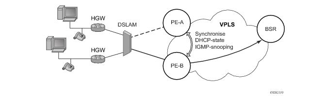
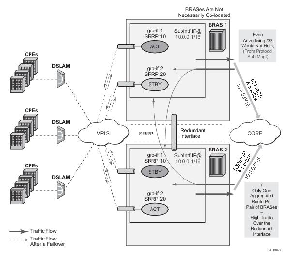
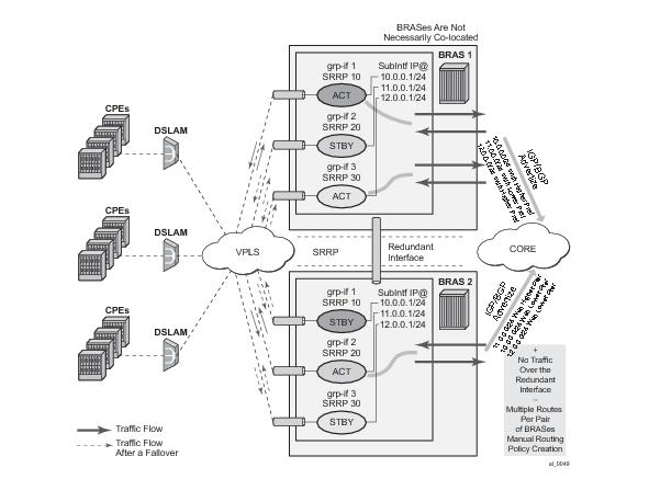
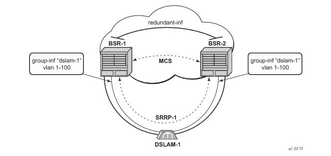
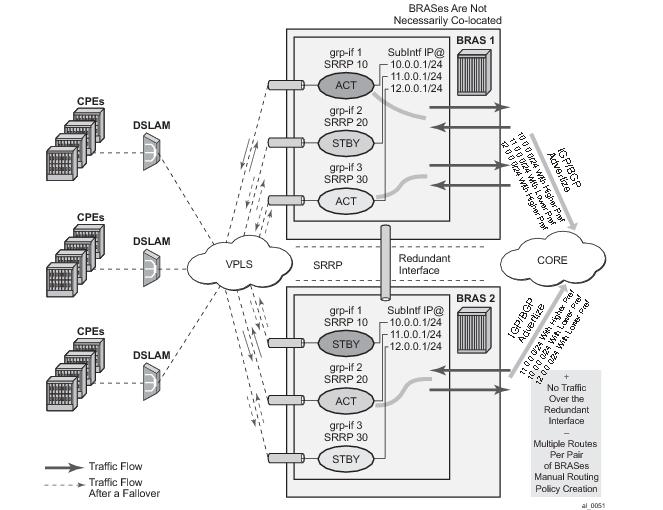
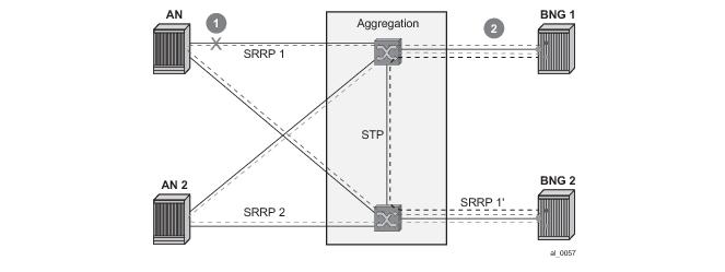
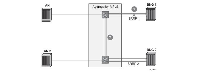
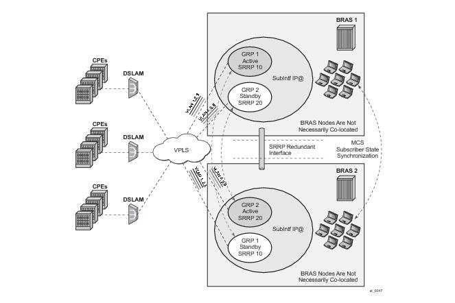
Figure 94 shows the configuration under which synchronization of subscriber management information is performed. As depicted, a single access node aggregating several subscriber lines is dual- homed to redundant-pair of nodes.
Table 15 lists the SRRP’s state effect on subscriber hosts associated with group IP interfaces.
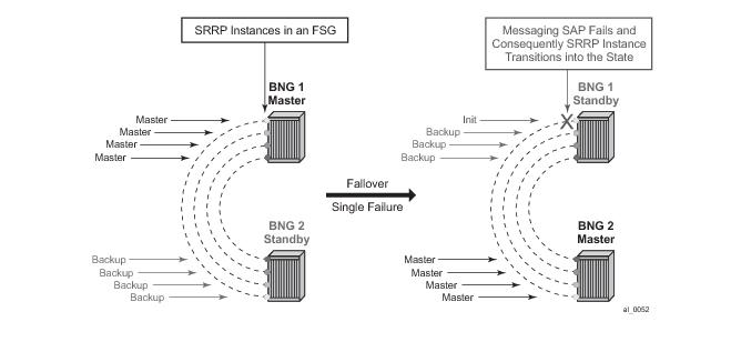
SRRP advertisement messages carry a becoming-master indicator flag. The
becoming-master flag is set by a node that is attempting to usurp the master state from an existing SRRP master router. When receiving an SRRP advertisement message with a better priority and with the
becoming-master flag set, the local master initiates its
becoming-backup state, stops routing with the SRRP gateway MAC and sends an SRRP advertisement message with a priority set to zero. The new master continues to send SRRP advertisement messages with the
becoming-master flag set until it either receives a return priority zero SRRP advertisement message from the previous master or its
becoming-master state timer expires. The new backup node continues to send zero priority SRRP advertisement messages every time it receives an SRRP advertisement message with the
becoming-master flag set. After the new master either receives the old master’s priority zero SRRP advertisement message or the
become-master state timer expires, it enters the
master state. The
become-master state timer is set to 10 seconds upon entering the
become-master state.
The SRRP instance maintains the source IP address of the current master. If an advertisement is received with the current masters source IP address and the local priority is higher priority than the masters advertised priority, the local node immediately enters the becoming-master state unless the advertised priority is zero. If the advertised priority is zero, the local node bypasses the
becoming-master state and immediately enters the
master state. Priority zero is a special case and is sent when an SRRP instance is relinquishing the master state.
In order to take full advantage of SRRP resiliency and diagnostic capabilities, the SRRP instance should be tied to a MCS peering that terminates on the redundant node. The SRRP instance is tied to the peering using the srrp srrp-id command within the appropriate MCS peering configuration. Once the peering is associated with the SRRP instance, MCS will synchronize the local information about the SRRP instance with the neighbor router. MCS automatically derives the MCS key for the SRRP instance based on the SRRP instance ID. For example, an SRRP instance ID of 1 would appear in the MCS peering database with a MCS-key srrp-0000000001.
Note: ESM v6 is supported only on IOM3 cards. IPv6 forwarding in ESM between IOM3 and IOM2 cards is not supported – for example, if the access side is IOM3 and the network side is IOM2. However, plain routing (non-ESM related) is supported between these two cards.
group-interface <name>
srrp <id>
one-garp-per-sap
multi-chassis
peer <IP@>create
sync
local-dhcp-server
SRRP
sub-mgmt [ipoe | pppoe]
:
:
no shutdown
exit
no shutdown
exit
A two keywords, ipoe and
pppoe enable a more granular control over which type of subscribers the MCS should be enabled.
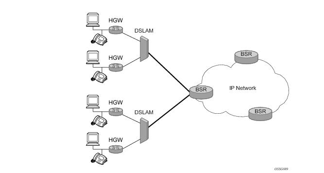
PPPoE MCS model is based on SRRP synchronization and can be used in a centralized or distributed environment with or without Layer 2 aggregation network in-between DSLAMs and BNG nodes. The failure detection speed is dependent on SRRP timers. Traffic load can be balanced per SRRP group over the two links. In this model (Figure 95), PPPoE states are synchronized between the redundant BNG nodes. If one BNG fails, the newly activated BNG sends out a ‘MAC update’ (gratuitous ARP) message prompting the intermediate Layer 2 nodes to update their forwarding tables so that forwarding can resume. The SRRP timers can be configured in the sub-second range. In reality, the limiting factor for timer values is the scale of the deployment, in particular the number of SRRP groups per node.
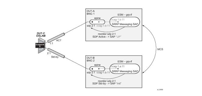
Traffic destined to/from the subscriber is forwarded under the condition that the subscriber-interface is operationally UP. This applies also to shunting of downstream subscriber traffic from the STANDBY to MASTER node. It is always necessary to keep the subscriber-interface operationally UP by configuring a dummy group-interface with a command
oper-up-while-empty under it. This is especially true for the MC-LAG which causes the messaging SAP on the STANDBY node always to be in the INIT state. In case that MSAPs are used on such group-interfaces, the group-interfaces would be also operationally DOWN, causing the subscriber-interface to be operationally DOWN.
configure>service>vpls
sap 1/1/1:1.* capture-sap
track-srrp 10
sap 1/1/1:2.* capture-sap
track-srrp 20
configure>service>vprn>
subscriber-interface <if-name>
group-interface <grp-if-name>
sap 1/1/1:1.1
srrp 10
message-path 1/1/1:1.1
group-interface <grp-if-name>
sap 1/1/1:2.1
srrp 20
message-path 1/1/1:2.1
sap port-id:*.* capture-sap
track-srrp X
configure>service>ies | vprn>
subscriber-interface <if-name>
ipv6
[no] link-local-address <ipv6-address>
<ipv6-address> : ipv6-address – x:x:x:x:x:x:x:x:x:x:x:x:x:x:d.d.d.d
x [0..FFFF]H
d [0..255]D
subscriber-interface <sub-if>
group-interface <grp-if>
dhcp
server <local-dhcp-ip-address> <remote-dhcp-ip-address>
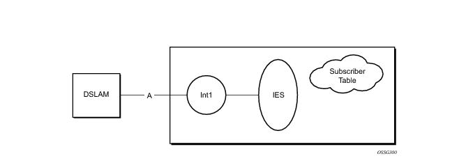
The Routed CO feature allows a network operator to connect a DSLAM to a router. Figure 98 shows a DSLAM connected to a router using a Layer 3 interface within an IES service. Operators that do not require an aggregation network can implement this topology. Typical DSLAM connection models include:
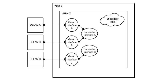
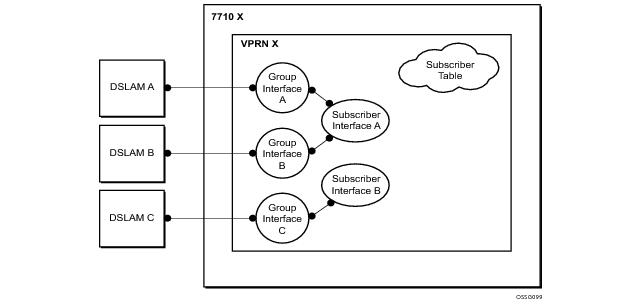
As depicted in Figure 99, an operator can create a new subscriber interface in the IES service. A subscriber interface allows for the creation of multiple group interfaces. The IP space is defined by the subnets of the subscriber interface’s addresses.
Figure 100 shows the details of group interface A.
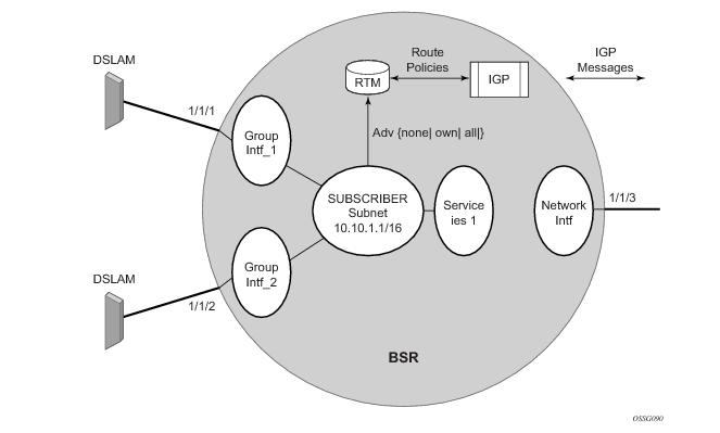
Figure 101 shows a network diagram where the DSLAM are connected directly to a Broadband Service Router (BSR) providing access to an IP subnet. Subscribers from multiple DSLAMs can be part of the same subnet. Note that BSR is referred to as BBNG, Broadband Network Gateway, in the DSL Forum.
Figure 102 shows a detailed view of a router and the configuration objects implemented to support Layer 3 subscriber interfaces.
configure
service ies/vprn <service-id>
subscriber-interface <ip-int-name>
group-interface <ip-int-name>
sap <sap-id>
anti-spoof nh-mac
configure
subscriber-mgmt
msap-policy <msap-policy-name>
ies-vprn-only-sap-parameters
anti-spoof nh-mac
config>service>ies>sub-if>grp-if>sap
config>service>vprn>sub-if>grp-if>sap
static-host ip 10.1.1.20 create
sla-profile "sla-profile-1"
sub-profile "sub-profile-1"
subscriber "static-host-1"
managed-routes
route 172.20.1.0/24
. . .
route 172.20.16.0/24
exit
no shutdown
exit
show service id service-id static-host detail
show router service-id bgp neighbor
ip-address received-routes
group "dynamic-peer-1" dynamic-peer
exit
config>subscr-mgmt
bgp-peering-policy "bgp-policy-1" create
exit
Table 16 details the RADIUS VSA attributes that can be used to setup dynamic BGP peering.
show service id service-id dhcp lease-state detail
show service id service-id dhcp6 lease-state detail
show service id service-id slaac host detail
show service id service-id ppp session detail
show service id service-id pppoe session detail
show service id service-id arp-host detail
configure
subscriber-mgmt
radius-accounting-policy <name>
include-radius-attribute
framed-route
framed-ipv6-route
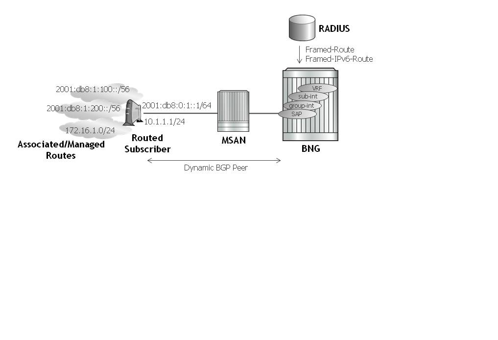
Much like the Routed CO model, the Routed CO model for VPRN depends on subscriber management to maintain the subscriber host information. To create a group-interface, the operator must first create a subscriber interface in the config>service>vprn context. The subscriber interface can maintain up to 256 subscriber subnets and can be configured with a host address for each subnet. The wholesaler subscriber interface can contain addresses that are used with its own end-customers. The host IP address can be installed as a result of both relaying to a DHCP server and proxy to a RADIUS server. In both cases the host IP address must be in the subnet defined by either the wholesaler’s or retailer’s VPRN’s subscriber interface.
The DHCP relay process has been enhanced to record incoming DHCP discover and request messages. Since forwarding to the SAPs is done by the information in the subscriber management table and multiple SAPs are allowed in one interface it was impossible to know which SAP will be used to forward the DHCP replies. The node maintains a cache of the DHCP requests. The cache can be viewed using the tools>dump>router>dhcp>group-if-mapping command. The cache holds an entry for 30 seconds. If an ACK/NAK packet was not received from the server within the timeout the node discards the cache entry. The node can use the Option 82 circuit-id field as part of the temporary host entry. If used, the ACK must contain the same circuit-id field in Option 82 to be found in the cache only if the
match-circuit-id is specified at the DHCP level of the group-interface. When the
match-circuit-id command is enabled a check is performed for option 82 circuit-id.
The routed CO model depends on subscriber management to maintain the subscriber host information. To create a group-interface the operator must first create a subscriber interface within the service (config>service>ies>subscriber-interface ip-int-name). The subscriber interface maintains up to 256 subscriber subnets and is configured with a host address for each subnet. When a DHCP ACK is received the IP address provided to the client will be verified to be in one of the subscriber subnets associated with the egress SAP. It will be noted that when DHCP snooping is enabled for regular IES interfaces the same rule will apply.
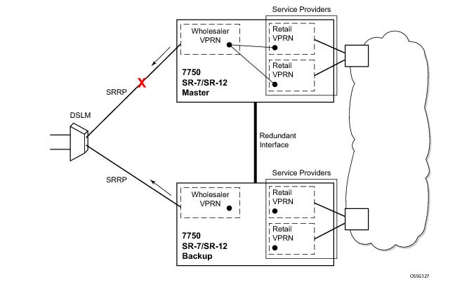
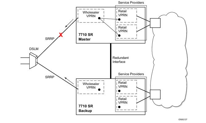
In the wholesaler/retailer model (see Figure 104), the wholesaler instance connections that are common to the access nodes are distributed to many retail instances. Upstream subscriber traffic ingresses into the wholesaler instance and after identification is then forwarded into the retail instance. The reverse will occur for traffic in the other direction. The wholesale/retail traffic flow is controlled with minimal communication with RADIUS. A RADIUS policy is defined in the wholesaler instance. The RADIUS response used during the subscriber instantiation provides the service context of the retailer VPRN. If the wholesaler has a retail business, the operator can configure a separate VPRN for their retail services.
Figure 105 shows the process starting with a DHCP DISCOVER message and, optionally, with a renew message.
Figure 106 describes the forwarding model without a “type wholesale-retail” flag. Each packet is forwarded based on the VPRN (same as the VRF) Z forwarding table. Any packet that is destined to a known subscriber host will be routed directly.
Figure 107 describes forwarding following the “type wholesale-retail” flag. Packets coming from the subscriber interface (SAP is defined in the wholesale VPRN) will be routed based on VRF Z2 routes only. Each packet coming from an LSP or Interfaces B or C will be routes based on routes from both VRF Z1 and Z2. This forwarding model is sometimes referred to as subscriber-split-horizon.
Figure 108 depicts dual-homing to two different PE nodes. The actual architecture can be based on a single DSLAM having two connections to two different PEs (using MC-LAG) or ring of DSLAMs dual-connected to redundant pair of PEs.
Figure 109 shows a typical configuration of network model based on Layer 2 CO model. Individual rings of access nodes are aggregated at BSA level in one (or multiple) VPLS services. At higher aggregation levels (the BSR), individual BSAs are connected to Layer 3 interfaces (IES or VPRN) by spoke SDP termination. Every Layer 3 interface at BSR level aggregates all subscribers in one subnet.
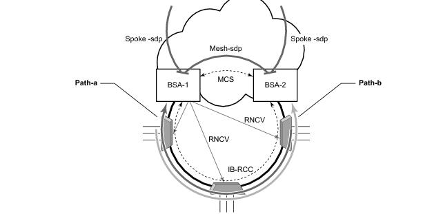
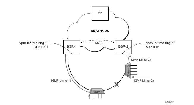
Figure 110 illustrates the operation of the dual-homed ring. The steady state is achieved when both nodes are configured in a consistent way and the peering relation is up. The multi-chassis ring must be provisioned consistently between two nodes.
In Figure 110, the ring is fully closed and every access node has two possible paths towards the VPLS core.
Figure 110 refers to these as
path-a and
path-b. In order to avoid the loop created by the ring, only one of the paths can be used by any given ring node for any given VLAN. The assignment of the individual VLANs to path-a or path-b, respectively, has to be provisioned on both BSAs.
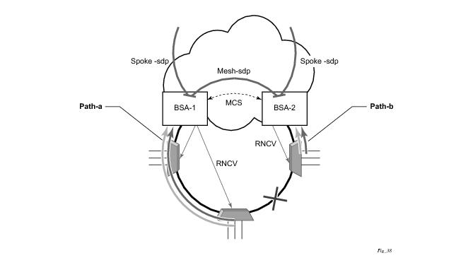
Figure 111 illustrates the model with a broken ring (link failure or ring node failure). This state is reached in following conditions:
After restoration of BFD session, the master functionality, as described in Steady-State Operation of Dual-homed Ring, is assumed by respective BSAs. The FDB tables are updated according to the master/standby role of the given BSA and FDB population messages is sent accordingly.
Figure 112 depicts a single DSLAM dual-homed to two BSRs.
|
2.
|
SRRP aware routing – this allows to dynamically increase routing metric on the IP subnets advertised from the Master SRRP node in comparison to the Standby SRRP node. It also allows to advertise/withdraw routes from a routing protocol based on the SRRP state. In this fashion, downstream traffic is routed in a predictable manner towards the Master SRRP node.
|
|
3.
|
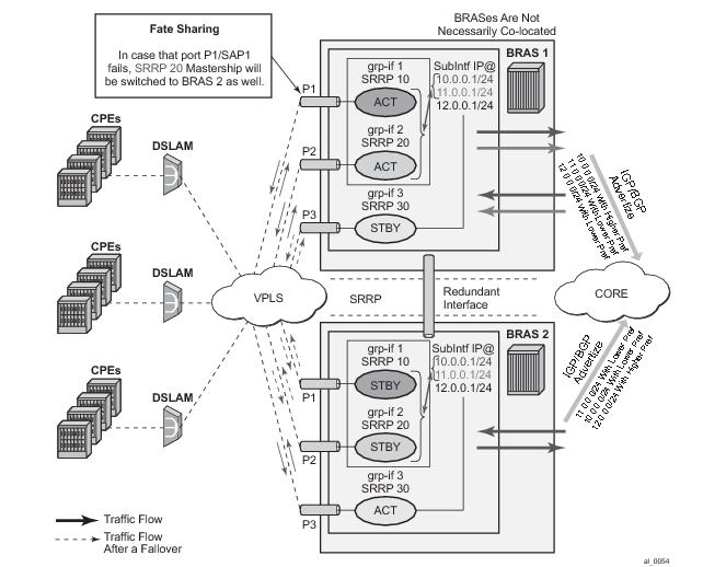
SRRP Fate Sharing for SRRP instances 10 and 11. This ensures congruency of SRRP states on the same node. This is a necessary step towards SRRP aware routing.
|
Note: The priorities will never be less than 1 or greater than initially configured SRRP priority.
subscriber-management /32 host routes that are originated through RADIUS framed-ip-address VSA other than 255.255.255.254. The 255.255.255.254 returned by the RADIUS indicates that the BNG (NAS) should assign an IP address from its own pool.
subscriber-management routes that are originated through framed-ipv6-prefix (SLAAC), delegated-ipv6-prefix (IA_PD) or alc-ipv6-address (IA_NA) RADIUS attributes . This is valid for IPoE and PPPoE type host.
subscriber-management /32 host routes that are originated via DHCP server (local or remote) and also RADIUS framed-ip-address=255.255.255.254 (RFC 2865).
subscriber-management routes that are assigned via local DHCPv6 server pools whose name is obtained through Alc-Delegated-IPv6-Pool (PD pool) and Framed-IPv6-Pool (NA pool) RADIUS attributes. This is valid for IPoE and PPPoE type hosts.
The state attribute is applied to all three route types: subscriber interface routes, managed routes and
subscriber management routes. Each route listens to the SRRP state.
Optimized routing and elimination of downstream shunt traffic during normal operation can be achieved by statically favoring the routes on the network side that are advertized with an increased metric by Master SRRP nodes.
configure
service <type> <id>
subscriber-interface <intf-name>
address <ip-address> gw-ip-address <gw-address> track-srrp <srrp-inst> holdup-time <msec>
ipv6
subscriber-prefixes
prefix <ipv6-prefix> pd track-srrp <srrp-id> holdup-time <msec>
prefix <ipv6-prefix> wan-host track-srrp <srrp-id> holdup-time <msec>
policy-options
begin
policy-statement <name>
entry 1
from
protocol direct
state ‘srrp-master’
exit
action accept
metric set 100
exit
exit
entry 2
from
protocol direct
state ‘srrp-non-master’
exit
action accept
metric subtract 10
exit
exit
entry 3
from
protocol direct
exit
action accept
exit
exit
Route Advertisement based on SRRP State requirement is applicable to BGP (IPv4, IPv4-IPVPN) and IGP.
Routing policy also provides the flexibility to prevent route advertisement (
action reject) instead of changing the route metric.
Managed routes that are tracking SRRP state are only advertised from the Master node and denied from Backup node. All other managed routes that are not tracking SRRP state are advertised regardless of the SRRP state.
policy-options
begin
policy-statement <name>
entry 1
from
protocol managed
state ‘srrp-master’
exit
action accept
exit
exit
entry 2
from
protocol managed
state ‘srrp-non-master’
exit
action reject
exit
exit
entry 3
from
protocol managed
exit
action accept
exit
exit
policy-options
begin
policy-statement <name>
entry 1
from
origin dhcp
origin aaa
state ‘srrp-master’
exit
action accept
exit
exit
exit
subscriber-interface <intf-name>
address <ip-address> gw-ip-address <gw-address> track-srrp <inst-name> holdup-time <msec>
ipv6
subscriber-prefixes
prefix <ipv6-prefix> pd track-srrp <srrp-id> holdup-time <msec>
prefix <ipv6-prefix> wan-host track-srrp <srrp-id> holdup-time <msec>
group-interface <name>
srrp-enabled-routing holdup-time <msec>
configure>service
oper-group <name> //oper-group creation
configure>service(IES | VPRN)>sub-if>grp-if>sap
oper-group <name> //adds the SAP to the oper-group
monitor-oper-group <name> // links the status of the oper-group to the SAP. In this fashion a messaging SAP can monitor the state of a PW.
configure>service(IES | VPRN)>sub-if>grp-if>srrp x
monitor-oper-group <name> priority-step [0-253] //with this, a state transition of the objects in the oper-group should trigger SRRP priority recalculation. The state of the oper-group is not important but in the state of the objects within. If an object within the oper-group goes down, the SRRP priority is lowered by a priority-step. The SRRP priority will be adjusted on every state transition of member objects.
configure>service>epipe>spoke-sdp
oper-group <name> // this will add a PW to the oper-group. A messaging SAP monitors this PW and it assumes the state according to the state of the PW in the oper-group. A standby or a DOWN PW state causes the messaging SAP to assume a DOWN state. Otherwise the messaging SAP would be in the UP state. In order for the SAP to assume the DOWN state, both RX and TX side of the PW must be shut. In other words, a PW in standby mode also must have the local TX disabled by the virtue of the ‘slave’ flag (standby-signaling-slave command under the spoke-sdp hierarchy). Without the TX disabled, the SAP monitoring the PW would not transition in the down state.
*A:Dut-C>config>service>epipe# info
----------------------------------------------
endpoint "x" create
standby-signaling-master
exit
sap 1/1/7:1 create
exit
spoke-sdp 1:1 endpoint "x" create
precedence primary
no shutdown
exit
spoke-sdp 2:1 endpoint "x" create
no shutdown
exit
no shutdown
----------------------------------------------
*A:Dut-A>config>service>epipe# info
----------------------------------------------
sap ccag-1.b:11 create
exit
spoke-sdp 2:1 create
standby-signaling-slave
oper-group "1"
no shutdown
exit
no shutdown
----------------------------------------------
*A:Dut-B>config>service>epipe# info
----------------------------------------------
sap ccag-1.b:11 create
exit
spoke-sdp 2:1 create
standby-signaling-slave
oper-group "1"
no shutdown
exit
no shutdown
----------------------------------------------
*A:Dut-A>config>service>ies# info
----------------------------------------------
redundant-interface "redif11" create
address 101.1.1.2/24 remote-ip 101.1.1.4
spoke-sdp 1:1 create
no shutdown
exit
exit
subscriber-interface "subif_1" create
shutdown
address 1.1.1.2/24 gw-ip-address 1.1.1.100
group-interface "grpif_1_2" create
shutdown
redundant-interface "redif11"
exit
exit
subscriber-interface "subTest" create
address 80.1.1.2/24 gw-ip-address 80.1.1.254
group-interface "grpTest" create
redundant-interface "redif11"
sap ccag-1.a:1 create
exit
sap ccag-1.a:11 create
monitor-oper-group "1"
exit
srrp 11 create
message-path ccag-1.a:11
no shutdown
exit
exit
exit
no shutdown
----------------------------------------------
*A:Dut-B>config>service>ies# info
----------------------------------------------
redundant-interface "redif11" create
address 101.1.1.4/24 remote-ip 101.1.1.2
spoke-sdp 1:1 create
no shutdown
exit
exit
subscriber-interface "subif_1" create
shutdown
address 1.1.1.4/24 gw-ip-address 1.1.1.100
exit
subscriber-interface "subTest" create
address 80.1.1.4/24 gw-ip-address 80.1.1.254
group-interface "grpTest" create
redundant-interface "redif11"
sap ccag-1.a:1 create
exit
sap ccag-1.a:11 create
monitor-oper-group "1"
exit
srrp 11 create
message-path ccag-1.a:11
no shutdown
exit
exit
exit
no shutdown
----------------------------------------------
*A:Dut-B>config>service>ies# show srrp
===============================================================================
SRRP Table
===============================================================================
ID Service Group Interface Admin Oper
-------------------------------------------------------------------------------
11 1 grpTest Up initialize
-------------------------------------------------------------------------------
No. of SRRP Entries: 1
===============================================================================
*A:Dut-A>config>service>ies# show srrp
*A:Dut-A>config>service>ies#
===============================================================================
SRRP Table
===============================================================================
ID Service Group Interface Admin Oper
-------------------------------------------------------------------------------
11 1 grpTest Up master
-------------------------------------------------------------------------------
No. of SRRP Entries: 1
===============================================================================
|
→
|
direction represents single character indicating i for ingress and e for egress.
|
|
→
|
type represents single character indicating q for queue, p for policer, r for aggregate-rate and a for arbiter.
|
|
→
|
key is indicated the queue or policer-id. It is not used in case of aggregate-rate and root-arbiter.
|
|
→
|
values indicates actual values preceded with keywords used in CLI (e.g., cir).
|
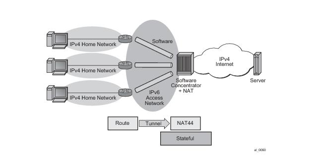
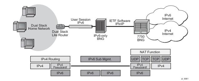
As shown in Figure 125, Dual-Stack Lite has two components, a softwire initiator in the RG and a softwire concentrator, deployed in the service provider network, where control-less IP-in-IP (using protocol 4 - IPv4 in IPv6) is used for tunnelling. When using control-less protocol, packets are sent on the wire for the remote softwire endpoint without prior setup of a tunnel.
As shown in Figure 126, IP-in-IP uses IP protocol 4 (IPv4) to encapsulate IPv4 traffic from the home network across an IPv6 access network. The IPv4 traffic tunnelling is treated as best-effort with no subscriber management or policy, and does not use ESM. The scale is dependant only on the internal structures of the MS-ISA and CPM, that is, the IP-in-IP model can support more subscribers than an ESM-based approach.
Dual-Stack Lite IP-in-IP is configured through the existing nat command that is inside the CLI statements that are within the base router or VPRN. A service performing large scale NAT supports Dual-Stack Lite.
configure {router | service vprn service-id}
- [no] nat
- inside
- [no] dual-stack-lite
- [no] *address ipv6-address
When L2TP tunnel accounting is enabled, except for host or
sla-profile-based accounting packets and attributes, the following are additional accounting packets and attributes:
Table 17 describes L2TP tunnel accounting behavior along with some key RADIUS attributes (apply for both LAC and LNS):
Table 18 lists the optional attributes that could be optionally included in tunnel accounting packet, some of them are applied for link level accounting only.
Table 18:
Optional RADIUS Attributes
|
|
|
|
|
|
|
|
|
|
|
|
|
|
|
|
|
|
|
|
All the routes downloaded will be a new protocol type “periodic”. The downloader process re-starts the AAA requests after a given interval (a configurable value but target refresh rate is 15 minutes) and routes shall be updated according to the following process:
|
•
|
Service id: service context in which the M-SAP will be created.
|
|
•
|
Interface id: name of the group-interface context in which the MSAP will be created. The group-interface must exist in the provided service for the M-SAP to be installed (routed CO scenario only).
|
|
•
|
MSAP policy: name of the policy that defines the M-SAP parameters. The policy must exist in the subscriber-mgmt context.
|
# IPoEv4 hosts
>config>service>vpls>sap# dhcp-user-db <local-user-db-name>
>config>service>ies>sub-if>grp-if>dhcp# user-db <local-user-db-name>
# PPP hosts
>config>service>vpls>sap# pppoe-user-db <local-user-db-name>
>config>service>ies>sub-if>grp-if>pppoe# user-db <local-user-db-name>
# IPoE hosts
>config>subscr-mgmt>loc-user-db>dhcp>host# auth-policy <policy-name>
# PPP hosts
>config>subscr-mgmt>loc-user-db>ppp>host# auth-policy <policy-name>
>config>subscr-mgmt>loc-user-db>dhcp>host# msap-defaults
>config>subscr-mgmt>loc-user-db>ppp>host# msap-defaults
- msap-defaults
[no] group-interface - Configure the group interface
[no] policy - Configure the MSAP policy
[no] service - Configure the service
>config>service>vpls>sap# msap-defaults ?
- msap-defaults
[no] group-interface - Configure the group interface
[no] policy - Configure the MSAP policy
[no] service - Configure the service
*A:ALA-48>config>subscr-mgmt# info
----------------------------------------------
...
category-map "triple-play" create
category "data" create
queue 1 ingress-egress
exit
category "video" create
queue 2 egress-only
exit
category "voice" create
queue 3 ingress-egress
exit
exit
category-map "aggr-subscriber-service" create
category "data-services" create
queue 1 ingress-egress
queue 3 egress-only
exit
exit
...
----------------------------------------------
*A:ALA-48>config>subscr-mgmt#
config>subscr-mgmt
category-map "idle-timeout" create
activity-threshold 25
category "cat-1" create
queue 1 ingress-egress
exit
exit
|
−
|
shcv-check — Perform a subscriber host connectivity check (IPoE hosts only). Host connectivity verification should be enabled on the corresponding group-interface for the idle-action shcv-check to take effect:
|
For PPP hosts, the idle-action shcv-check is ignored and has the same effect as “idle-action terminate”
config>subscr-mgmt
sla-profile "sla-profile-1" create
category-map "idle-timeout"
category "cat-1" create
idle-timeout 3600
idle-timeout-action terminate
exit
exit
exit
The Figure 130 illustrates high level of call flow of WPP authentication.
|
→
|
def-sub-id under sap>sub-sla-mgmt that is used for DHCP host before user is authenticated by portal server.
|
|
→
|
initial-sla-profile and initial-sub-profile that are used for the DHCP host before user is authenticated by portal server. Note: initial-sla-profile should include a ingress filter that has http-redirection entry.
|
#--------------------------------------------------
echo "Web Portal Protocol Configuration"
#--------------------------------------------------
wpp
portals
portal "portal-1" address 9.9.9.9 create
no shutdown
exit
exit
no shutdown
exit
config>service>vprn# info
---------------------------------------------------
subscriber-interface "sub-if" create
address 192.168.10.1/24
group-interface "grp-if" create
dhcp
server 1.1.1.1
gi-address 192.168.10.1
no shutdown
exit
authentication-policy "radius-auth"
sap 1/1/9 create
sub-sla-mgmt
def-sub-id "WLAN-User-Unauth"
no shutdown
exit
wpp
initial-sla-profile "webportal"
initial-sub-profile "webportal"
portal router "Base" name "portal-1"
no shutdown
exit
exit
exit
…
----------------------------------------------
A one-time-http-redirection filter could be configured in
sla-profile, this filter will be replaced by ingress filter in
sla-profile after 1st HTTP request is redirected. There is also a RADIUS VSA ( ALC-Onetime-Http-Redirection-Filter-Id) that could be included in access-accept or CoA request to override CLI configuration. The format of ALC-Onetime-Http-Redirection-Filter-Id is
Ingr-v4:filter-id; for example,
Ingr-v4:1000.
If the the filter-id is 0, then system will replace the current
one-time-http-redirection filter with ingress filter.
Note: In case of CoA, if the host’s
one-time-http-filter has already been replaced then system will just ignore the ALC-Onetime-Http-Redirection-Filter-Id.
If a 7750 SR receives filter insertion via CoA or access-accept when one-time-http-redirection filter is still active then the received filter entries will only be applied to the ingress filter. And after 1st http redirection, the update ingress filter will replace the one-time-http-redirection filter.
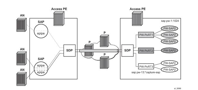
The subscriber frame encapsulated within the pseudowire is shown in Figure 133. Optional control word is not supported. The SDP could be LDP, RSVP or LDP over RSVP. Hash labels are not supported. SDP is bound to a port or a LAG. In case the SDP is re-routed, the corresponding PW-ports are operationally brought down. The PW-ports are associated with the SDP by configuration.
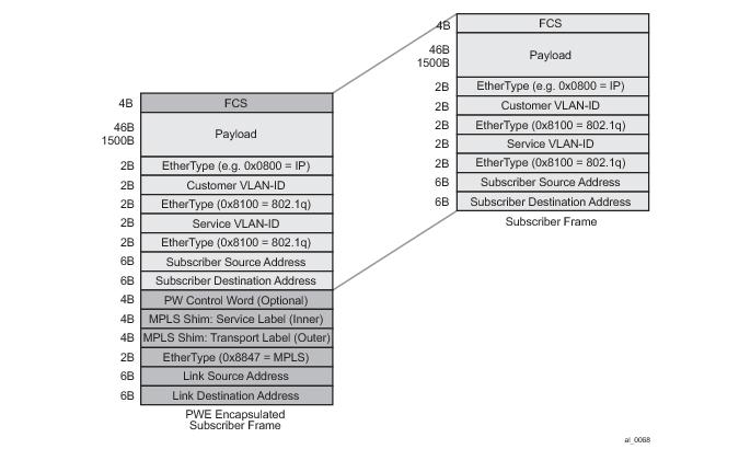
BNG requires configuration for PW-ports. The VC-label for configured PW-port is dynamically signaled using T-LDP with the far-end A-PE. The configuration for the PW-port includes the port-id (unique identifier within the chassis), vc-id (virtual circuit identifier, which is signaled to the peer), and the vc-type (Ether or VLAN, which is signaled to the peer). The vc-id and vc-type must match with the configuration of the PW on the far-end. The vc-id MUST be unique across PW-ports. The encapsulation type (dot1Q or q-in-q) on the PW-port is configurable. The default value for vc-type is Ether, and the default encapsulation type is dot1Q. With vc-type vlan, the vc-vlan-tag can be configured. vc-type vlan forwarding mode can only be set if encapsulation type is dot1Q. On the BNG, the vc-vlan-tag is only relevant for transport, and not service delineation and ESM. On the BNG, with vc-type vlan configured on the PW-port, the configured vc-type-vlan tag is inserted when forwarding traffic into the PW (i.e. in downstream direction), and top dot1Q tag is stripped when forwarding traffic out of the PW (i.e. in upstream direction). On the BNG, with vc-type ether configured on the PW-port, the received tags (max two, including any provider tag inserted by the far-end) are preserved and passed for PW-SAP lookup or creation. In the downstream direction the PW-SAP tags are inserted and passed back to the far-end.
config>service#
customer 1 create
description “Default Customer”
exit
sdp 1 mpls create
description “Default sdp description”
far-end 10.20.1.2
ldp
keep-alive
shutdown
exit
binding
port 1/1/3
pw-port 11 vc-id 11 create
vc-type vlan #### default encaps-type dot1Q
no shutdown
exit
pw-port 44 vc-id 2 create #### default vc-type Ether, encaps-type dot1Q
no shutdown
exit
exit
no shutdown
exit
vpls 1 customer 1 vpn 1 create
sap pw-11:* capture-sap create
trigger-packet arp dhcp dhcp6 pppoe #
msap-defaults
group-interface “grpif-pw-11”
policy “msap-policy1”
service 3
exit
authentication-policy “base_authpolicy”
exit
no shutdown
exit
ies 3 customer 1 vpn 3 create
description “Default ies description for sevice id 3”
subscriber-interface “subif” create
address 11.11.1.1/16
address 44.44.1.1/16
group-interface “grpif-pw-11” create
arp-populate
dhcp
server 10.20.1.2
gi-address 11.11.1.1
no shutdown
exit
authentication-policy “base_authpolicy”
sap pw-11:11 create
sub-sla-mgmt
def-sub-profile “sub_prof_1”
def-sla-profile “sla_prof_1”
no shutdown
exit
exit
exit
group-interface "grpif-pw-44" create
arp-populate
dhcp
server 10.20.1.2
gi-address 11.11.1.1
no shutdown
exit
sap pw-44:44 create
sub-sla-mgmt
def-sub-profile “sub_prof_1”
def-sla-profile “sla_prof_1”
no shutdown
exit
exit
no shutdown
exit
config>
Port 1/1/1
ethernet
mode hybrid
encap-type dot1Q
mtu 1540
access
egress
vport “v1” create
agg-rate-limit 1000
host-match dest “dslam-1” #### hosts will be associated with
exit #### vport based on inter-dest-id
exit
exit
exit
config>service>sdp>binding
pw-port 11 vc-id 11 create
egress
shaping int-dest-id “dslam-1” #### dynamic vport selection based on
#### int-dest-id.
config>
Port 1/1/2
ethernet
mode hybrid
encap-type dot1Q
access
egress
vport “v2” create
agg-rate-limit 1000
exit
exit
exit
exit
config>service>sdp>binding
pw-port 20 vc-id 20 create
egress
shaping vport “v2” #### static assignment of pw-port to vport.
exit
exit
With this feature of backhauling subscriber sessions using MPLS PW in the aggregation network, the encapsulation is shown in Fig 3. The last mile does not see any MPLS PW overhead. The next-mile includes overhead due to the PW encapsulation shown in Figure 133. Therefore, when last mile shaping is enabled, the fixed encapsulation-offset is calculated based on the difference between last-mile encapsulation type and next-mile encapsulation, The next-mile encapsulation takes into account the additional PW overhead, which includes:
config>
pw-port 2 create
exit
config>redundancy#
multi-chassis
peer 10.20.1.3 create
source-address 10.20.1.2
sync
srrp
sub-mgmt ipoe pppoe
port pw-2 sync-tag "tag2" create
exit
no shutdown
exit
no shutdown
exit
exit
exit
config>service>ies#
redundant-interface "redundant-interface" create
address 10.10.30.2/24 remote-ip 10.10.30.3
spoke-sdp 23:1000 create
no shutdown
exit
exit
config>service#
sdp 1 mpls create
far-end 10.20.1.2
ldp
keep-alive
shutdown
exit
binding
port 1/1/1
pw-port 2 vc-id 2 create
vc-type vlan #### default encaps-type dot1Q
no shutdown
exit
exit
no shutdown
exit
config>service#
subscriber-interface "subif" create
address 11.11.1.2/16 gw-ip-address 11.11.1.1 populate-host-routes
group-interface "grpif" create
authentication-policy "base_authpolicy"
redundant-interface "redundant-interface"
sap pw-2:1000 create
description "sap-grp-3"
exit
srrp 1 create
message-path pw-2:1000
no shutdown
exit
arp-host
host-limit 8000
min-auth-interval 1
no shutdown
exit
exit
exit
exit
config>
pw-port 2 create
exit
config>redundancy#
multi-chassis
peer 10.20.1.2 create
source-address 10.20.1.3
sync
srrp
sub-mgmt ipoe pppoe
port pw-2 sync-tag "tag2" create
exit
exit
no shutdown
exit
exit
exit
config>service>ies#
redundant-interface "redundant-interface" create
address 10.10.30.3/24 remote-ip 10.10.30.2
spoke-sdp 32:1000 create
no shutdown
exit
exit
config>service#
sdp 1 mpls create
far-end 10.20.1.2
ldp
keep-alive
shutdown
exit
binding
port 1/1/1
pw-port 2 vc-id 2 create
vc-type vlan #### default encaps-type dot1Q
no shutdown
exit
exit
no shutdown
exit
config>service#
subscriber-interface "subif" create
address 11.11.1.3/16 gw-ip-address 11.11.1.1 populate-host-routes
group-interface "grpif" create
authentication-policy "base_authpolicy"
redundant-interface "redundant-interface"
sap pw-2:1000 create
description "sap-grp-3"
exit
srrp 1 create
keep-alive-interval 1
message-path pw-2:1000
no shutdown
exit
arp-host
host-limit 8000
min-auth-interval 1
no shutdown
exit
exit
group-interface "dummy" create
oper-up-while-empty
exit
exit
exit
config>service>epipe#
description "Default epipe description for service id 103"
service-mtu 1492
service-name "XYZ Epipe 103"
endpoint "x" create
standby-signaling-master
exit
sap 1/1/3 create
description "Default sap description for service id 103"
exit
spoke-sdp 1:2 endpoint "x" create
description "Description for Sdp Bind 1 for Svc ID 103"
precedence primary
no shutdown
exit
spoke-sdp 2:2 endpoint "x" create
description "Description for Sdp Bind 2 for Svc ID 103"
no shutdown
exit
no shutdown
Note: With PW over ESM, redundancy in the aggregation network based on MC-LAG between A-PE and dual BNGs is not supported.
config>
pw-port 1 create
exit
config>redundancy#
multi-chassis
peer 10.20.1.2 create
source-address 10.20.1.3
sync
srrp
sub-mgmt ipoe pppoe
port pw-1 sync-tag "tag1" create
exit
exit
no shutdown
exit
exit
exit
config>service>ies
redundant-interface "red-1-1" create
address 1.1.1.2/24 remote-ip 1.1.1.1
spoke-sdp 1:1 create
no shutdown
exit
exit
subscriber-interface "sub-1-1" create
address 20.1.2.2/16 gw-ip-address 20.1.255.254 track-srrp 1
address 20.2.2.2/16 gw-ip-address 20.2.255.254 track-srrp 2
dhcp
gi-address 20.1.2.2
exit
group-interface "grp-1-1-1" create
srrp-enabled-routing
arp-populate
dhcp
server 10.20.1.2
trusted
lease-populate 32767
client-applications dhcp ppp
gi-address 20.1.2.2
no shutdown
exit
authentication-policy "iesAuthPol"
redundant-interface "red-1-1"
sap pw-1:1.1 create
sub-sla-mgmt
def-sub-profile “sub_prof_1”
def-sla-profile “sla_prof_1”
no shutdown
exit
sap pw-1:4000.1 create
oper-group "1"
exit
srrp 1 create
gw-mac 00:00:5e:00:01:01
keep-alive-interval 50
message-path pw-1:4000.1
monitor-oper-group "1" priority-step 10
no shutdown
exit
exit
config>service
customer 1 create
description "Default customer"
exit
sdp 1000 mpls create
far-end 10.20.1.2
lsp "lsp_1"
path-mtu 1600
keep-alive
no shutdown
exit
sdp 1002 mpls create
far-end 10.20.1.3
lsp "lsp_3"
path-mtu 1600
keep-alive
no shutdown
exit
vpls 1 customer 1 create
service-mtu 1600
stp
sap 1/1/2 create // to Access-Node
exit
sap 1/1/3 create; //to A-PE2
exit
spoke-sdp 1000:1 create // to BNG1
no shutdown
exit
no shutdown
exit
exit
config>service
customer 1 create
description "Default customer"
exit
sdp 1002 mpls create
far-end 10.20.1.3
lsp "lsp_2"
path-mtu 1600
keep-alive
no shutdown
exit
vpls 1 customer 1 create
service-mtu 1600
stp
sap 1/1/2 create // to Access-Node
exit
sap 1/1/3 create; //to A-PE1
exit
spoke-sdp 1002:1 create // to BNG2
no shutdown
exit
no shutdown
exit
exit
A:Dut-B>config>redundancy# show srrp 1
===============================================================================
SRRP Instance 1
===============================================================================
Description : (Not Specified)
Admin State : Up Oper State : master
Preempt : yes One GARP per SAP : no
Monitor Oper Group : None
System IP : 10.20.1.2
Service ID : VPRN 3
Group If : grpif MAC Address : 1c:85:ff:00:00:00
Grp If Description : N/A
Grp If Admin State : Up Grp If Oper State: Up
Subscriber If : subif
Sub If Admin State : Up Sub If Oper State: Up
Address : 11.11.1.2/16 Gateway IP : 11.11.1.1
Redundant If : redundant-interfa*
Red If Admin State : Up Red If Oper State: Up
Address : 10.10.30.2/24
Red Spoke-sdp : 23:1000
Msg Path SAP : pw-2:1000
Admin Gateway MAC : Oper Gateway MAC : 00:00:5e:00:01:01
Config Priority : 100 In-use Priority : 100
Master Priority : 100
Keep-alive Interval : 1 deci-seconds Master Since : 05/29/2012 07:22:26
Fib Population Mode : all
VRRP Policy 1 : None VRRP Policy 2 : None
===============================================================================
* indicates that the corresponding row element may have been truncated.
A:Dut-B>config>redundancy# show service id 3 arp-host
===============================================================================
ARP host table, service 3
===============================================================================
IP Address Mac Address Sap Id Remaining MC
Time Stdby
-------------------------------------------------------------------------------
11.11.1.11 00:80:00:00:00:01 [pw-2:11] 03h35m47s
11.11.1.12 00:80:00:00:00:02 [pw-2:12] 03h35m47s
-------------------------------------------------------------------------------
Number of ARP hosts : 2
===============================================================================
A:Dut-B>config>redundancy# show router 3 route-table 11.11.1.11
===============================================================================
Route Table (Service: 3)
===============================================================================
Dest Prefix[Flags] Type Proto Age Pref
Next Hop[Interface Name] Metric
-------------------------------------------------------------------------------
11.11.1.11/32 Remote Sub Mgmt 00h24m26s 0
[grpif] 0
-------------------------------------------------------------------------------
No. of Routes: 1
Flags: L = LFA nexthop available B = BGP backup route available
n = Number of times nexthop is repeated
===============================================================================
A:Dut-B>config>service>vprn#
A:Dut-C>config>redundancy# show srrp 1
===============================================================================
SRRP Instance 1
===============================================================================
Description : (Not Specified)
Admin State : Up Oper State : initialize
Preempt : yes One GARP per SAP : no
Monitor Oper Group : None
System IP : 10.20.1.3
Service ID : VPRN 3
Group If : grpif MAC Address : 1c:87:ff:00:00:00
Grp If Description : N/A
Grp If Admin State : Up Grp If Oper State: Down
Subscriber If : subif
Sub If Admin State : Up Sub If Oper State: Up
Address : 11.11.1.3/16 Gateway IP : 11.11.1.1
Redundant If : redundant-interfa*
Red If Admin State : Up Red If Oper State: Up
Address : 10.10.30.3/24
Red Spoke-sdp : 32:1000
Msg Path SAP : pw-2:1000
Admin Gateway MAC : Oper Gateway MAC : 00:00:5e:00:01:01
Config Priority : 1 In-use Priority : 1
Master Priority : 1
Keep-alive Interval : 1 deci-seconds Master Since : 05/29/2012 07:22:26
Master Down Interval: 0.000 sec (Expires in 0.000 sec)
Fib Population Mode : all
VRRP Policy 1 : None VRRP Policy 2 : None
===============================================================================
* indicates that the corresponding row element may have been truncated.
A:Dut-C>config>redundancy# show service id 3 arp-host
===============================================================================
ARP host table, service 3
===============================================================================
IP Address Mac Address Sap Id Remaining MC
Time Stdby
-------------------------------------------------------------------------------
11.11.1.11 00:80:00:00:00:01 [pw-2:11] 03h38m01s Yes
11.11.1.12 00:80:00:00:00:02 [pw-2:12] 03h38m02s Yes
-------------------------------------------------------------------------------
Number of ARP hosts : 2
===============================================================================
A:Dut-C>config>redundancy# show router 3 route-table 11.11.1.11
===============================================================================
Route Table (Service: 3)
===============================================================================
Dest Prefix[Flags] Type Proto Age Pref
Next Hop[Interface Name] Metric
-------------------------------------------------------------------------------
11.11.1.11/32 Remote Sub Mgmt 00h22m03s 0
[redundant-interface] 0
-------------------------------------------------------------------------------
No. of Routes: 1
Flags: L = LFA nexthop available B = BGP backup route available
n = Number of times nexthop is repeated
===============================================================================
config>subscr-mgmt
diameter-policy "diameter-1" create
diameter-base
origin-host "bng.alcatel-lucent.com"
origin-realm "alcatel-lucent.com"
source-address 10.0.0.1
connection-timer 5
peer "peer-1" create
address 10.1.0.1
destination-host "server.alcatel-lucent.com"
destination-realm "alcatel-lucent.com"
no shutdown
exit
exit
exit
config>subscr-mgmt
category-map "cat-map-1" create
credit-type time
category "cat-1" create
rating-group 1
queue 1 ingress-egress
exhausted-credit-service-level
pir 64
exit
exit
exit
credit-control-policy "cc-policy-1" create
credit-control-server diameter "diameter-1"
default-category-map "cat-map-1"
out-of-credit-action change-service-level
exit
sla-profile "sla_prof_1" create
credit-control-policy "cc-policy-1"
exit
To share a DHCP pool among BNG, the DHCP server will first require a gi-address. This feature is used in conjunction with
use-gi-address from the
local-dhcp-server and the scope should be
pool to allow allocation of all subnets within the pool. The DHCP discovery must contain any of the three vendor specific options in Option 82: service ID, service-plus-system ID, or custom string. The intent is to bind a subnet from the shared pool to one of the three required parameters from the vendor specific option (VSO).
Each subscriber interface sharing a DHCP pool, must utilize a unique gi-address. This is to ensure that the DHCP offer can correctly route back to the subscriber interface as shown in
Figure 139. The number of subscriber interfaces sharing the DHCP pool, must have at least the equivalent number of subnets in the DHCP pool. The number of subnets available for sharing should always be equal or greater then the number of subscriber interfaces.
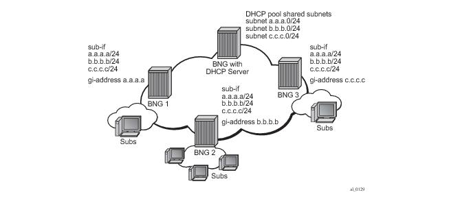
To avoid advertising the same IP subnet from multiple subscriber interfaces. A combination of router aggregation and route policies are used to ensure BNGs do not advertisement overlaps subnets. If BNG1, BNG2, and BNG N are sharing a DHCP pool with subnet A,B,C,…,Z. All BNGs must first provision the same subnets on their subscriber interfaces. These subscriber interfaces must not be included in any IGP interfaces, because that will lead to multiple BNG advertising the same subnets which is undesirable. The key is to advertise a subnet only if a subscriber has successfully allocated an address from that particular subnet. Aggregate route can be used to accomplish this. First, the aggregation route will specify a smaller (more specific) subnet of the subscriber interface. For example if Subnet A is 1.1.1.1/24 then the aggregation route would be split into the next smallest subnet 1.1.1.0/25 and 1.1.1.128/25 respectively. A Route policy is then used to advertise the two /25 into IGP only if these aggregate routes become active. A subscriber that has successfully obtained an IP address from the shared pool will activate the aggregate route in the RIB. Once activated in the RIB, the route policy exports these routes by means of IGP or BGP. This in conjunction with ODSA, allows a subnet to be shared between BNGs and provides proper routing for all subscriber traffic.
ODSA allows the option of binding a subnet to any of 3 following keys: system-id, system-id + svc-id, or string. For SRRP setups, while PPPoE only allow the use of “string”, IPoE allow the use of any of the three keys for subnet binding. Notice that first two keys both use the element “system-id” for binding. During a SRRP failover, the slave system-id takes over and the new system-id will in turn bind to new subnets. Existing subnet bounded by the old master system-id are non-accessible even if there are still free addresses available. Subscribers created before the failover still requires DHCP renews, requests, and releases of their addresses. When the DHCP server receives these, renews, requests, and releases, the gi-address and system-id might no longer match. The DHCP server will still answer these DHCP messages as long as the IP and MAC address matches the one registered on the server. This allows the subscriber to experience a seamless connection during a SRRP failover.
Configuration wise, LUDB must be referenced under the group-interface>dhcp/ppp/pppoe hierarchy (and possibly under the capture SAP), while the authentication-policy is specified within the LUDB. In this fashion, LUDB access is followed by RADIUS access. The subscriber-host parameters retrieved from both sources are combined with LUDB parameters being prioritized over RADIUS parameters in case that both sources return the same parameters.
|
1.
|
Subscriber-interface is unnumbered — For example, there is no explicit assigned IP address. Instead the subscriber-interface borrows the IP address from an existing interface that is operationally UP and is located in the same routing instance (router | vprn) 2. |
configure service ies <id>
configure service vprn <id>
subscriber-interface <intf-name>
unnumbered <ip-addr | interface-name >
configure service ies <id>
configure service vprn <id>
subscriber-interface <intf-name>
allow-unmatching-subnets
The above commands (unnumbered and
allow-unmatching-subnets) are mutually exclusive. In addition, the unnumbered command can be configured only if the subscriber-interface does not have an IP address already configured. Otherwise the execution of this command will fail.
configure service ies <id>
configure service vprn <id>
subscriber-interface <name>
ipv6
allow-unmatching-prefixes
|
−
|
allow-unmatching-subnets is configured. This command is allowed only if subscriber-interface has also configured its own IPv4 address(es). In this case the IP address for IPCP negotiation is one of the sub-intf addresses. Hosts outside of the sub-intf subnets are instantiated and forwarded.
|
|
−
|
The unnumbered < ip-address | intf> command is not allowed in this scenario.
|
|
−
|
The allow-unmatching-subnets command has no effect since subscriber-interface does not have an IPv4 address configured and is therefore operationally down. No subscribers can be instantiated.
|
|
−
|
The unnumbered < ip-address | intf> command is the only viable option in this case. The subscriber-interface borrows an IPv4 address from another interface that is operationally UP and consequently this allows subscribers to be instantiated. This command is mutually exclusive with allow-unmatching-subnets. In addition, this command can only be configured if the subscriber-interface itself does not have explicitly configured an IPv4 address.
|
|
•
|
IPoEv6 and PPPoEv6 — the allow-unmatching-prefixes command is independent of any IPv4 command related to flexible IP address assignment ( unnumbered or allow-unmatching-subnets). This command can always be enabled, regardless of the v6 prefixes configured under the subscriber-interface>ipv6 hierarchy. Any subscriber, regardless of the subscriber-interface prefix configuration will be instantiated and forwarded.
|
|
•
|
Executing the no allow-unmatching-subnets command is only allowed when there are no unnumbered DHCPv4 hosts instantiated under the subscriber-interface.
|


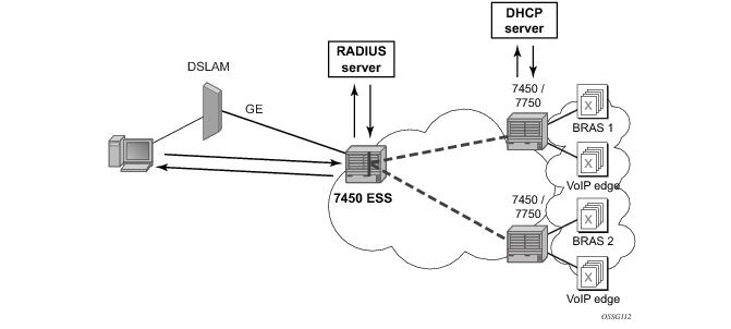 7450 ESS:
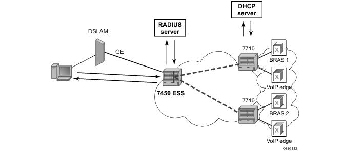 7710 SR:
 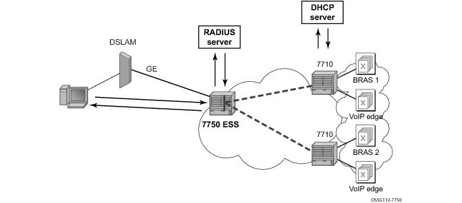 7750 SR
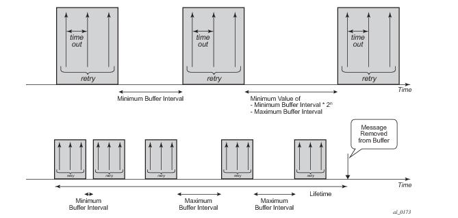
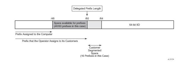
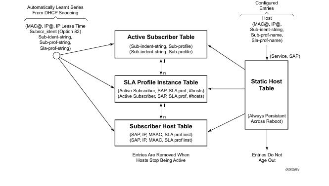
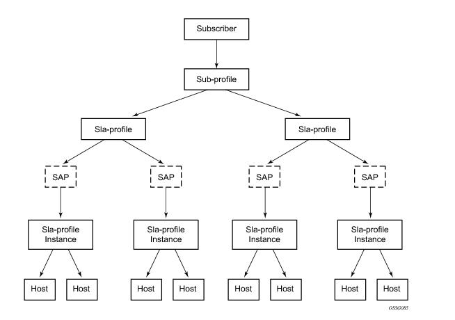
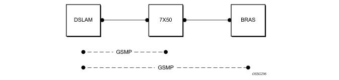 7750 SR and 7450 ESS:
 7710 SR: