oam lsp-ping bgp-label prefix ip-prefix/
mask [
src-ip-address ip-address] [
fc fc-name [
profile {
in|
out}]] [
size octets] [
ttl label-ttl] [
send-count send-count] [
timeout timeout] [
interval interval] [
path-destination ip-address [
interface if-name |
next-hop ip-address]] [
detail]
oam lsp-trace bgp-label prefix ip-prefix/
mask [
src-ip-address ip-address] [
fc fc-name [
profile {
in|
out}]] [
max-fail no-response-count] [
probe-count probes-per-hop] [
size octets] [
min-ttl min-label-ttl] [
max-ttl max-label-ttl] [
timeout timeout] [
interval interval] [
path-destination ip-address [
interface if-name |
next-hop ip-address]] [
detail]
|
1.
|
If the users initiates an lsp-trace or lsp-ping of the FEC without the path-destination option specified, then the sender node will not include multi-path information in the Downstream Mapping TLV in the echo request message (multipath type=0). In this case, the responder node will reply with a Downstream Mapping TLV for each outgoing interface which is part of the ECMP next-hop set for the FEC. Note however the sender node will select the first Downstream Mapping TLV only for the subsequent echo request message with incrementing TTL.
|
|
2.
|
If the user initiates an lsp-ping of the FEC with the path-destination option specified, then the sender node will not include the Downstream Mapping TLV. However, the user can use the interface option, part of the same path-destination option, to direct the echo request message at the sender node to be sent out a specific outgoing interface which is part of an ECMP path set for the FEC.
|
|
3.
|
If the user initiates an lsp-trace of the FEC with the path-destination option specified but configured not to include a downstream mapping TLV in the MPLS echo request message using the CLI command downstream-map-tlv { none}, then the sender node will not include the Downstream Mapping TLV. However, the user can use the interface option, part of the same path-destination option, to direct the echo request message at the sender node to be sent out a specific outgoing interface which is part of an ECMP path set for the FEC.
|
|
4.
|
If the user initiates an lsp-trace of the FEC with the path-destination option specified, then the sender node will include the multipath information in the Downstream Mapping TLV in the echo request message (multipath type=8). The path-destination option allows the user to exercise a specific path of a FEC in the presence of ECMP. This is performed by having the user enter a specific address from the 127/8 range which is then inserted in the multipath type 8 information field of the Downstream Mapping TLV. The CPM code at each LSR in the path of the target FEC runs the same hash routine as the data path and replies in the Downstream Mapping TLV with the specific outgoing interface the packet would have been forwarded to if it did not expire at this node and if DEST IP field in the packet’s header was set to the 127/8 address value inserted in the multipath type 8 information.. This hash is based on:
|
|
a.
|
The {incoming port, system interface address, label-stack} when the lsr-load-balancing option of the incoming interface is configured to lbl-only. In this case the 127/8 prefix address entered in the path-destination option is not used to select the outgoing interface. All packets received with the same label stack will map to a single and same outgoing interface.
|
|
b.
|
The {incoming port, system interface address, label-stack, SRC/DEST IP fields of the packet} when the lsr-load-balancing option of the incoming interface is configured to lbl-ip. The SRC IP field corresponds to the value entered by the user in the src-ip-address option (default system IP interface address). The DEST IP field corresponds to the 127/8 prefix address entered in the path-destination option. In this case, the CPM code will map the packet, as well as any packet in a sub-range of the entire 127/8 range, to one of the possible outgoing interface of the FEC.
|
|
c.
|
The {SRC/DEST IP fields of the packet} when the lsr-load-balancing option of the incoming interface is configured to ip-only. The SRC IP field corresponds to the value entered by the user in the src-ip-address option (default system IP interface address). The DEST IP field corresponds to the 127/8 prefix address entered in the path-destination option. In this case, the CPM code will map the packet, as well as any packet in a sub-range of the entire 127/8 range, to one of the possible outgoing interface of the FEC.
|
|
e.
|
Note that if the user enabled the system-ip-load-balancing hash option ( config>system>system-ip-load-balancing), then the LSR hashing is modified by applying the system IP interface, with differing bit-manipulation, to the hash of packets of all three options ( lbl-only, lbl-ip, ip-only). This system level option enhances the LSR packet distribution such that the probability of the same flow selecting the same ECMP interface index or LAG link index at two consecutive LSR nodes is minimized.
|
Type # Operation
------ ---------
1 Push
2 Pop
|
1.
|
An SAA test of type lsp-trace is created (not modified) and no value is specified for the per-test downstream-map-tlv { dsmap| ddmap| none} option. In this case the SAA test downstream-map-tlv value defaults to the global mpls-echo-request-downstream-map value.
|
|
2.
|
An OAM test of type lsp-trace test is executed and no value is specified for the per-test downstream-map-tlv { dsmap| ddmap| none} option. In this case, the OAM test downstream-map-tlv value defaults to the global mpls-echo-request-downstream-map value.
|
A consequence of the rules above is that a change to the value of mpls-echo-request-downstream-map option does not affect the value inserted in the downstream mapping TLV of existing tests.
|
a.
|
The user issues a LSP trace from a sender node with a min-ttl value higher than 1 and a max-ttl value lower than the number of hops to reach the egress of the target FEC stack. This is the sender node behavior when the global configuration or the per-test setting of the DSMAP/DDMAP is set to DSMAP.
|
|
6.
|
If the responder node is the egress for one or more FECs in the target FEC Stack, then it must reply with no DDMAP TLV and with a return code 3 Replying router is an egress for the FEC at stack-depth <RSC>. RSC must be set to the depth of the topmost FEC. This operation is iterative in a sense that at the receipt of the echo reply message the sender node will pop the topmost FEC from the target stack FEC TLV and resend the echo request message with the same TTL value as explained in (5) below. The responder node will thus perform exactly the same operation as described in this step until all FECs are popped or until the topmost FEC in the target FEC stack TLV matches the tunneled or stitched FEC. In the latter case, processing of the target FEC stack TLV follows again steps (1) or (2).
|
|
1.
|
If the echo reply message contains the return code 14 See DDMAP TLV for Return Code and Return Subcode and the DDMAP TLV has a return code 15 Label switched with FEC change, the sender node adjusts the target FEC Stack TLV in the echo request message for the next value of the TTL to reflect the operation on the current target FEC stack as indicated in the FEC stack change sub-TLV received in the DDMAP TLV of the last echo reply message. In other words, one FEC is popped at most and one or more FECs are pushed as indicated.
|
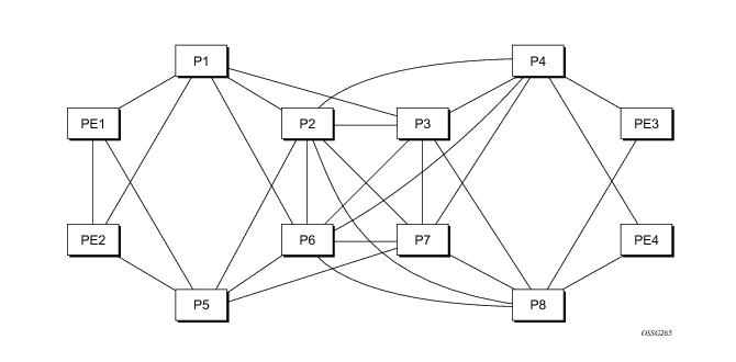
Figure 21 depicts an IP/MPLS network which uses LDP ECMP for network resilience. Faults that are detected through IGP and/or LDP are corrected as soon as IGP and LDP re-converge. The impacted traffic will be forwarded on the next available ECMP path as determined by the hash routine at the node that had a link failure.
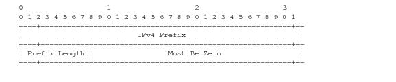
When the LDP tree trace feature is enabled, the ingress LER builds the ECM tree for a given FEC (egress LER) by sending LSP trace messages and including the LDP IPv4 Prefix FEC TLV as well as the downstream mapping TLV.In order to build the ECMP tree, the router LER inserts an IP address range drawn from the 127/8 space. When received by the downstream LSR, it will use this range to determine which ECMP path is exercised by any IP address or a sub-range of addresses within that range based on its internal hash routine. When the MPLS echo reply is received by the
router LER, it will record this information and proceed with the next echo request message targeted for a node downstream of the first LSR node along one of the ECMP paths. The sub-range of IP addresses indicated in the initial reply will be used since the objective is to have the LSR downstream of the
router LER pass this message to its downstream node along the first ECMP path.
PE1 ---- A ----- B ----- C ------ G ----- H ---- PE2
\ \---- D ------/ /
\ \--- E------/ /
-- F --------------------/
LSR A has two downstream LSRs, B and F, for PE2 FEC. PE1 receives an echo reply from A with the Multipath Type set to 4, with low/high IP addresses of 127.1.1.1->127.1.1.255 for downstream LSR B and 127.2.1.1->127.2.1.255 for downstream LSR F. PE1 reflects this information to LSR B. B, which has three downstream LSRs, C, D, and E, computes that 127.1.1.1->127.1.1.127 would go to C and 127.1.1.128-> 127.1.1.255 would go to D. B would then respond with 3 Downstream Mappings: to C, with Multipath Type 4 (127.1.1.1->127.1.1.127); to D, with Multipath Type 4 (127.1.1.127->127.1.1.255); and to E, with Multipath Type 0.
The router LER gets the list of FECs from the LDP FEC database. New FECs will be added to the discovery list at the next tree trace and not when they are learned and added into the FEC database. The maximum number of FECs to be discovered with the tree building feature is limited to 500. The user can configure FECs to exclude the use of a policy profile.
The P2MP LSP ping complies to RFC 6425, Detecting Data Plane Failures in Point-to-Multipoint Multiprotocol Label Switching (MPLS) - Extensions to LSP Ping.
oam p2mp-lsp-ping lsp-name [p2mp-instance instance-name [s2l-dest-addr ip-address [...up to 5 max]]] [fc fc-name [profile {in | out}]] [size octets] [ttl label-ttl] [timeout timeout] [detail]
The user can reduce the scope of the echo reply messages by explicitly entering a list of addresses for the egress LER nodes that are required to reply. A maximum of 5 addresses can be specified in a single execution of the p2mp-lsp-ping command. If all 5 egress LER nodes are 7750 nodes, they will be able to parse the list of egress LER addresses and will reply. Note however that RFC 6425 specifies that only the top address in the P2MP egress identifier TLV must be inspected by an egress LER. When interoperating with other implementations, an 7750 egress LER will respond if its address is anywhere in the list. Furthermore, if another vendor implementation is the egress LER, only the egress LER matching the top address in the TLV may respond.
The timeout parameter should be set to the time it would take to get a response from all probed leaves under no failure conditions. For that purpose, its range extends to 120 seconds for a p2mp-lsp-ping from a 10 second lsp-ping for P2P LSP. The default value is 10 seconds.
A 7750 head-end node displays a “Send_Fail” error when a specific S2L path is down only if the user explicitly listed the address of the egress LER for this S2L in the
ping command.
Similarly, a 7750 head-end node displays the timeout error when no response is received for an S2L after the expiry of the timeout timer only if the user explicitly listed the address of the egress LER for this S2L in the
ping command.
The user can configure a specific value of the ttl parameter to force the echo request message to expire on a 7750 branch node or a bud LSR node. The latter replies with a downstream mapping TLV for each branch of the P2MP LSP in the echo reply message. Note however that a maximum of 16 downstream mapping TLVs can be included in a single echo reply message. It also sets the multipath type to zero in each downstream mapping TLV and will thus not include any egress address information for the reachable egress LER nodes for this P2MP LSP.
If a 7750 ingress LER node receives the new multipath type field with the list of egress LER addresses in an echo reply message from another vendor implementation, it will ignore but will not cause an error in processing the downstream mapping TLV.
The output of the command without the detail parameter specified provides a high-level summary of error codes and/or success codes received.
The output of the command with the detail parameter specified shows a line for each replying node as in the output of the LSP ping for a P2P LSP.
oam p2mp-lsp-trace lsp-name p2mp-instance instance-name s2l-dest-address ip-address [fc fc-name [profile {in|out}]] [size octets] [max-fail no-response-count] [probe-count probes-per-hop] [min-ttl min-label-ttl] [max-ttl max-label-ttl] [timeout timeout] [interval interval] [detail]
The LSP trace capability allows the user to trace the path of a single S2L path of a P2MP LSP. Its operation is similar to that of the p2mp-lsp-ping command but the sender of the echo reply request message includes the downstream mapping TLV to request the downstream branch information from a branch LSR or bud LSR. The branch LSR or bud LSR will then also include the downstream mapping TLV to report the information about the downstream branches of the P2MP LSP. An egress LER does not include this TLV in the echo response message.
The probe-count parameter operates in the same way as in LSP trace on a P2P LSP. It represents the maximum number of probes sent per TTL value before giving up on receiving the echo reply message. If a response is received from the traced node before reaching maximum number of probes, then no more probes are sent for the same TTL. The sender of the echo request then increments the TTL and uses the information it received in the downstream mapping TLV to start sending probes to the node downstream of the last node which replied. This continues until the egress LER for the traced S2L path replied.
0 1 2 3
0 1 2 3 4 5 6 7 8 9 0 1 2 3 4 5 6 7 8 9 0 1 2 3 4 5 6 7 8 9 0 1
+-+-+-+-+-+-+-+-+-+-+-+-+-+-+-+-+-+-+-+-+-+-+-+-+-+-+-+-+-+-+-+-+
| MTU | Address Type | DS Flags |
+-+-+-+-+-+-+-+-+-+-+-+-+-+-+-+-+-+-+-+-+-+-+-+-+-+-+-+-+-+-+-+-+
| Downstream Address (4 or 16 octets) |
+-+-+-+-+-+-+-+-+-+-+-+-+-+-+-+-+-+-+-+-+-+-+-+-+-+-+-+-+-+-+-+-+
| Downstream Interface Address (4 or 16 octets) |
+-+-+-+-+-+-+-+-+-+-+-+-+-+-+-+-+-+-+-+-+-+-+-+-+-+-+-+-+-+-+-+-+
| Return Code | Return Subcode | Sub-tlv Length |
+-+-+-+-+-+-+-+-+-+-+-+-+-+-+-+-+-+-+-+-+-+-+-+-+-+-+-+-+-+-+-+-+
. .
. List of Sub-TLVs .
. .
+-+-+-+-+-+-+-+-+-+-+-+-+-+-+-+-+-+-+-+-+-+-+-+-+-+-+-+-+-+-+-+-+
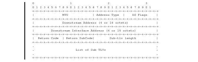
Figure 22 depicts Downstream Detailed Mapping TLV entered in the path-destination belongs to one of the possible outgoing interface of the FEC.
When a 7750 LSR performs a re-merge of one or more ILMs of the P2MP LSP to which the traced S2L sub-LSP belongs, it may block the ILM over which the traced S2L resides. This causes the trace to either fail or to succeed with a missing hop.
A 7750 ingress LER detects a re-merge condition when it receives two or more replies to the same probe, such as the same TTL value. It displays the following message to the user regardless if the trace operation successfully reached the egress LER or was aborted earlier:
“Probe returned multiple responses. Result may be inconsistent.”
The 7750 ingress LER behavior is to always proceed to the next ttl probe when it receives an OK response to a probe or when it times out on a probe. If however it receives replies with an error return code, it must wait until it receives an OK response or it times out. If it times out without receiving an OK reply, the LSP trace must be aborted.
|
•
|
MAC Ping — Provides an end-to-end test to identify the egress customer-facing port where a customer MAC was learned. MAC ping can also be used with a broadcast MAC address to identify all egress points of a service for the specified broadcast MAC.
|
|
•
|
MAC Trace — Provides the ability to trace a specified MAC address hop-by-hop until the last node in the service domain. An SAA test with MAC trace is considered successful when there is a reply from a far-end node indicating that they have the destination MAC address on an egress SAP or the CPM.
|
|
•
|
CPE Ping — Provides the ability to check network connectivity to the specified client device within the VPLS. CPE ping will return the MAC address of the client, as well as the SAP and PE at which it was learned.
|
|
•
|
MAC Populate — Allows specified MAC addresses to be injected in the VPLS service domain. This triggers learning of the injected MAC address by all participating nodes in the service. This tool is generally followed by MAC ping or MAC trace to verify if correct learning occurred.
|
|
•
|
MAC Purge — Allows MAC addresses to be flushed from all nodes in a service domain.
|
The cpe-ping command extends this capability to detecting end-station IP addresses inside a VPLS. A CPE ping for a specific destination IP address within a VPLS will be translated to a MAC-ping towards a broadcast MAC address. Upon receiving such a MAC ping, each peer PE within the VPLS context will trigger an ARP request for the specific IP address. The PE receiving a response to this ARP request will report back to the requesting 7750 SR. It is encouraged to use the source IP address of 0.0.0.0 to prevent the provider’s IP address of being learned by the CE.
Note: This feature does not support IPv6 CPEs
0 1 2 3
0 1 2 3 4 5 6 7 8 9 0 1 2 3 4 5 6 7 8 9 0 1 2 3 4 5 6 7 8 9 0 1
+-+-+-+-+-+-+-+-+-+-+-+-+-+-+-+-+-+-+-+-+-+-+-+-+-+-+-+-+-+-+-+-+
|0 0 0 1| FmtID | Reserved | Channel Type |
+-+-+-+-+-+-+-+-+-+-+-+-+-+-+-+-+-+-+-+-+-+-+-+-+-+-+-+-+-+-+-+-+
0 1 2 3
0 1 2 3 4 5 6 7 8 9 0 1 2 3 4 5 6 7 8 9 0 1 2 3 4 5 6 7 8 9 0 1 0
+-+-+-+-+-+-+-+-+-+-+-+-+-+-+-+-+-+-+-+-+-+-+-+-+-+-+-+-+-+-+-+-+
| 0x0c | 0x04 | CC Types | CV Types |
+-+-+-+-+-+-+-+-+-+-+-+-+-+-+-+-+-+-+-+-+-+-+-+-+-+-+-+-+-+-+-+-+
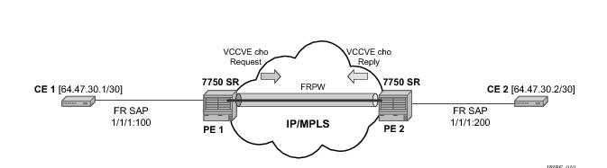
If both PE nodes support more than one of the CC types, then a 7750 SR PE will make use of the one with the lowest type value. For instance, OAM control word will be used in preference to the MPLS router alert label.
The VCCV ping feature is in addition to the service ping OAM feature which can be used to test a service between 7750 SR nodes. The VCCV ping feature can test connectivity of a VLL with any third party node which is compliant to RFC 5085.
Figure 26 displays and example of an application of VCCV ping over a multi-segment pseudowire.
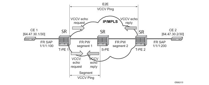
The method is described in draft-hart-pwe3-segmented-pw-vccv, VCCV Extensions for Segmented Pseudo-Wire, and is pending acceptance by the PWE3 working group. In each iteration, the source T-PE or S-PE builds the MPLS echo request message in a way similar to
VCCV Ping. The first message with TTL=1 will have the next-hop S-PE T-LDP session source address in the Remote PE Address field in the pseudowire FEC TLV. Each S-PE which terminates and processes the message will include in the MPLS echo reply message the FEC 128 TLV corresponding the pseudowire segment to its downstream node. The inclusion of the FEC TLV in the echo reply message is allowed in RFC 4379,
Detecting Multi-Protocol Label Switched (MPLS) Data Plane Failures. The source T-PE or S-PE can then build the next echo reply message with TTL=2 to test the next-next hop for the MS-pseudowire. It will copy the FEC TLV it received in the echo reply message into the new echo request message. The process is terminated when the reply is from the egress T-PE or when a timeout occurs. If specified, the max-ttl parameter in the vccv-trace command will stop on SPE before reaching T-PE.
In Figure 26 a trace can be performed on the MS-pseudowire originating from T-PE1 by a single operational command. The following process occurs:
end-to-end – this option allows sending oam atm-ping towards the connection endpoint in the line direction by using OAM end-to-end loopback cells
segment – this option allows sending oam atm-ping towards the segment termination point in the line direction by using OAM segment loopback cells.
|
•
|
Sub-type static must be specified. This indicates to the system that the rest of the command contains parameters that are applied to a static PW with a static PW FEC.
|
vccv-ping static <sdp-id:vc-id> [dest-global-id <global-id> dest-node-id <node-id>] [control-channel ipv4 | non-ip] [fc <fc-name> [profile {in|out}]] [size <octets>] [count <send-count>] [timeout <timeout>] [interval <interval>] [ttl <vc-label-ttl>][src-ip-address <ip-address>]
vccv-trace static <sdp-id:vc-id> [size <octets>][min-ttl <min-vc-label-ttl>][max-ttl <max-vc-label-ttl>][max-fail <no-response-count>][probe-count <probe-count>] [control-channel ipv4 | non-ip] [timeout <timeout-value>][interval <interval-value>][fc <fc-name> [profile {in|out}]][src-ip-address <ip-address>] [detail]
|
•
|
sub-type static must be specified. This indicates to the system that the rest of the command contains parameters specific to a LSP identified by a static LSP FEC.
|
lsp-ping static <lsp-name>
[force]
[path-type [active|working|protect]]
[fc <fc-name> [profile {in|out}]]
[size <octets>]
[ttl <label-ttl>]
[send-count <send-count>]
[timeout <timeout>]
[interval <interval>]
[src-ip-address <ip-address>]
[dest-global-id <dest-global-id> dest-node-id dest-node-id]
[control-channel none | non-ip][detail]
lsp-trace static <lsp-name>
[force]
[path-type [active|working|protect]
[fc <fc-name> [profile {in|out}]]
[max-fail <no-response-count>]
[probe-count <probes-per-hop>]
[size <octets>]
[min-ttl <min-label-ttl>]
[max-ttl <max-label-ttl>]
[timeout <timeout>]
[interval <interval>]
[src-ip-address <ip-address>]
[control-channel none | non-ip]
[downstream-map-tlv <dsmap|ddmap>]
[detail]
The following commands are only valid if the sub-type static option is configured, implying that lsp-name refers to an MPLS-TP tunnel LSP:
path-type. Values: active, working, protect. Default: active.
dest-global-id <global-id>
dest-node-id <node-id>: Default: the
to global-id:node-id from the LSP ID.
control-channel: If this is set to none, then IP encapsulation over an LSP is used with a destination address in the 127/8 range. The source address is set to the system IP address, unless the user specifies a source address using the src-ip-address option. If this is set to non-ip, then non-IP encapsulation over a G-ACh with channel type 0x00025 is used. This is the default for sub-type static. Note that the encapsulation used for the echo reply is the same as the encapsulation used for the echo request.
downstream-map-tlv: LSP Trace commands with this option can only be executed if the control-channel is set to none. The DSMAP/DDMAP TLV is only included in the echo request message if the egress interface is either a numbered IP interface, or an unnumbered IP interface. The TLV will not be included if the egress interface is of type
unnumbered-mpls-tp.
The force parameter causes an LSP ping echo request to be sent on an LSP that has been brought oper-down by BFD (LSP-Ping echo requests would normally be dropped on oper-down LSPs). This parameter is not applicable to SAA.
debug mirror-source 20
sap lag-2:100 ingress egress
exit
mirror-dest 20 create
endpoint "tx" create
exit
spoke-sdp 1000:20 endpoint "tx" create
ingress
vc-label 1000
exit
egress
vc-label 2000
exit
control-word
control-channel-status
exit
pw-path-id
exit
no shutdown
exit
spoke-sdp 2000:20 endpoint "tx" create
ingress
vc-label 1000
exit
egress
vc-label 2000
exit
control-word
control-channel-status
exit
pw-path-id
exit
no shutdown
exit
no shutdown
exit
mirror-dest 20 create
endpoint "rx" create
exit
endpoint "tx" create
exit
remote-source
spoke-sdp 1000:20 endpoint "rx" create ! From node A
ingress
vc-label 2000
exit
egress
vc-label 1000
exit
control-word
control-channel-status
exit
pw-path-id
exit
no shutdown
exit
spoke-sdp 2001:20 endpoint "rx" create ! From node B
ingress
vc-label 2000
exit
egress
vc-label 1000
exit
control-word
control-channel-status
exit
pw-path-id
exit
no shutdown
exit
spoke 3001:20 endpoint "rx" icb create ! ICB from other destination node D
ingress
vc-label 2000
exit
egress
vc-label 1000
exit
control-word
control-channel-status
exit
pw-path-id
exit
no shutdown
exit
sap lag-1:20 endpoint "tx" create
exit
spoke 3000:20 endpoint "tx" icb create ! ICB to other destination node D
ingress
vc-label 1000
exit
egress
vc-label 2000
exit
control-word
control-channel-status
exit
pw-path-id
exit
no shutdown
exit
no shutdown
exit
no shutdown
*A:mlstp-dutA# show router mpls
mpls mpls-labels
*A:mlstp-dutA# show router mpls label
label label-range
*A:mlstp-dutA# show router mpls label-range
===============================================================================
Label Ranges
===============================================================================
Label Type Start Label End Label Aging Total Available
-------------------------------------------------------------------------------
Static-lsp 32 16415 - 16364
Static-svc 16416 32799 - 16376
Dynamic 32800 131071 0 98268
===============================================================================
*A:mlstp-dutA# show router mpls tp-lsp
- tp-lsp [<lsp-name>] [status {up|down}] [from <ip-address>|to <ip-address>]
[detail]
- tp-lsp [<lsp-name>] path [protect|working] [detail]
- tp-lsp [<lsp-name>] protection
<lsp-name> : [32 chars max] - accepts * as wildcard char
<path> : keyword - Display LSP path information.
<protection> : keyword - Display LSP protection information.
<up|down> : keywords - Specify state of the LSP
<ip-address> : a.b.c.d
<detail> : keyword - Display detailed information.
*A:mlstp-dutA# show router mpls tp-lsp
path
protection
to <a.b.c.d>
<lsp-name>
"lsp-32" "lsp-33" "lsp-34" "lsp-35" "lsp-36" "lsp-37" "lsp-38" "lsp-39"
"lsp-40" "lsp-41"
status {up|down}
from <ip-address>
detail
*A:mlstp-dutA# show router mpls tp-lsp "lsp-
"lsp-32" "lsp-33" "lsp-34" "lsp-35" "lsp-36" "lsp-37" "lsp-38" "lsp-39"
"lsp-40" "lsp-41"
*A:mlstp-dutA# show router mpls tp-lsp "lsp-32"
===============================================================================
MPLS MPLS-TP LSPs (Originating)
===============================================================================
LSP Name To Tun Protect Adm Opr
Id Path
-------------------------------------------------------------------------------
lsp-32 0.0.3.234 32 No Up Up
-------------------------------------------------------------------------------
LSPs : 1
===============================================================================
*A:mlstp-dutA# show router mpls tp-lsp "lsp-32" detail
===============================================================================
MPLS MPLS-TP LSPs (Originating) (Detail)
===============================================================================
-------------------------------------------------------------------------------
Type : Originating
-------------------------------------------------------------------------------
LSP Name : lsp-32
LSP Type : MplsTp LSP Tunnel ID : 32
From Node Id: 0.0.3.233+ To Node Id : 0.0.3.234
Adm State : Up Oper State : Up
LSP Up Time : 0d 04:50:47 LSP Down Time : 0d 00:00:00
Transitions : 1 Path Changes : 2
===============================================================================
*A:mlstp-dutA# show router mpls tp-lsp path
===============================================================================
MPLS-TP LSP Path Information
===============================================================================
LSP Name : lsp-32 To : 0.0.3.234
Admin State : Up Oper State : Up
-------------------------------------------------------------------------------
Path NextHop InLabel OutLabel Out I/F Admin Oper
-------------------------------------------------------------------------------
Working 32 32 AtoB_1 Up Down
Protect 2080 2080 AtoC_1 Up Up
===============================================================================
LSP Name : lsp-33 To : 0.0.3.234
Admin State : Up Oper State : Up
-------------------------------------------------------------------------------
Path NextHop InLabel OutLabel Out I/F Admin Oper
-------------------------------------------------------------------------------
Working 33 33 AtoB_1 Up Down
Protect 2082 2082 AtoC_1 Up Up
===============================================================================
LSP Name : lsp-34 To : 0.0.3.234
Admin State : Up Oper State : Up
-------------------------------------------------------------------------------
Path NextHop InLabel OutLabel Out I/F Admin Oper
-------------------------------------------------------------------------------
Working 34 34 AtoB_1 Up Down
Protect 2084 2084 AtoC_1 Up Up
===============================================================================
LSP Name : lsp-35 To : 0.0.3.234
Admin State : Up Oper State : Up
-------------------------------------------------------------------------------
Path NextHop InLabel OutLabel Out I/F Admin Oper
-------------------------------------------------------------------------------
Working 35 35 AtoB_1 Up Down
Protect 2086 2086 AtoC_1 Up Up
===============================================================================
LSP Name : lsp-36 To : 0.0.3.234
Admin State : Up Oper State : Up
-------------------------------------------------------------------------------
Path NextHop InLabel OutLabel Out I/F Admin Oper
-------------------------------------------------------------------------------
Working 36 36 AtoB_1 Up Down
Protect 2088 2088 AtoC_1 Up Up
===============================================================================
LSP Name : lsp-37 To : 0.0.3.234
Admin State : Up Oper State : Up
-------------------------------------------------------------------------------
Path NextHop InLabel OutLabel Out I/F Admin Oper
-------------------------------------------------------------------------------
Working 37 37 AtoB_1 Up Down
Protect 2090 2090 AtoC_1 Up Up
===============================================================================
LSP Name : lsp-38 To : 0.0.3.234
Admin State : Up Oper State : Up
-------------------------------------------------------------------------------
Path NextHop InLabel OutLabel Out I/F Admin Oper
-------------------------------------------------------------------------------
Working 38 38 AtoB_1 Up Down
Protect 2092 2092 AtoC_1 Up Up
===============================================================================
LSP Name : lsp-39 To : 0.0.3.234
Admin State : Up Oper State : Up
-------------------------------------------------------------------------------
Path NextHop InLabel OutLabel Out I/F Admin Oper
-------------------------------------------------------------------------------
Working 39 39 AtoB_1 Up Down
Protect 2094 2094 AtoC_1 Up Up
===============================================================================
LSP Name : lsp-40 To : 0.0.3.234
Admin State : Up Oper State : Up
-------------------------------------------------------------------------------
Path NextHop InLabel OutLabel Out I/F Admin Oper
-------------------------------------------------------------------------------
Working 40 40 AtoB_1 Up Down
Protect 2096 2096 AtoC_1 Up Up
===============================================================================
LSP Name : lsp-41 To : 0.0.3.234
Admin State : Up Oper State : Up
-------------------------------------------------------------------------------
Path NextHop InLabel OutLabel Out I/F Admin Oper
-------------------------------------------------------------------------------
Working 41 41 AtoB_1 Up Down
Protect 2098 2098 AtoC_1 Up Up
*A:mlstp-dutA# show router mpls tp-lsp "lsp-32" path working
===============================================================================
MPLS-TP LSP Working Path Information
LSP: "lsp-32"
===============================================================================
LSP Name : lsp-32 To : 0.0.3.234
Admin State : Up Oper State : Up
-------------------------------------------------------------------------------
Path NextHop InLabel OutLabel Out I/F Admin Oper
-------------------------------------------------------------------------------
Working 32 32 AtoB_1 Up Down
===============================================================================
*A:mlstp-dutA# show router mpls tp-lsp "lsp-32" path protect
===============================================================================
MPLS-TP LSP Protect Path Information
LSP: "lsp-32"
===============================================================================
LSP Name : lsp-32 To : 0.0.3.234
Admin State : Up Oper State : Up
-------------------------------------------------------------------------------
Path NextHop InLabel OutLabel Out I/F Admin Oper
-------------------------------------------------------------------------------
Protect 2080 2080 AtoC_1 Up Up
===============================================================================
*A:mlstp-dutA# show router mpls tp-lsp "lsp-32" path protect detail
===============================================================================
MPLS-TP LSP Protect Path Information
LSP: "lsp-32" (Detail)
===============================================================================
LSP Name : lsp-32 To : 0.0.3.234
Admin State : Up Oper State : Up
Protect path information
-------------------------------------------------------------------------------
Path Type : Protect LSP Num : 2
Path Admin : Up Path Oper : Up
Out Interface : AtoC_1 Next Hop Addr : n/a
In Label : 2080 Out Label : 2080
Path Up Time : 0d 04:52:17 Path Dn Time : 0d 00:00:00
Active Path : Yes Active Time : 0d 00:52:56
MEP information
MEP State : Up BFD : cc
OAM Templ : privatebed-oam-template CC Status : inService
CV Status : unknown
Protect Templ : privatebed-protection-template WTR Count Down: 0 seconds
RX PDU : SF (1,1) TX PDU : SF (1,1)
Defects :
===============================================================================
*A:mlstp-dutA# show router mpls tp-lsp "lsp-32" path working detail
===============================================================================
MPLS-TP LSP Working Path Information
LSP: "lsp-32" (Detail)
===============================================================================
LSP Name : lsp-32 To : 0.0.3.234
Admin State : Up Oper State : Up
Working path information
-------------------------------------------------------------------------------
Path Type : Working LSP Num : 1
Path Admin : Up Path Oper : Down
Down Reason : ccFault ifDn
Out Interface : AtoB_1 Next Hop Addr : n/a
In Label : 32 Out Label : 32
Path Up Time : 0d 00:00:00 Path Dn Time : 0d 00:53:01
Active Path : No Active Time : n/a
MEP information
MEP State : Up BFD : cc
OAM Templ : privatebed-oam-template CC Status : outOfService
CV Status : unknown
===============================================================================
*A:mlstp-dutA#
*A:mlstp-dutA# show router mpls tp-lsp protection
===============================================================================
MPLS-TP LSP Protection Information
Legend: W-Working, P-Protect,
===============================================================================
LSP Name Admin Oper Path Ingr/Egr Act. Rx PDU
State State State Label Path Tx PDU
-------------------------------------------------------------------------------
lsp-32 Up Up W Down 32/32 No SF (1,1)
P Up 2080/2080 Yes SF (1,1)
lsp-33 Up Up W Down 33/33 No SF (1,1)
P Up 2082/2082 Yes SF (1,1)
lsp-34 Up Up W Down 34/34 No SF (1,1)
P Up 2084/2084 Yes SF (1,1)
lsp-35 Up Up W Down 35/35 No SF (1,1)
P Up 2086/2086 Yes SF (1,1)
lsp-36 Up Up W Down 36/36 No SF (1,1)
P Up 2088/2088 Yes SF (1,1)
lsp-37 Up Up W Down 37/37 No SF (1,1)
P Up 2090/2090 Yes SF (1,1)
lsp-38 Up Up W Down 38/38 No SF (1,1)
P Up 2092/2092 Yes SF (1,1)
lsp-39 Up Up W Down 39/39 No SF (1,1)
P Up 2094/2094 Yes SF (1,1)
lsp-40 Up Up W Down 40/40 No SF (1,1)
P Up 2096/2096 Yes SF (1,1)
lsp-41 Up Up W Down 41/41 No SF (1,1)
P Up 2098/2098 Yes SF (1,1)
-------------------------------------------------------------------------------
No. of MPLS-TP LSPs: 10
===============================================================================
*A:mlstp-dutA# show router bfd
- bfd
bfd-template - Display BFD Template information
interface - Display Interfaces with BFD
session - Display session information
*A:mlstp-dutA# show router bfd bfd-template "privatebed-bfd-template"
===============================================================================
BFD Template privatebed-bfd-template
===============================================================================
Template Name : privatebed-* Template Type : cpmNp
Transmit Timer : 10 msec Receive Timer : 10 msec
CV Transmit Interval : 1000 msec
Template Multiplier : 3 Echo Receive Interval : 100 msec
Mpls-tp Association
privatebed-oam-template
===============================================================================
* indicates that the corresponding row element may have been truncated.
*A:mlstp-dutA# show router bfd session
===============================================================================
BFD Session
===============================================================================
Interface/Lsp Name State Tx Intvl Rx Intvl Multipl
Remote Address/Info Protocols Tx Pkts Rx Pkts Type
-------------------------------------------------------------------------------
wp::lsp-32 Down (1) 1000 1000 3
0::0.0.0.0 mplsTp N/A N/A cpm-np
wp::lsp-33 Down (1) 1000 1000 3
0::0.0.0.0 mplsTp N/A N/A cpm-np
wp::lsp-34 Down (1) 1000 1000 3
0::0.0.0.0 mplsTp N/A N/A cpm-np
wp::lsp-35 Down (1) 1000 1000 3
0::0.0.0.0 mplsTp N/A N/A cpm-np
wp::lsp-36 Down (1) 1000 1000 3
0::0.0.0.0 mplsTp N/A N/A cpm-np
wp::lsp-37 Down (1) 1000 1000 3
0::0.0.0.0 mplsTp N/A N/A cpm-np
wp::lsp-38 Down (1) 1000 1000 3
0::0.0.0.0 mplsTp N/A N/A cpm-np
wp::lsp-39 Down (1) 1000 1000 3
0::0.0.0.0 mplsTp N/A N/A cpm-np
wp::lsp-40 Down (1) 1000 1000 3
0::0.0.0.0 mplsTp N/A N/A cpm-np
wp::lsp-41 Down (1) 1000 1000 3
0::0.0.0.0 mplsTp N/A N/A cpm-np
pp::lsp-32 Up (3) 1000 1000 3
0::0.0.0.0 mplsTp N/A N/A cpm-np
pp::lsp-33 Up (3) 1000 1000 3
0::0.0.0.0 mplsTp N/A N/A cpm-np
pp::lsp-34 Up (3) 1000 1000 3
0::0.0.0.0 mplsTp N/A N/A cpm-np
pp::lsp-35 Up (3) 1000 1000 3
0::0.0.0.0 mplsTp N/A N/A cpm-np
pp::lsp-36 Up (3) 1000 1000 3
0::0.0.0.0 mplsTp N/A N/A cpm-np
pp::lsp-37 Up (3) 1000 1000 3
0::0.0.0.0 mplsTp N/A N/A cpm-np
pp::lsp-38 Up (3) 1000 1000 3
0::0.0.0.0 mplsTp N/A N/A cpm-np
pp::lsp-39 Up (3) 1000 1000 3
0::0.0.0.0 mplsTp N/A N/A cpm-np
pp::lsp-40 Up (3) 1000 1000 3
0::0.0.0.0 mplsTp N/A N/A cpm-np
pp::lsp-41 Up (3) 1000 1000 3
0::0.0.0.0 mplsTp N/A N/A cpm-np
-------------------------------------------------------------------------------
No. of BFD sessions: 20
-------------------------------------------------------------------------------
wp = Working path pp = Protecting path
===============================================================================
*A:mlstp-dutA# show router mpls mpls-tp
- mpls-tp
oam-template - Display MPLS-TP OAM Template information
protection-tem* - Display MPLS-TP Protection Template information
status - Display MPLS-TP system configuration
transit-path - Display MPLS-TP Tunnel information
*A:mlstp-dutA# show router mpls mpls-tp oam-template
===============================================================================
MPLS-TP OAM Templates
===============================================================================
Template Name : privatebed-oam-template Router ID : 1
BFD Template : privatebed-bfd-template Hold-Down Time: 0 centiseconds
Hold-Up Time : 20 deciseconds
===============================================================================
*A:mlstp-dutA# show router mpls mpls-tp protection-template
===============================================================================
MPLS-TP Protection Templates
===============================================================================
Template Name : privatebed-protection-template Router ID : 1
Protection Mode: one2one Direction : bidirectional
Revertive : revertive Wait-to-Restore: 300sec
Rapid-PSC-Timer: 10ms Slow-PSC-Timer : 5sec
===============================================================================
*A:mlstp-dutA# show router mpls mpls-tp status
===============================================================================
MPLS-TP Status
===============================================================================
Admin Status : Up
Global ID : 42 Node ID : 0.0.3.233
Tunnel Id Min : 1 Tunnel Id Max : 4096
===============================================================================
*A:mlstp-dutA# show router mpls mpls-tp transit-path
- transit-path [<path-name>] [detail]
<path-name> : [32 chars max]
<detail> : keyword - Display detailed information.
A:mplstp-dutC# show router mpls mpls-tp transit-path
- transit-path [<path-name>] [detail]
<path-name> : [32 chars max]
<detail> : keyword - Display detailed information.
A:mplstp-dutC# show router mpls mpls-tp transit-path
<path-name>
"tp-32" "tp-33" "tp-34" "tp-35" "tp-36" "tp-37" "tp-38" "tp-39"
"tp-40" "tp-41"
detail
A:mplstp-dutC# show router mpls mpls-tp transit-path "tp-32"
===============================================================================
MPLS-TP Transit tp-32 Path Information
===============================================================================
Path Name : tp-32
Admin State : Up Oper State : Up
------------------------------------------------------------------
Path NextHop InLabel OutLabel Out I/F
------------------------------------------------------------------
FP 2080 2081 CtoB_1
RP 2081 2080 CtoA_1
===============================================================================
A:mplstp-dutC# show router mpls mpls-tp transit-path "tp-32" detail
===============================================================================
MPLS-TP Transit tp-32 Path Information (Detail)
===============================================================================
Path Name : tp-32
Admin State : Up Oper State : Up
-------------------------------------------------------------------------------
Path ID configuration
Src Global ID : 42 Dst Global ID : 42
Src Node ID : 0.0.3.234 Dst Node ID : 0.0.3.233
LSP Number : 2 Dst Tunnel Num: 32
Forward Path configuration
In Label : 2080 Out Label : 2081
Out Interface : CtoB_1 Next Hop Addr : n/a
Reverse Path configuration
In Label : 2081 Out Label : 2080
Out Interface : CtoA_1 Next Hop Addr : n/a
===============================================================================
A:mplstp-dutC#
*A:mlstp-dutA# show router interface "AtoB_1"
===============================================================================
Interface Table (Router: Base)
===============================================================================
Interface-Name Adm Opr(v4/v6) Mode Port/SapId
IP-Address PfxState
-------------------------------------------------------------------------------
AtoB_1 Down Down/-- Network 1/2/3:1
Unnumbered If[system] n/a
-------------------------------------------------------------------------------
Interfaces : 1
*A:mlstp-dutA# show service id 1 all
===============================================================================
Service Detailed Information
===============================================================================
Service Id : 1 Vpn Id : 0
Service Type : Epipe
Name : (Not Specified)
Description : (Not Specified)
Customer Id : 1 Creation Origin : manual
Last Status Change: 12/03/2012 15:26:20
Last Mgmt Change : 12/03/2012 15:24:57
Admin State : Up Oper State : Up
MTU : 1514
Vc Switching : False
SAP Count : 1 SDP Bind Count : 1
Per Svc Hashing : Disabled
Force QTag Fwd : Disabled
-------------------------------------------------------------------------------
ETH-CFM service specifics
-------------------------------------------------------------------------------
Tunnel Faults : ignore
-------------------------------------------------------------------------------
Service Destination Points(SDPs)
-------------------------------------------------------------------------------
-------------------------------------------------------------------------------
Sdp Id 32:1 -(0.0.3.234:42)
-------------------------------------------------------------------------------
Description : (Not Specified)
SDP Id : 32:1 Type : Spoke
Spoke Descr : (Not Specified)
VC Type : Ether VC Tag : n/a
Admin Path MTU : 0 Oper Path MTU : 9186
Delivery : MPLS
Far End : 0.0.3.234:42
Tunnel Far End : n/a LSP Types : MPLSTP
Hash Label : Disabled Hash Lbl Sig Cap : Disabled
Oper Hash Label : Disabled
Admin State : Up Oper State : Up
Acct. Pol : None Collect Stats : Disabled
Ingress Label : 16416 Egress Label : 16416
Ingr Mac Fltr-Id : n/a Egr Mac Fltr-Id : n/a
Ingr IP Fltr-Id : n/a Egr IP Fltr-Id : n/a
Ingr IPv6 Fltr-Id : n/a Egr IPv6 Fltr-Id : n/a
Admin ControlWord : Preferred Oper ControlWord : True
Admin BW(Kbps) : 0 Oper BW(Kbps) : 0
Last Status Change : 12/03/2012 15:26:20 Signaling : None
Last Mgmt Change : 12/03/2012 15:24:57 Force Vlan-Vc : Disabled
Endpoint : N/A Precedence : 4
PW Status Sig : Enabled
Class Fwding State : Down
Flags : None
Local Pw Bits : None
Peer Pw Bits : None
Peer Fault Ip : None
Peer Vccv CV Bits : None
Peer Vccv CC Bits : None
Application Profile: None
Standby Sig Slave : False
Block On Peer Fault: False
Ingress Qos Policy : (none) Egress Qos Policy : (none)
Ingress FP QGrp : (none) Egress Port QGrp : (none)
Ing FP QGrp Inst : (none) Egr Port QGrp Inst: (none)
Statistics :
I. Fwd. Pkts. : 272969957 I. Dro. Pkts. : 0
E. Fwd. Pkts. : 273017433 E. Fwd. Octets : 16381033352
-------------------------------------------------------------------------------
Control Channel Status
-------------------------------------------------------------------------------
PW Status : enabled Refresh Timer : 66 secs
Peer Status Expire : false Clear On Timeout : true
-------------------------------------------------------------------------------
SDP-BIND PW Path Information
-------------------------------------------------------------------------------
AGI : 1:1
SAII Type2 : 42:0.0.3.234:1
TAII Type2 : 42:0.0.3.233:1
-------------------------------------------------------------------------------
RSVP/Static LSPs
-------------------------------------------------------------------------------
Associated LSP List :
Lsp Name : lsp-32
Admin State : Up Oper State : Up
*A:mlstp-dutA# show service id [1..4] all | match "Control Channel" pre-lines 1 post-lines 5
-------------------------------------------------------------------------------
Control Channel Status
-------------------------------------------------------------------------------
PW Status : enabled Refresh Timer : 66 secs
Peer Status Expire : false Clear On Timeout : true
-------------------------------------------------------------------------------
-------------------------------------------------------------------------------
Control Channel Status
-------------------------------------------------------------------------------
PW Status : enabled Refresh Timer : 66 secs
Peer Status Expire : false Clear On Timeout : true
-------------------------------------------------------------------------------
*A:mlstp-dutA# show service id [1..4] all | match SDP-BIND pre-lines 1 post-lines 5
-------------------------------------------------------------------------------
SDP-BIND PW Path Information
-------------------------------------------------------------------------------
AGI : 1:1
SAII Type2 : 42:0.0.3.234:1
TAII Type2 : 42:0.0.3.233:1
-------------------------------------------------------------------------------
SDP-BIND PW Path Information
-------------------------------------------------------------------------------
AGI : 1:2
SAII Type2 : 42:0.0.3.234:2
TAII Type2 : 42:0.0.3.233:2
-------------------------------------------------------------------------------
SDP-BIND PW Path Information
-------------------------------------------------------------------------------
AGI : 1:3
SAII Type2 : 42:0.0.3.234:3
TAII Type2 : 42:0.0.3.233:3
-------------------------------------------------------------------------------
SDP-BIND PW Path Information
-------------------------------------------------------------------------------
AGI : 1:4
SAII Type2 : 42:0.0.3.234:4
TAII Type2 : 42:0.0.3.233:4
A:mlstp-dutA# tools dump router mpls tp-tunnel
- tp-tunnel <lsp-name> [clear]
- tp-tunnel id <tunnel-id> [clear]
<lsp-name> : [32 chars max]
<tunnel-id> : [1..61440]
<clear> : keyword - clear stats after reading
*A:mlstp-dutA# tools dump router mpls tp-tunnel "lsp-
"lsp-32" "lsp-33" "lsp-34" "lsp-35" "lsp-36" "lsp-37" "lsp-38" "lsp-39"
"lsp-40" "lsp-41"
*A:mlstp-dutA# tools dump router mpls tp-tunnel "lsp-32"
Idx: 1-32 (Up/Up): pgId 4, paths 2, operChg 1, Active: Protect
TunnelId: 42::0.0.3.233::32-42::0.0.3.234::32
PgState: Dn, Cnt/Tm: Dn 1/000 04:00:48.160 Up:3/000 00:01:25.840
MplsMsg: tpDn 0/000 00:00:00.000, tunDn 0/000 00:00:00.000
wpDn 0/000 00:00:00.000, ppDn 0/000 00:00:00.000
wpDel 0/000 00:00:00.000, ppDel 0/000 00:00:00.000
tunUp 1/000 00:00:02.070
Paths:
Work (Up/Dn): Lsp 1, Lbl 32/32, If 2/128 (1/2/3 : 0.0.0.0)
Tmpl: ptc: , oam: privatebed-oam-template (bfd: privatebed-bfd-template(np)-10 ms)
Bfd: Mode CC state Dn/Up handle 160005/0
Bfd-CC (Cnt/Tm): Dn 1/000 04:00:48.160 Up:1/000 00:01:23.970
State: Admin Up (1::1::1) port Up , if Dn , operChg 2
DnReasons: ccFault ifDn
Protect (Up/Up): Lsp 2, Lbl 2080/2080, If 3/127 (5/1/1 : 0.0.0.0)
Tmpl: ptc: privatebed-protection-template, oam: privatebed-oam-template (bfd: privatebed-bfd-template(np)-10 ms)
Bfd: Mode CC state Up/Up handle 160006/0
Bfd-CC (Cnt/Tm): Dn 0/000 00:00:00.000 Up:1/000 00:01:25.410
State: Admin Up (1::1::1) port Up , if Up , operChg 1
Aps: Rx - 5, raw 3616, nok 0(), txRaw - 3636, revert Y
Pdu: Rx - 0x1a-21::0101 (SF), Tx - 0x1a-21::0101 (SF)
State: PF:W:L LastEvt pdu (L-SFw/R-SFw)
Tmrs: slow
Defects: None Now: 000 05:02:19.130
Seq Event state TxPdu RxPdu Dir Act Time
=== ====== ======== ========== ========== ===== ==== ================
000 start UA:P:L SF (0,0) NR (0,0) Tx--> Work 000 00:00:02.080
001 pdu UA:P:L SF (0,0) SF (0,0) Rx<-- Work 000 00:01:24.860
002 pdu UA:P:L SF (0,0) NR (0,0) Rx<-- Work 000 00:01:26.860
003 pUp NR NR (0,0) NR (0,0) Tx--> Work 000 00:01:27.440
004 pdu NR NR (0,0) NR (0,0) Rx<-- Work 000 00:01:28.760
005 wDn PF:W:L SF (1,1) NR (0,0) Tx--> Prot 000 04:00:48.160
006 pdu PF:W:L SF (1,1) NR (0,1) Rx<-- Prot 000 04:00:48.160
007 pdu PF:W:L SF (1,1) SF (1,1) Rx<-- Prot 000 04:00:51.080
*A:bksim1611# /debug service id 700 sdp 200:700 event-type
{config-change|oper-status-change|neighbor-discovery|control-channel-status}
*A:bksim1611# /debug service id 700 sdp 200:700 event-type control-channel-status
*A:bksim1611#
1 2012/08/31 09:56:12.09 EST MINOR: DEBUG #2001 Base PW STATUS SIG PKT (RX):
"PW STATUS SIG PKT (RX)::
Sdp Bind 200:700 Instance 3
Version : 0x0
PW OAM Msg Type : 0x27
Refresh Time : 0xa
Total TLV Length : 0x8
Flags : 0x0
TLV Type : 0x96a
TLV Len : 0x4
PW Status Bits : 0x0
"
2 2012/08/31 09:56:22.09 EST MINOR: DEBUG #2001 Base PW STATUS SIG PKT (RX):
"PW STATUS SIG PKT (RX)::
Sdp Bind 200:700 Instance 3
Version : 0x0
PW OAM Msg Type : 0x27
Refresh Time : 0xa
Total TLV Length : 0x8
Flags : 0x0
TLV Type : 0x96a
TLV Len : 0x4
PW Status Bits : 0x0
"
3 2012/08/31 09:56:29.44 EST MINOR: DEBUG #2001 Base PW STATUS SIG PKT (TX):
"PW STATUS SIG PKT (TX)::
Sdp Bind 200:700 Instance 3
Version : 0x0
PW OAM Msg Type : 0x27
Refresh Time : 0x1e
Total TLV Length : 0x8
Flags : 0x0
TLV Type : 0x96a
TLV Len : 0x4
PW Status Bits : 0x0
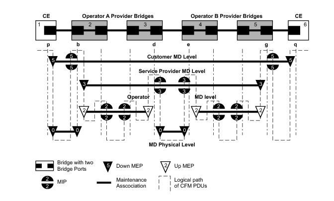
Maintenance Association (MA)/Maintenance Entity Group (MEG) is the construct where the different management entities will be contained. Each MA is uniquely identified by its MA-ID. The MA-ID is comprised of the by the MD level and MA name and associated format. This is another administrative context where the linkage is made between the domain and the service using the bridging-identifier configuration option. The IEEE and the ITU-T use their own specific formats. The MA short name formats (0-255) have been divided between the IEEE (0-31, 64-255) and the ITU-T (32-63), with five currently defined (1-4, 32). Even though the different standards bodies do not have specific support for the others formats a Y.1731 context can be configured using the IEEE format options.
configure eth-cfm domain 3 format none level 3
configure eth-cfm domain 4 format string name IEEE-Domain level 4
show eth-cfm domain
===============================================================================
CFM Domain Table
===============================================================================
Md-index Level Name Format
-------------------------------------------------------------------------------
3 3 none
4 4 IEEE-Domain charString
===============================================================================
The chassis does not support a domain format of none for the 802.1ag contexts. The domain index, the first numerical value, is not related to the level, even though in this example they do match.
config>eth-cfm# info
----------------------------------------------
domain 3 format none level 3
association 1 format icc-based name "123456789abcd"
bridge-identifier 100
exit
exit
association 2 format string name "Y1731ContextIEEEFormat"
bridge-identifier 300
exit
exit
exit
domain 4 name "IEEE-Domain" level 4
association 1 format string name "UpTo45CharactersForIEEEString"
bridge-identifier 100
exit
ccm-interval 1
exit
exit
----------------------------------------------
*A:cses-E01>config>eth-cfm# show eth-cfm association
===============================================================================
CFM Association Table
===============================================================================
Md-index Ma-index Name CCM-intrvl Hold-time Bridge-id
-------------------------------------------------------------------------------
3 1 123456789abcd 10 n/a 100
3 2 Y1731ContextIEEEFormat 10 n/a 300
4 1 UpTo45CharactersForIEEE* 1 n/a 100
===============================================================================
Maintenance Endpoint (MEP)/MEG Endpoint (MEP) are the workhorses of ETH-CFM. A MEP is the unique identification within the association (0-8191). Each MEP is uniquely identified by the MA-ID, MEPID tuple. This management entity is responsible for initiating, processing and terminating ETH-CFM functions, following the nesting rules. MEPs form the boundaries which prevent the ETH-CFM packets from flowing beyond the specific scope of responsibility. A MEP has direction, up or
down. Each indicates the directions packets will be generated; UP toward the switch fabric,
down toward the SAP away from the fabric. Each MEP has an active and passive side. Packets that enter the active point of the MEP will be compared to the existing level and processed accordingly. Packets that enter the passive side of the MEP are passed transparently through the MEP. Each MEP contained within the same maintenance association and with the same level (MA-ID) represents points within a single service. MEP creation on a SAP is allowed only for Ethernet ports with NULL, q-tags, q-in-q encapsulations. MEPs may also be created on SDP bindings.
There are two locations in the configuration where ETH-CFM is defined. The domains, associations (including linkage to the service id), MIP creation method, common ETH-CFM functions and remote MEPs are defined under the top level eth-cfm command. It is important to note, when Y.1731 functions are required the context under which the MEPs are configured must follow the Y.1731 specific formats (domain format of none). Once these parameters have been entered, the MEP and possibly the MIP can be defined within the service under the SAP or SDP binding.
Note1: Ethernet-Tunnels and Ethernet-Rings are not configurable under all service types. Any service restrictions for MEP direction or MIP support will override the generic capability of the Ethernet-Tunnel or Ethernet-Ring MPs. Please check the applicable user guide for applicability
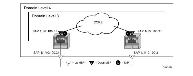
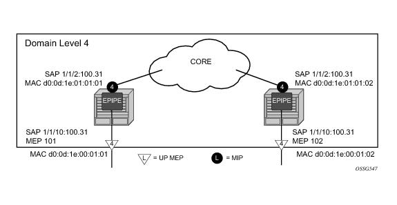
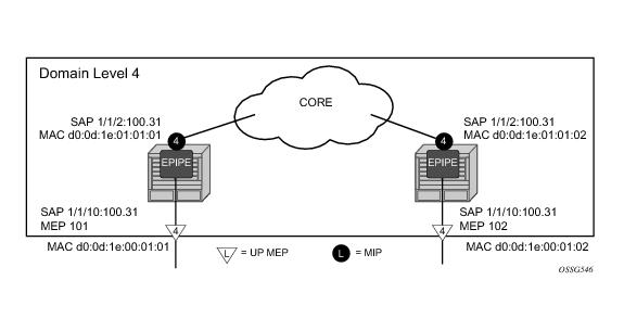
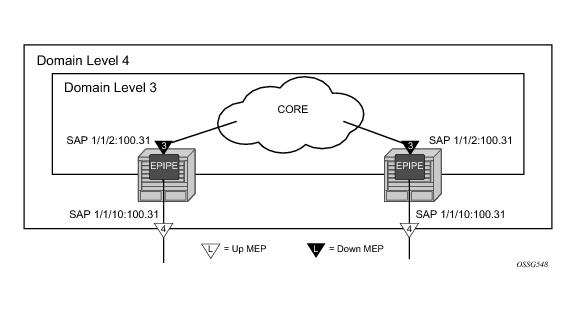
Figure 29 illustrates the usage of an EPIPE on two different nodes that are connected using ether SAP 1/1/2:100.31. The SAP 1/1/10:100.31 is an access port that is not used to connect the two nodes.
NODE1
config>eth-cfm# info
----------------------------------------------
domain 3 format none level 3
association 1 format icc-based name "03-0000000101"
bridge-identifier 100
exit
exit
exit
domain 4 format none level 4
association 1 format icc-based name "04-0000000102"
bridge-identifier 100
exit
exit
exit
*A:cses-E01>config>service>epipe# info
----------------------------------------------
sap 1/1/2:100.31 create
eth-cfm
mep 111 domain 3 association 1 direction down
mac-address d0:0d:1e:00:01:11
no shutdown
exit
exit
exit
sap 1/1/10:100.31 create
eth-cfm
mep 101 domain 4 association 1 direction up
mac-address d0:0d:1e:00:01:01
no shutdown
exit
exit
exit
no shutdown
----------------------------------------------
NODE 2
eth-cfm# info
----------------------------------------------
domain 3 format none level 3
association 1 format icc-based name "03-0000000101"
bridge-identifier 100
exit
exit
exit
domain 4 format none level 4
association 1 format icc-based name "04-0000000102"
bridge-identifier 100
exit
exit
exit
----------------------------------------------
*A:cses-E02>config>service>epipe# info
----------------------------------------------
sap 1/1/2:100.31 create
eth-cfm
mep 112 domain 3 association 1 direction down
mac-address d0:0d:1e:00:01:12
no shutdown
exit
exit
exit
sap 1/1/10:100.31 create
eth-cfm
mep 102 domain 4 association 1 direction up
mac-address d0:0d:1e:00:01:02
no shutdown
exit
exit
exit
no shutdown
----------------------------------------------
*A:cses-E02>config>service>epipe#
show eth-cfm cfm-stack-table
===============================================================================
CFM Stack Table Defect Legend:
R = Rdi, M = MacStatus, C = RemoteCCM, E = ErrorCCM, X = XconCCM, A = AisRx
===============================================================================
CFM SAP Stack Table
===============================================================================
Sap Lvl Dir Md-index Ma-index MepId Mac-address Defect
-------------------------------------------------------------------------------
1/1/2:100.31 3 Down 3 1 111 90:f3:01:01:00:02 ------
1/1/10:100.31 4 Up 4 1 101 d0:0d:1e:00:01:01 ------
===============================================================================
Figure 30 illustrates the creation of and explicit MIP.
NODE1
config>eth-cfm# info
----------------------------------------------
domain 3 format none level 3
association 1 format icc-based name "03-0000000101"
bridge-identifier 100
exit
exit
exit
domain 4 format none level 4
association 1 format icc-based name "04-0000000102"
bridge-identifier 100
exit
exit
association 2 format icc-based name "04-MIP0000102"
bridge-identifier 100
mhf-creation explicit
exit
exit
exit
config>service>epipe# info
----------------------------------------------
sap 1/1/2:100.31 create
eth-cfm
mep 111 domain 3 association 1 direction down
mac-address d0:0d:1e:00:01:11
no shutdown
exit
exit
exit
sap 1/1/10:100.31 create
eth-cfm
mep 101 domain 4 association 1 direction up
mac-address d0:0d:1e:00:01:01
no shutdown
exit
exit
exit
no shutdown
----------------------------------------------
NODE 2
eth-cfm# info
----------------------------------------------
domain 3 format none level 3
association 1 format icc-based name "03-0000000101"
bridge-identifier 100
exit
exit
exit
domain 4 format none level 4
association 1 format icc-based name "04-0000000102"
bridge-identifier 100
exit
exit
association 2 format icc-based name "04-MIP0000102"
bridge-identifier 100
mhf-creation explicit
exit
exit
exit
----------------------------------------------
config>service>epipe# info
----------------------------------------------
sap 1/1/2:100.31 create
eth-cfm
mep 112 domain 3 association 1 direction down
mac-address d0:0d:1e:00:01:12
no shutdown
exit
exit
exit
sap 1/1/10:100.31 create
eth-cfm
mep 102 domain 4 association 1 direction up
mac-address d0:0d:1e:00:01:02
no shutdown
exit
exit
exit
no shutdown
----------------------------------------------
An addition of association 2 under domain four includes the mhf-creation explicit statement has been included. This means that when the level 3 MEP is assigned to the SAP 1/1/2:100.31 using the definition in domain 3 association 1, creating the higher level MIP on the same SAP. Since a MIP does not have directionality “Both” sides are active. The service configuration and MEP configuration within the service did not change.
show eth-cfm cfm-stack-table
===============================================================================
CFM Stack Table Defect Legend:
R = Rdi, M = MacStatus, C = RemoteCCM, E = ErrorCCM, X = XconCCM, A = AisRx
===============================================================================
CFM SAP Stack Table
===============================================================================
Sap Lvl Dir Md-index Ma-index MepId Mac-address Defect
-------------------------------------------------------------------------------
1/1/2:100.31 3 Down 3 1 111 d0:0d:1e:00:01:11 ------
1/1/2:100.31 4 Both 4 2 MIP 90:f3:01:01:00:02 ------
1/1/10:100.31 4 Up 4 1 101 d0:0d:1e:00:01:01 ------
===============================================================================
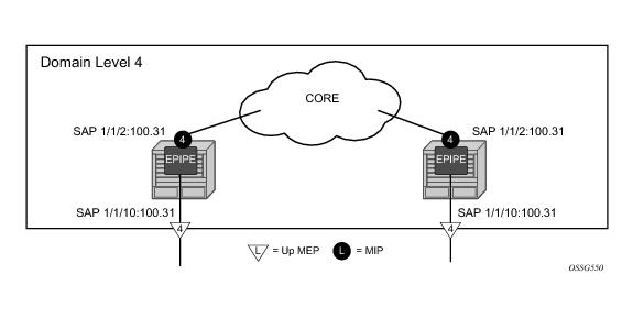
Figure 31 illustrates a simpler method that does not require the creation of the lower level MEP. The operator simply defines the association parameters and uses the
mhf-creation default setting, then places the MIP on the SAP of their choice.
NODE1
config>eth-cfm# info
----------------------------------------------
domain 4 format none level 4
association 1 format icc-based name "04-0000000102"
bridge-identifier 100
exit
exit
association 2 format icc-based name "04-MIP0000102"
bridge-identifier 100
mhf-creation default
exit
exit
exit
----------------------------------------------
config>service>epipe# info
----------------------------------------------
sap 1/1/2:100.31 create
eth-cfm
mip mac d0:0d:1e:01:01:01
exit
exit
sap 1/1/10:100.31 create
eth-cfm
mep 101 domain 4 association 1 direction up
mac-address d0:0d:1e:00:01:01
no shutdown
exit
exit
exit
no shutdown
----------------------------------------------
# show eth-cfm cfm-stack-table
===============================================================================
CFM Stack Table Defect Legend:
R = Rdi, M = MacStatus, C = RemoteCCM, E = ErrorCCM, X = XconCCM, A = AisRx
===============================================================================
CFM SAP Stack Table
===============================================================================
Sap Lvl Dir Md-index Ma-index MepId Mac-address Defect
-------------------------------------------------------------------------------
1/1/2:100.31 4 Both 4 2 MIP d0:0d:1e:01:01:01 ------
1/1/10:100.31 4 Up 4 1 101 d0:0d:1e:00:01:01 ------
===============================================================================
NODE2
config>eth-cfm# info
----------------------------------------------
domain 4 format none level 4
association 1 format icc-based name "04-0000000102"
bridge-identifier 100
exit
exit
association 2 format icc-based name "04-MIP0000102"
bridge-identifier 100
mhf-creation default
exit
exit
exit
----------------------------------------------
config>service>epipe# info
----------------------------------------------
sap 1/1/2:100.31 create
eth-cfm
mip mac d0:0d:1e:01:01:02
exit
exit
sap 1/1/10:100.31 create
eth-cfm
mep 102 domain 4 association 1 direction up
mac-address d0:0d:1e:00:01:02
no shutdown
exit
exit
exit
no shutdown
----------------------------------------------
# show eth-cfm cfm-stack-table
===============================================================================
CFM Stack Table Defect Legend:
R = Rdi, M = MacStatus, C = RemoteCCM, E = ErrorCCM, X = XconCCM, A = AisRx
===============================================================================
CFM SAP Stack Table
===============================================================================
Sap Lvl Dir Md-index Ma-index MepId Mac-address Defect
-------------------------------------------------------------------------------
1/1/2:100.31 4 Both 4 2 MIP d0:0d:1e:01:01:02 ------
1/1/10:100.31 4 Up 4 1 102 d0:0d:1e:00:01:02 ------
===============================================================================
Figure 32 shows the detailed IEEE representation of MEPs, MIPs, levels and associations, using the standards defined icons.
Table 4 shows how packets that would normally bypass the ETH-CFM extraction would be extracted when Primary VLAN is configured. This assumes that the processing rules for MEPs and MIPs is met, E-type 0x8902, Levels and OpCodes.
INFO: ETH_CFM #1341 Unsupported MA ccm-interval for this MEP - MEP 1/112/21 conflicts with sub-second config on this MA
MINOR: ETH_CFM #1341 Unsupported MA ccm-interval for this MEP - MEP 1/112/21 conflicts with sub-second config on this MA
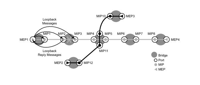
A loopback message is generated by an MEP to its peer MEP or a MIP (Figure 33). The functions are similar to an IP ping to verify Ethernet connectivity between the nodes.
# oam eth-cfm loopback d0:0d:1e:01:01:02 mep 101 domain 4 association
Eth-Cfm Loopback Test Initiated: Mac-Address: d0:0d:1e:01:01:02, out sap: 1/1/10:100.31
Sent 5 packets, received 5 packets [0 out-of-order, 0 Bad Msdu]
# oam eth-cfm loopback d0:0d:1e:00:01:02 mep 101 domain 4 association
Eth-Cfm Loopback Test Initiated: Mac-Address: d0:0d:1e:00:01:02, out sap: 1/1/10:100.31
Sent 5 packets, received 5 packets [0 out-of-order, 0 Bad Msdu]
This on demand operation tool is used to quickly check the reachability of all MEPs within an Association. A multicast address can be coded as the destination of an oam eth-cm loopback command. The specific class 1 multicast MAC address or the keyword “multicast” can be used as the destination for the loopback command. The class 1 ETH-CFM multicast address is in the format 01:80:C2:00:00:3x (where x = 0 - 7 and is the number of the domain level for the source MEP). When the “multicast” option is used, the class 1 multicast destination is built according to the local MEP level initiating the test.
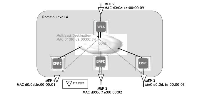
Figure 35 displays a a four node hub and spoke network. The service has a level 4 UP MEP configured on one of the SAPs wherever the service exists. In the example below, a multicast loopback is issued from the MEP 9, the level 4 MEP on the VPLS hub. Each of the remote UP MEPs will process the multicast loopback request, responding with the appropriate unicast LBR.
The following output is shown from the VPLS hub containing MEP 9. The example displays a well behaved and fully connected service instance where all packets are responded to and in the proper order. The SeqNum in the
Mep Multicast Loopback Information section is the sequence number that is set by the instantiating node as it generates the LBM. The
Rx Index is the order in which the packets were received from the responding MEP.
oam eth-cfm loopback multicast mep 9 domain 14 association 1 send-count 5
Eth-Cfm Loopback Test Initiated: Mac-Address: multicast, out service: 1
MAC Address Receive Order
-------------------------------------------------------------------------------
d0:0d:1e:00:00:01 1 2 3 4 5
d0:0d:1e:00:00:02 1 2 3 4 5
d0:0d:1e:00:00:03 1 2 3 4 5
Sent 5 multicast packets, received 15 packets
show eth-cfm mep 9 domain 14 association 1 loopback ===============================================================================
Eth-Cfm MEP Configuration Information
===============================================================================
Md-index : 14 Direction : Up
Ma-index : 1 Admin : Enabled
MepId : 9 CCM-Enable : Disabled
SvcId : 1
Description : (Not Specified)
FngState : fngReset ControlMep : False
LowestDefectPri : macRemErrXcon HighestDefect : none
Defect Flags : None
Mac Address : d0:0d:1e:00:00:09 ControlMep : False
CcmLtmPriority : 7
CcmTx : 0 CcmSequenceErr : 0
Fault Propagation : disabled FacilityFault : n/a
MA-CcmInterval : 10 MA-CcmHoldTime : 0ms
Eth-1Dm Threshold : 3(sec) MD-Level : 3
Eth-Ais: : Disabled
Eth-Tst: : Disabled
Redundancy:
MC-LAG State : n/a
CcmLastFailure Frame:
None
XconCcmFailure Frame:
None
-------------------------------------------------------------------------------
Mep Loopback Information
-------------------------------------------------------------------------------
LbRxReply : 0 LbRxBadOrder : 0
LbRxBadMsdu : 0 LbTxReply : 0
LbNextSequence : 7 LtNextSequence : 1
LbStatus : False LbResultOk : True
DestIsMepId : False DestMepId : 0
DestMac : 00:00:00:00:00:00 SendCount : 0
VlanDropEnable : True VlanPriority : 7
Data TLV:
None
-------------------------------------------------------------------------------
Mep Multicast Loopback Information
-------------------------------------------------------------------------------
MAC Address: d0:0d:1e:00:00:01 SeqNum: 2 Rx Index: 1
MAC Address: d0:0d:1e:00:00:01 SeqNum: 3 Rx Index: 2
MAC Address: d0:0d:1e:00:00:01 SeqNum: 4 Rx Index: 3
MAC Address: d0:0d:1e:00:00:01 SeqNum: 5 Rx Index: 4
MAC Address: d0:0d:1e:00:00:01 SeqNum: 6 Rx Index: 5
MAC Address: d0:0d:1e:00:00:02 SeqNum: 2 Rx Index: 1
MAC Address: d0:0d:1e:00:00:02 SeqNum: 3 Rx Index: 2
MAC Address: d0:0d:1e:00:00:02 SeqNum: 4 Rx Index: 3
MAC Address: d0:0d:1e:00:00:02 SeqNum: 5 Rx Index: 4
MAC Address: d0:0d:1e:00:00:02 SeqNum: 6 Rx Index: 5
MAC Address: d0:0d:1e:00:00:03 SeqNum: 2 Rx Index: 1
MAC Address: d0:0d:1e:00:00:03 SeqNum: 3 Rx Index: 2
MAC Address: d0:0d:1e:00:00:03 SeqNum: 4 Rx Index: 3
MAC Address: d0:0d:1e:00:00:03 SeqNum: 5 Rx Index: 4
MAC Address: d0:0d:1e:00:00:03 SeqNum: 6 Rx Index: 5
===============================================================================
oam eth-cfm loopback multicast mep 9 domain 14 association 1 send-count 5
Eth-Cfm Loopback Test Initiated: Mac-Address: multicast, out service: 1
MAC Address Receive Order
-------------------------------------------------------------------------------
d0:0d:1e:00:00:01 1 - 3 4 5
d0:0d:1e:00:00:02 1 2 * 4 5
d0:0d:1e:00:00:03 1 2 3 5 4
Sent 5 multicast packets, received 15 packets
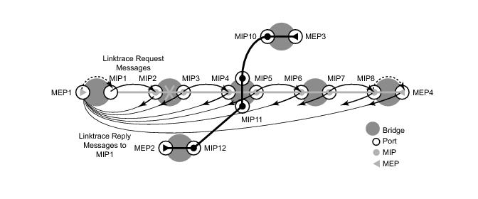
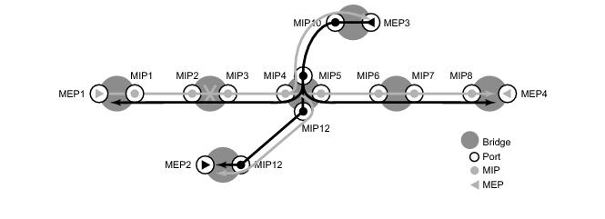
A linktrace message is originated by an MEP and targeted to a peer MEP in the same MA and within the same MD level (Figure 36). Its function is similar to IP traceroute.
Traces a specific MAC address through the service. The peer MEP responds with a linktrace reply message after successful inspection of the linktrace message. The MIPs along the path also process the linktrace message and respond with linktrace replies to the originating MEP if the received linktrace message that has a TTL greater than 1 and forward the linktrace message if a look up of the target MAC address in the Layer 2 FIB is successful. The originating MEP shall expect to receive multiple linktrace replies and from processing the linktrace replies, it can put together the route to the target bridge.
# oam eth-cfm linktrace d0:0d:1e:01:01:02 mep 101 domain 4 association 1
Index Ingress Mac Egress Mac Relay Action
----- -------------------- -------------------- ---------- ----------
1 00:00:00:00:00:00 D0:0D:1E:01:01:01 n/a forward
2 D0:0D:1E:01:01:02 00:00:00:00:00:00 n/a none
----- -------------------- -------------------- ---------- ----------
No more responses received in the last 6 seconds.
# oam eth-cfm linktrace d0:0d:1e:00:01:02 mep 101 domain 4 association 1
Index Ingress Mac Egress Mac Relay Action
----- -------------------- -------------------- ---------- ----------
1 00:00:00:00:00:00 D0:0D:1E:01:01:01 n/a forward
2 D0:0D:1E:01:01:02 D0:0D:1E:00:01:02 n/a terminate
----- -------------------- -------------------- ---------- ----------
No more responses received in the last 6 seconds.
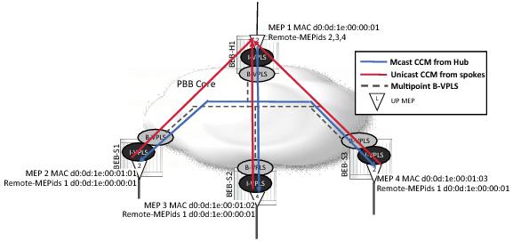
|
•
|
CCM transmit interval: 10ms, 100ms, 1s, 10s 60s, 600s. Default: 10s. Sub-second, or fast CC requires a ESS-7/ESS-12 and SR-7/SR-12 with a minimum SF/CPM-3, and with only a limited number supported on SF/CPM-1 and SF/CPM-2. When configuring MEPs with sub-second CCM intervals, bandwidth consumption must be taken into consideration. Each CCM PDU is approximately 100 bytes (800 bits). Taken individually, this is a small value. However, the bandwidth consumption increases rapidly as multiple MEPs are configured with 10ms timers, 100 packets per second.
|
You can use the optional ccm-tlv-ignore command to ignore the reception of interface-status and port-status TLVs in the ETH-CCM PDU on Facility MEPs (Port, LAG, QinQ Tunnel and Router). No processing is performed on the ignored ETH-CCM TLVs values.
Any TLV that is ignored is reported as absent for that remote peer and the values in the TLV do not have an impact on the ETH-CFM state machine. This the same behavior as if the remote MEP never included the ignored TLVs in the ETH-CCM PDU. If the TLV is not properly formed, the CCM PDU will fail the packet parsing process, which will cause it to be discarded and a defect condition will be raised.
Config>eth-cfm# info
----------------------------------------------
domain 4 format none level 4
association 1 format icc-based name "04-0000000102"
bridge-identifier 100
exit
ccm-interval 1
remote-mepid 102
exit
exit
----------------------------------------------
config>eth-cfm# info
----------------------------------------------
domain 4 format none level 4
association 1 format icc-based name "04-0000000102"
bridge-identifier 100
exit
ccm-interval 1
remote-mepid 101
exit
exit
----------------------------------------------
config>service>epipe# info
----------------------------------------------
sap 1/1/2:100.31 create
eth-cfm
mip mac D0:0D:1E:01:01:01
exit
exit
sap 1/1/10:100.31 create
eth-cfm
mep 101 domain 4 association 1 direction up
ccm-enable
mac-address d0:0d:1e:00:01:01
no shutdown
exit
exit
exit
no shutdown
----------------------------------------------
config>service>epipe# info
----------------------------------------------
sap 1/1/2:100.31 create
eth-cfm
mip mac D0:0D:1E:01:01:02
exit
exit
sap 1/1/10:100.31 create
eth-cfm
mep 102 domain 4 association 1 direction up
ccm-enable
mac-address d0:0d:1e:00:01:02
no shutdown
exit
exit
exit
no shutdown
----------------------------------------------
No defect conditions are raised. The Defect column in the first display is clear and the
Defect Flags is the second display is also clear.
show eth-cfm cfm-stack-table
===============================================================================
CFM Stack Table Defect Legend:
R = Rdi, M = MacStatus, C = RemoteCCM, E = ErrorCCM, X = XconCCM, A = AisRx
===============================================================================
CFM SAP Stack Table
===============================================================================
Sap Lvl Dir Md-index Ma-index MepId Mac-address Defect
-------------------------------------------------------------------------------
1/1/2:100.31 4 Both 4 2 MIP d0:0d:1e:01:01:01 ------
1/1/10:100.31 4 Up 4 1 101 d0:0d:1e:00:01:01 ------
===============================================================================
show eth-cfm mep 101 domain 4 association 1
===============================================================================
Eth-Cfm MEP Configuration Information
===============================================================================
Md-index : 4 Direction : Up
Ma-index : 1 Admin : Enabled
MepId : 101 CCM-Enable : Enabled
IfIndex : 35979264 PrimaryVid : 2031716
Description : (Not Specified)
FngState : fngReset ControlMep : False
LowestDefectPri : macRemErrXcon HighestDefect : none
Defect Flags : None
Mac Address : d0:0d:1e:00:01:01 ControlMep : False
CcmLtmPriority : 7
CcmTx : 1639 CcmSequenceErr : 0
Fault Propagation : disabled FacilityFault : n/a
MA-CcmInterval : 1 MA-CcmHoldTime : 0ms
Eth-1Dm Threshold : 3(sec) MD-Level : 4
Eth-Ais: : Disabled
Eth-Tst: : Disabled
Redundancy:
MC-LAG State : n/a
CcmLastFailure Frame:
None
XconCcmFailure Frame:
None
===============================================================================
The all-remote-mepids is the appropriate command to show the details for each configured peer, including the MAC address.
show eth-cfm mep 101 domain 4 association 1 all-remote-mepids
============================================================================
Eth-CFM Remote-Mep Table
============================================================================
R-mepId Rx CC Rx Rdi Port-Tlv If-Tlv Peer Mac Addr CCM status since
----------------------------------------------------------------------------
102 True False Up Up d0:0d:1e:00:01:02 02/02/2011 13:37:42
============================================================================
The grace announcement using ETH-VSM will continue until the upgrade or reset is completed. During an IOM soft reset ETH-CFM will not determine which peers are affected by a soft reset of a specific IOM. All remote peers will receive the ETH-VSM with the grace period announcement until the soft reset is completed. This means that all remote MEPs, regardless of location on the local node will enter a grace.
Clearing the IOM does not invoke the organizational specific TLV with the grace period announcement.
This feature is enabled by default. A system wide command is available to disable this transmission of these grace messages. Entering the no grace-tx-enable in the configuration under the eth-cfm>system context will prevent the grace announcements. If this configuration option is change from enable to disable while grace is being announced the three grace stop messages will be transmitted. Changing the state of this configuration option from disable to enable will only affect future ISSU and soft reset functions. It will have no affect on any ISSU or soft reset function that is active at the time this command was enabled.
When the ccm-hold-timer down delay-down option is configured the following calculation is used to determine the remote peer time out (3.5 times the CCM-Interval + ccm-hold-timer delay-down).
AIS configuration has two components: receive and transmit. AIS reception is enabled when the command ais-enable is configured under the MEP. The transmit function is enabled when the
client-meg-level is configured.
AIS is enabled under the service and has two parts, receive and transmit. Both of the components have their own configuration option. The ais-enable command under the SAP allows for the processing of received AIS packets at the MEP level. The
client-meg-level command is the transmit portion that generates AIS if the MEP enter a fault state. AIS is independent of the
low-priority-defect setting, so that any fault in the MEP causes AIS to be generated.
config>service>epipe# info
----------------------------------------------
sap 1/1/2:100.31 create
eth-cfm
mip mac D0:0D:1E:01:01:01
exit
exit
sap 1/1/10:100.31 create
eth-cfm
mep 101 domain 4 association 1 direction up
ais-enable
client-meg-level 5
exit
ccm-enable
mac-address d0:0d:1e:00:01:01
no shutdown
exit
exit
exit
no shutdown
----------------------------------------------
When MEP 101 enters a defect state, it starts to generate AIS out the passive side of the MEP, away from the fault. In this case, the AIS generates out sap 1/1/10:100.31 since MEP 101 is an up MEP on that SAP. The Defect Flag indicates that an RDI error state has been encountered and even though the
LowestDefectPri setting is higher than the existing defect AIS is being transmitted. The
Eth-Ais Tx Counted value is increasing, indicating that AIS is actively being sent.
# show eth-cfm mep 101 domain 4 association 1
===============================================================================
Eth-Cfm MEP Configuration Information
===============================================================================
Md-index : 4 Direction : Up
Ma-index : 1 Admin : Enabled
MepId : 101 CCM-Enable : Disabled
IfIndex : 35979264 PrimaryVid : 2031716
Description : (Not Specified)
FngState : fngReset ControlMep : False
LowestDefectPri : macRemErrXcon HighestDefect : none
Defect Flags : bDefRDICCM
Mac Address : d0:0d:1e:00:01:01 ControlMep : False
CcmLtmPriority : 7
CcmTx : 2578 CcmSequenceErr : 0
Fault Propagation : disabled FacilityFault : n/a
MA-CcmInterval : 1 MA-CcmHoldTime : 0ms
Eth-1Dm Threshold : 3(sec) MD-Level : 4
Eth-Ais: : Enabled Eth-Ais Rx Ais: : No
Eth-Ais Tx Priorit*: 7 Eth-Ais Rx Interv*: 1
Eth-Ais Tx Interva*: 1 Eth-Ais Tx Counte*: 288
Eth-Ais Tx Levels : 5
Eth-Tst: : Disabled
Redundancy:
MC-LAG State : n/a
CcmLastFailure Frame:
None
XconCcmFailure Frame:
None
===============================================================================
NODE1
config>service>epipe# info
----------------------------------------------
sap 1/1/2:100.31 create
eth-cfm
mip mac D0:0D:1E:01:01:01
exit
exit
sap 1/1/10:100.31 create
eth-cfm
mep 101 domain 4 association 1 direction up
eth-test-enable
exit
mac-address d0:0d:1e:00:01:01
no shutdown
exit
exit
exit
no shutdown
----------------------------------------------
# oam eth-cfm eth-test d0:0d:1e:00:01:02 mep 101 domain 4 association 1 data-length 1000
# oam eth-cfm eth-test d0:0d:1e:00:01:02 mep 101 domain 4 association 1 data-length 1000
# oam eth-cfm eth-test d0:0d:1e:00:01:02 mep 101 domain 4 association 1 data-length 1000
NODE2
config>service>epipe# info
----------------------------------------------
sap 1/1/2:100.31 create
eth-cfm
mip mac D0:0D:1E:01:01:02
exit
exit
sap 1/1/10:100.31 create
eth-cfm
mep 102 domain 4 association 1 direction up
eth-test-enable
exit
mac-address d0:0d:1e:00:01:02
no shutdown
exit
exit
exit
no shutdown
----------------------------------------------
# show eth-cfm mep 102 domain 4 association 1 eth-test-results
===============================================================
Eth CFM ETH-Test Result Table
===============================================================
Current Accumulate
FrameCount ErrBits ErrBits
Peer Mac Addr ByteCount CrcErrs CrcErrs
---------------------------------------------------------------
d0:0d:1e:00:01:01 3 0 0
3000 0 0
===============================================================
oam eth-cfm two-way-delay-test d0:0d:1e:00:01:02 mep 101 domain 4 association 1
Two-Way-Delay-Test Response:
Delay 2955 microseconds Variation 111 microseconds
# show eth-cfm mep 101 domain 4 association 1 two-way-delay-test
===================================================================
Eth CFM Two-way Delay Test Result Table
===================================================================
Peer Mac Addr Delay (us) Delay Variation (us)
-------------------------------------------------------------------
d0:0d:1e:00:01:02 2955 111
===================================================================
config>eth-cfm# info
----------------------------------------------
domain 3 format none level 3
association 1 format icc-based name "03-0000000100"
bridge-identifier 100
exit
ccm-interval 1
remote-mepid 101
exit
exit
----------------------------------------------
config>service>vpls# info
----------------------------------------------
stp
shutdown
exit
sap 1/1/3:100.100 create
exit
sap lag-1:100.100 create
eth-cfm
mep 100 domain 3 association 1 direction down
ccm-enable
mac-address d0:0d:1e:00:01:00
no shutdown
exit
exit
exit
no shutdown
----------------------------------------------
config>saa# info
----------------------------------------------
test "slm1"
type
eth-cfm-two-way-slm d0:0d:1e:00:01:01 mep 100 domain 3
association 1 count 100 timeout 1 interval 1
exit
continuous
no shutdown
exit
----------------------------------------------
# show saa slm1
Test Run: 183
Total number of attempts: 99
Number of requests that failed to be sent out: 0
Number of responses that were received: 48
Number of requests that did not receive any response: 50
Total number of failures: 50, Percentage: 50
(in ms) Min Max Average Jitter
Outbound : -370 -362 -366 0.432
Inbound : 363 371 367 0.308
Roundtrip : 0.000 5.93 1.38 0.496
Per test packet:
Sequence Outbound Inbound RoundTrip Result
1 0.000 0.000 0.000 Out Loss
2 0.000 0.000 0.000 Out Loss
3 0.000 0.000 0.000 Out Loss
4 0.000 0.000 0.000 Out Loss
…snip…
46 -369 370 1.28 Response Received
47 -362 363 1.42 Response Received
48 0.000 0.000 0.000 In Loss
49 0.000 0.000 0.000 In Loss
50 -362 363 1.42 Response Received
51 -362 363 1.16 Response Received
52 -362 364 1.20 Response Received
53 -362 364 1.18 Response Received
54 -363 364 1.20 Response Received
…snip…
96 -369 370 1.29 Response Received
97 -369 370 1.30 Response Received
98 0.000 0.000 0.000 Unacknowledged
99 0.000 0.000 0.000 Unacknowledged
100 0.000 0.000 0.000 Unacknowledged
===============================================================================
The following is an example of an on demand tests that and the associated output. Only single test runs are stored and can be viewed after the fact.
#oam eth-cfm two-way-slm-test d0:0d:1e:00:01:01 mep 100 domain 3 association 1 send-count
20 interval 1 timeout 1
Sending 20 packets to d0:0d:1e:00:01:01 from MEP 100/3/1 (Test-id: 588)
Sent 20 packets, 20 packets received from MEP ID 101, (Test-id: 588)
(0 out-loss, 0 in-loss, 0 unacknowledged)
# show eth-cfm mep 100 domain 3 association 1 two-way-slm-test
===============================================================================
Eth CFM Two-way SLM Test Result Table (Test-id: 588)
===============================================================================
Peer Mac Addr Remote MEP Count In Loss Out Loss Unack
-------------------------------------------------------------------------------
d0:0d:1e:00:01:01 101 20 0 0 0
===============================================================================
Setting the lowest defect priority to allDef may cause problems when fault propagation is enabled in the MEP. In this scenario, when MEP A sends CCM to MEP B with interface status down, MEP B will respond with a CCM with RDI set. If MEP A is configured to accept RDI as a fault, then it gets into a dead lock state, where both MEPs will declare fault and never be able to recover. The default lowest defect priority is DefMACstatus, which will not be a problem when interface status TLV is used. It is also very important that different Ethernet OAM strategies should not overlap the span of each other. In some cases, independent functions attempting to perform their normal fault handling can negatively impact the other. This interaction can lead to fault propagation in the direction toward the original fault, a false positive, or worse, a deadlock condition that may require the operator to modify the configuration to escape the condition. For example, overlapping Link Loss Forwarding (LLF) and ETH-CFM fault propagation could cause these issues.
Note that as stated in CFM Connectivity Fault Conditions, a fault is raised whenever a remote MEP is down (not all remote MEPs have to be down). When it is not desirable to trigger fault handling actions in some cases when a down MEP has multiple remote MEPs, operators can disable fault propagation for the MEP.
In order to preserve system resources, specifically memory, the operator should only store summarized history results. By default, summary results are stored for tests configured with sub second probe intervals, or a probe count above 100 or is written to a file. By default, per probe information will be stored for test configured with an interval of one second or above counters, and probe counts of 100 or less and is not written to a file. The operator may choose to override these defaults using the probe-history {keep|drop|auto} option. The “auto” option sets the defaults above. The other options override the default retention schemes based on the operator requirements, per probe retention “keep” or summary only information “drop”. The probe data can be viewed using the “show saa test” command. If the per probe information is retained, this probe data is available at the completion of the test run. The summary data is updated throughout the test run. The overall memory system usage is available using the “show system memory-pools” command. The OAM entry represents the overall memory usage. This includes the history data stored for SAA tests. A “clear saa
testname” option is available to release the memory and flush the test results.
saa>test# info
----------------------------------------------
description "Two Way ETH-DDM To MEP 327 From MEP 325"
type
eth-cfm-two-way-delay d0:0d:1e:00:00:27 mep 325 domain 12 association 300
count 900 interval 1
exit
trap-gen
probe-fail-enable
probe-fail-threshold 10
exit
accounting-policy 1
continuous
no shutdown
config>log# info
----------------------------------------------
file-id 1
location cf3:
rollover 60 retention 24
exit
accounting-policy 1
description "SAA XML File"
record saa
collection-interval 15
to file 1
no shutdown
exit
show saa "saa-dmm-1"
===============================================================================
SAA Test Information
===============================================================================
Test name : saa-dmm-1
Owner name : TiMOS CLI
Description : Two Way ETH-DDM To MEP 327 From MEP 325
Accounting policy : 1
Continuous : Yes
Administrative status : Enabled
Test type : eth-cfm-two-way-delay d0:0d:1e:00:00:27 mep
325 domain 12 association 300 count 900
interval 1
Trap generation : probe-fail-enable probe-fail-threshold 10
Probe History : auto (drop)
Test runs since last clear : 3
Number of failed test runs : 0
Last test result : Success
-------------------------------------------------------------------------------
Threshold
Type Direction Threshold Value Last Event Run #
-------------------------------------------------------------------------------
Jitter-in Rising None None Never None
Falling None None Never None
Jitter-out Rising None None Never None
Falling None None Never None
Jitter-rt Rising None None Never None
Falling None None Never None
Latency-in Rising None None Never None
Falling None None Never None
Latency-out Rising None None Never None
Falling None None Never None
Latency-rt Rising None None Never None
Falling None None Never None
Loss-in Rising None None Never None
Falling None None Never None
Loss-out Rising None None Never None
Falling None None Never None
Loss-rt Rising None None Never None
Falling None None Never None
===============================================================================
Test Run: 18
Total number of attempts: 900
Number of requests that failed to be sent out: 0
Number of responses that were received: 900
Number of requests that did not receive any response: 0
Total number of failures: 0, Percentage: 0
(in ms) Min Max Average Jitter
Outbound : -29.3 -28.6 -28.9 0.000
Inbound : 28.7 29.3 29.0 0.000
Roundtrip : 0.069 0.077 0.073 0.000
Per test packet:
Test Run: 19
Total number of attempts: 900
Number of requests that failed to be sent out: 0
Number of responses that were received: 900
Number of requests that did not receive any response: 0
Total number of failures: 0, Percentage: 0
(in ms) Min Max Average Jitter
Outbound : -29.9 -29.3 -29.6 0.000
Inbound : 29.3 30.0 29.7 0.001
Roundtrip : 0.069 0.080 0.073 0.001
Per test packet:
Test Run: 20
Total number of attempts: 181
Number of requests that failed to be sent out: 0
Number of responses that were received: 181
Number of requests that did not receive any response: 0
Total number of failures: 0, Percentage: 0
(in ms) Min Max Average Jitter
Outbound : -30.0 -29.9 -30.0 0.001
Inbound : 30.0 30.1 30.0 0.000
Roundtrip : 0.069 0.075 0.072 0.001
Per test packet:
===============================================================================
show test-oam oam-config-summary: Provides information about the configured tests.
show test-oam oam-perf: Provides the transmit (launched form me) rate information and remotely launched test receive rate on the local network element.
clear test-oam oam-perf: Provides the ability to clear the test oam performance stats for a current view of the different rates in the oam-perf command above.
monitor test-oam oam-perf: Makes use of the monitor command to provide time sliced performance stats for test oam functions.