|
1.
|
Sub-ring to a major/sub ring with a virtual channel — In this case, a data service on the major/sub ring is created which is used to forward the R-APS messages for the sub-ring over the major/sub ring, between the interconnection points of the sub-ring to the major/sub ring. This allows the sub-ring to operate as a fully connected ring and is mandatory if the sub-ring connects two major/sub rings since the virtual channel is the only mechanism that the sub-rings can use to exchange control messages. It also could improve failover times if the sub-ring was large as it provides two paths on the sub-ring interconnection nodes to propagate the fault indication around the sub-ring, whereas without a virtual channel the fault indication may need to traverse the entire sub-ring. Each sub-ring requires its own data service on the major/sub ring for the virtual channel.
|
|
3.
|
Sub-ring to a VPLS service — This is similar to (2) above but uses a VPLS service instead of a major ring. In this option, sub-ring failures can initiate the sending of an LDP MAC flush message into the VPLS service when spoke or MPLS mesh SDPs are used in the VPLS service.
|
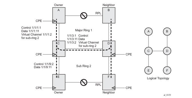
Figure 293 shows a ring of six nodes, with a major ring (regular Ethernet ring) on the top four nodes and a sub-ring on the bottom. A major ring is a fully connected ring. A sub-ring is a partial ring that depends on a major ring or a VPLS topology for part of the ring interconnect. Two major rings can be connected by a single sub-ring or a sub-ring can support other sub-rings.
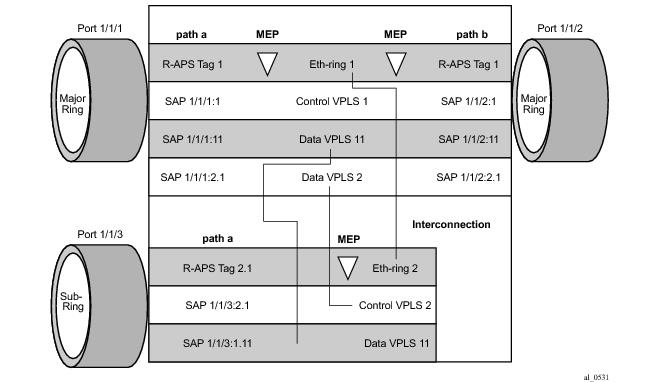
Figure 295 depicts the major ring and sub-ring interconnection components:
In Figure 295, the inner tag values are kept the same for clarity but in fact any encapsulation that is consistent with the next ring link will work. In other words, ring SAPs can perform VLAN ID translation and even when connecting a sub-ring to a major ring. This also means that other ports may reuse the same tags when connecting independent services.
configure eth-ring <ring-index>
ccm-hold-time { [down <down-timeout>] [up <up-timeout>] }
compatible-version {1|2}
description <description-string>
guard-time <time>
node-id <xx:xx:xx:xx:xx:xx or xx-xx-xx-xx-xx-xx>
path {a|b} [ {<port-id>|<lag-id>]} raps-tag <qtag[.<qtag>] ]
description <description-string>
eth-cfm
mep <mep-id> domain <md-index> association <ma-index>
...
rpl-end
shutdown
revert-time <time>
rpl-node {owner|nbr}
shutdown
sub-ring {virtual-link|non-virtual-link}
interconnect [ring-id <ring-index>|vpls]
propagate-topology-change
|
→
|
down — This command specifies the timer which controls the delay between detecting that ring path is down and reporting it to the G.8032 protection module. If a non-zero value is configured, the system will wait for the time specified in the value parameter before reporting it to the G.8032 protection module. Note that this parameter applies only to ring path CCM. It does not apply to the ring port link state. To dampen ring port link state transitions, use the hold-time parameter from the physical member port. This is useful if the underlying path between two nodes is going across an optical system which implements its own protection.
|
|
→
|
up — This command specifies the timer which controls the delay between detecting that ring path is up and reporting it to the G.8032 protection module. If a non-zero value is configured, the system will wait for the time specified in the value parameter before reporting it to the G.8032 protection module. Note that this parameter applies only to ring path CCM. It does not apply to the member port link state. To dampen member port link state transitions, use the hold-time parameter from the physical member port.
|
|
•
|
compatible-version — This command configures eth-ring compatibility version for the G.8032 state machine and messages. The default is version 2 (ITU G.8032v2) and all 7x50 systems use version 2. If there is a need to interwork with third party devices that only support version 1, this can be set to version 1 allowing the reception of version 1 PDUs. Note that version 2 is encoded as 1 in the R-APS messages. Compatibility allows the reception of version 1 (encoded as 0) R-APS PDUs but, as per the G.8032 specification, higher versions are ignored on reception. For the SR/ESS, messages are always originated with version 2. Therefore if a third party switch supported version 3 (encoded as 2) or higher interworking is also supported provided the other switch is compatible with version 2.
|
|
•
|
description < description-string> — This configures a text string, up to 80 characters, which can be used to describe the use of the eth-ring.
|
|
•
|
guard-time < time> — The forwarding method, in which R-APS messages are copied and forwarded at every Ethernet ring node, can result in a message corresponding to an old request, that is no longer relevant, being received by Ethernet ring nodes. Reception of an old R-APS message may result in erroneous ring state interpretation by some Ethernet ring nodes. The guard timer is used to prevent Ethernet ring nodes from acting upon outdated R-APS messages and prevents the possibility of forming a closed loop. Messages are not forwarded when the guard-timer is running. Values: [1..20] in deciseconds - Default: 5 1 decisecond = 100ms
|
|
•
|
node-id <xx:xx:xx:xx:xx:xx> or <xx-xx-xx-xx-xx-xx> — This allows the node identifier to be explicitly configured. By default the chassis MAC is used. Not required in typical configurations.
|
|
•
|
path { a| b} [ {< port-id>| lag-id} raps-tag < qtag[.< qtag>] ] — This parameter defines the paths around the ring, of which there are two in different directions on the ring: an “a” path and a “b” path, except on the interconnection node where a sub-ring connects to another major/sub ring in which case there is one path (either a or b) configured together with the sub-ring command. The paths are configured on a dot1q or QinQ encapsulated access or hybrid port or a LAG with the encapsulation used for the R-APS messages on the ring. These can be either single or double tagged.
|
|
→
|
description < description-string> — This configures a text string, up to 80 characters, which can be used to describe the use of the path.
|
|
→
|
eth-cfm — Configures the associated Ethernet CFM parameters.
|
|
−
|
mep < mep-id> domain < md-index> association < ma-index> — The MEP defined under the path is used for the G.8032 protocol messages, which are based on IEEE 802.1ag/Y.1731 CFM frames.
|
|
→
|
rpl-end — When configured, this path is expected to be one end of the RPL. This parameter must be configured in conjunction with the rpl-node.
|
|
→
|
shutdown — This command shuts down the path.
|
|
•
|
revert-time < time> — This command configures the revert time for an Eth-Ring. Revert time is the time that the RPL will wait before returning to the blocked state. Configuring no revert-time disables reversion, effectively setting the revert-time to zero. Values: [60..720] in seconds - Default: 300
|
|
•
|
rpl-node { owner| nbr} — A node can be designated as either the owner of the RPL, in which case this node is responsible for the RPL, or the nbr, in which case this node is expected to be the neighbor to the RPL owner across the RPL. The nbr is optional and is included to be compliant with the specification. This parameter must be configured in conjunction with the rpl-end command. On a sub-ring without virtual channel it is mandatory to configure sub-ring non-virtual-link on all nodes on the sub-ring to ensure propagation of the R-APS messages around the sub-ring.
|
|
•
|
shutdown — This command shuts down the ring.
|
|
•
|
sub-ring { virtual-link| non-virtual-link} — This command is configured on the interconnection node between the sub-ring and its major/sub ring to indicate that this ring is a sub-ring. The parameter specifies whether it uses a virtual link through the major/sub ring for the R-APS messages or not. A ring configured as a sub-ring can only be configured with a single path.
|
|
→
|
interconnect [ ring-id < ring-index>| vpls] — A sub-ring connects to either another ring or a VPLS service. If it connects to another ring (either a major ring or another sub-ring), the ring identifier must be specified and the ring to which it connects must be configured with both a path “a” and a path “b”, meaning that it is not possible to connect a sub-ring to another sub-ring on an interconnection node. Alternatively, the vpls parameter is used to indicate the sub-ring connects to a VPLS service. Interconnection using a VPLS service requires the sub-ring to be configured with non-virtual-link.
|
|
−
|
propagate-topology-change — If a topology change event happens in the sub-ring, it can be optionally propagated with the use of this parameter to either the major/sub-ring it is connected to, using R-APS messages, or to the LDP VPLS SDP peers using an LDP “flush-all-from-me” message if the sub-ring is connected to a VPLS service.
|
*A:PE-1# configure port 1/1/1 ethernet mode access
*A:PE-1# configure port 1/1/2 ethernet mode access
*A:PE-1# configure port 1/1/3 ethernet mode access
*A:PE-1# configure port 1/1/1 ethernet encap-type qinq
*A:PE-1# configure port 1/1/2 ethernet encap-type qinq
*A:PE-1# configure port 1/1/3 ethernet encap-type qinq
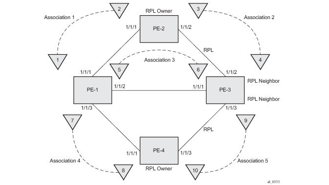
Figure 297 shows the details of the MEPs and their associations configured when both the major and sub rings are used. Note the associations only need to be pair wise unique but for clarity five unique associations are used. Also, any name format can be used but it must be consistent on both adjacent nodes.
*A:PE-1>config>eth-cfm# info
----------------------------------------------
domain 1 format none level 2
association 1 format icc-based name "1000000000001"
ccm-interval 1
remote-mepid 2
exit
association 3 format icc-based name "1000000000003"
ccm-interval 1
remote-mepid 6
exit
association 4 format icc-based name "1000000000004"
ccm-interval 1
remote-mepid 8
exit
exit
*A:PE-2>config>eth-cfm# info
----------------------------------------------
domain 1 format none level 2
association 1 format icc-based name "1000000000001"
ccm-interval 1
remote-mepid 1
exit
association 2 format icc-based name "1000000000002"
ccm-interval 1
remote-mepid 4
exit
exit
exit
*A:PE-4>config>eth-cfm# info
----------------------------------------------
domain 1 format none level 2
association 4 format icc-based name "1000000000004"
ccm-interval 1
remote-mepid 7
exit
association 5 format icc-based name "1000000000005"
ccm-interval 1
remote-mepid 9
exit
exit
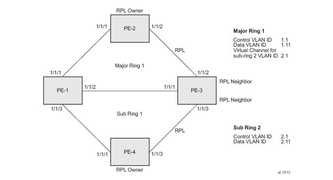
Two paths must be configured to form a ring. In this example, VLAN tag 1.1 is used as control channel for R-APS signaling for the major ring (ring 1) on the ports shown in Figure 296 using the ETH CFM information shown in
Figure 297. The revert-time is set to its minimum value and CCM messages are enabled on the MEP. The
control-mep parameter is required to indicate that this MEP is used for ring R-APS messages.
*A:PE-1>config# eth-ring 1
*A:PE-1>config>eth-ring# info
----------------------------------------------
description "Ethernet Ring 1"
revert-time 60
path a 1/1/1 raps-tag 1.1
description "Ethernet Ring : 1 Path : pathA"
eth-cfm
mep 1 domain 1 association 1
ccm-enable
control-mep
no shutdown
exit
exit
no shutdown
exit
path b 1/1/2 raps-tag 1.1
description "Ethernet Ring : 1 Path : pathB"
eth-cfm
mep 5 domain 1 association 3
ccm-enable
control-mep
no shutdown
exit
exit
no shutdown
exit
no shutdown
*A:PE-1>config>eth-ring>path# no shutdown
INFO: ERMGR #1001 Not permitted - must configure eth-cfm MEP first
*A:PE-2# configure eth-ring 1
*A:PE-2>config>eth-ring# info
----------------------------------------------
description "Ethernet Ring 1"
revert-time 60
rpl-node owner
path a 1/1/1 raps-tag 1.1
description "Ethernet Ring : 1 Path : pathA"
eth-cfm
mep 2 domain 1 association 1
ccm-enable
control-mep
no shutdown
exit
exit
no shutdown
exit
path b 1/1/2 raps-tag 1.1
description "Ethernet Ring : 1 Path : pathB"
rpl-end
eth-cfm
mep 3 domain 1 association 2
ccm-enable
control-mep
no shutdown
exit
exit
no shutdown
exit
no shutdown
*A:PE-2>config>eth-ring>path# rpl-end
INFO: ERMGR #1001 Not permitted - path-type rpl-end is not consistent with eth-ring 'rpl-node' type
*A:PE-3>config>eth-ring# info
----------------------------------------------
description "Ethernet Ring 1"
revert-time 60
rpl-node nbr
path a 1/1/1 raps-tag 1.1
description "Ethernet Ring : 1 Path : pathA"
eth-cfm
mep 6 domain 1 association 3
ccm-enable
control-mep
no shutdown
exit
exit
no shutdown
exit
path b 1/1/2 raps-tag 1.1
description "Ethernet Ring : 1 Path : pathB"
rpl-end
eth-cfm
mep 4 domain 1 association 2
ccm-enable
control-mep
no shutdown
exit
exit
no shutdown
exit
no shutdown
Ring nodes PE-1, PE-3 and PE-4 have a sub-ring. The sub-ring attaches to the major ring (ring 1). The sub-ring in this case will use a virtual-link. The interconnection ring instance identifier
(ring-id) is specified and
propagate-topology-change indicates that sub-ring flushing will be propagated to the major ring. Only one path is specified since the other path is not required at an interconnection node. Sub-rings are almost identical to major rings in operation except that sub-rings send MAC flushes towards their connected ring (either a major or sub ring). Major or sub rings never send MAC flushes to their sub-rings. Therefore a couple of sub-rings connected to a major ring can cause MACs to flush on the major ring but the major ring will not propagate a sub-ring MAC flush to other sub-rings.
*A:PE-1>config# eth-ring 2
*A:PE-1>config>eth-ring# info
----------------------------------------------
description "Ethernet Sub-ring 2 on Ring 1"
revert-time 60
sub-ring virtual-link
interconnect ring-id 1
propagate-topology-change
exit
exit
path a 1/1/3 raps-tag 2.1
description "Ethernet Ring : 2 Path : pathA"
eth-cfm
mep 7 domain 1 association 4
ccm-enable
control-mep
no shutdown
exit
exit
no shutdown
exit
no shutdown
*A:PE-3>config# eth-ring 2
*A:PE-3>config>eth-ring# info
----------------------------------------------
description "Ethernet Sub-ring 2 on Ring 1"
revert-time 60
rpl-node nbr
sub-ring virtual-link
interconnect ring-id 1
propagate-topology-change
exit
exit
path a 1/1/3 raps-tag 2.1
description "Ethernet Ring : 2 Path : pathA"
rpl-end
eth-cfm
mep 9 domain 1 association 5
ccm-enable
control-mep
no shutdown
exit
exit
no shutdown
exit
no shutdown
*A:PE-4>config# eth-ring 2
*A:PE-4>config>eth-ring# info
----------------------------------------------
description "Ethernet Ring : 2"
revert-time 60
rpl-node owner
path a 1/1/1 raps-tag 2.1
description "Ethernet Ring : 2 : pathA"
eth-cfm
mep 8 domain 1 association 4
ccm-enable
control-mep
no shutdown
exit
exit
no shutdown
exit
path b 1/1/3 raps-tag 2.1
description "Ethernet Ring : 2 : pathB"
rpl-end
eth-cfm
mep 10 domain 1 association 5
ccm-enable
control-mep
no shutdown
exit
exit
no shutdown
exit
no shutdown
*A:PE-1# show eth-ring 1
===============================================================================
Ethernet Ring 1 Information
===============================================================================
Description : Ethernet Ring 1
Admin State : Up Oper State : Down
Node ID : d8:30:ff:00:00:00
Guard Time : 5 deciseconds RPL Node : rplNone
Max Revert Time : 60 seconds Time to Revert : N/A
CCM Hold Down Time : 0 centiseconds CCM Hold Up Time : 20 deciseconds
Compatible Version : 2
APS Tx PDU : Request State: 0xB
Sub-Code : 0x0
Status : 0x20 ( BPR )
Node ID : d8:30:ff:00:00:00
Defect Status :
Sub-Ring Type : none
-------------------------------------------------------------------------------
Ethernet Ring Path Summary
-------------------------------------------------------------------------------
Path Port Raps-Tag Admin/Oper Type Fwd State
-------------------------------------------------------------------------------
a 1/1/1 1.1 Up/Down normal blocked
b 1/1/2 1.1 Up/Down normal blocked
===============================================================================
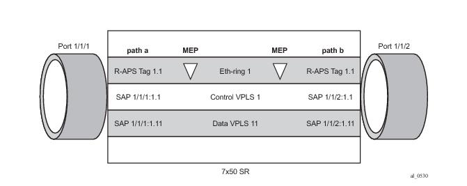
Path “a” and “b” configured in the eth-ring must be added as SAPs into a VPLS service (standard VPLS) using the eth-ring parameter. The SAP encapsulation values must match the values of the
raps-tag configured for the associated path.
*A:PE-1>config>service# vpls 1
*A:PE-1>config>service>vpls# info
----------------------------------------------
description "Control VID 1.1 for Ring 1 Major Ring"
stp
shutdown
exit
sap 1/1/1:1.1 eth-ring 1 create
stp
shutdown
exit
exit
sap 1/1/2:1.1 eth-ring 1 create
stp
shutdown
exit
exit
no shutdown
*A:PE-2>config>service# vpls 1
*A:PE-2>config>service>vpls# info
----------------------------------------------
description "Control VID 1.1 for Ring 1 Major Ring"
stp
shutdown
exit
sap 1/1/1:1.1 eth-ring 1 create
stp
shutdown
exit
exit
sap 1/1/2:1.1 eth-ring 1 create
stp
shutdown
exit
exit
no shutdown
*A:PE-3>config>service# vpls 1
*A:PE-3>config>service>vpls# info
----------------------------------------------
description "Control VID 1.1 for Ring 1 Major Ring"
stp
shutdown
exit
sap 1/1/1:1.1 eth-ring 1 create
stp
shutdown
exit
exit
sap 1/1/2:1.1 eth-ring 1 create
stp
shutdown
exit
exit
no shutdown
Note that you cannot add a normal SAP or SDP in a control channel VPLS, only SAPs with an eth-ring parameter can be added. Trying to add a SAP without this parameter into a control channel VPLS will result in the message below being displayed.
*A:PE-1>config>service>vpls# sap 1/1/7:1.1 create
MINOR: SVCMGR #1321 Service contains an Ethernet ring control SAP
*A:PE-1>config>service# vpls 2
*A:PE-1>config>service>vpls# info
----------------------------------------------
description "Control/Virtual Channel VID 2.1 for Ring 2"
split-horizon-group "shg-ring2" create
exit
stp
shutdown
exit
sap 1/1/1:2.1 split-horizon-group "shg-ring2" eth-ring 1 create
description "Ring 2 Interconnection using Ring 1"
stp
shutdown
exit
exit
sap 1/1/2:2.1 split-horizon-group "shg-ring2" eth-ring 1 create
description "Ring 2 Interconnection using Ring 1"
stp
shutdown
exit
exit
sap 1/1/3:2.1 eth-ring 2 create
stp
shutdown
exit
exit
no shutdown
*A:PE-2>config>service>vpls# info
----------------------------------------------
description "Virtual Channel VID 2.1 for Ring 2"
stp
shutdown
exit
sap 1/1/1:2.1 eth-ring 1 create
stp
shutdown
exit
exit
sap 1/1/2:2.1 eth-ring 1 create
stp
shutdown
exit
exit
no shutdown
*A:PE-3>config>service# vpls 2
*A:PE-3>config>service>vpls# info
----------------------------------------------
description "Control/Virtual Channel VID 2.1 for Ring 2"
split-horizon-group "shg-ring2" create
exit
stp
shutdown
exit
sap 1/1/1:2.1 split-horizon-group "shg-ring2" eth-ring 1 create
stp
shutdown
exit
exit
sap 1/1/2:2.1 split-horizon-group "shg-ring2" eth-ring 1 create
stp
shutdown
exit
exit
sap 1/1/3:2.1 eth-ring 2 create
stp
shutdown
exit
exit
no shutdown
*A:PE-4>config>service# vpls 2
*A:PE-4>config>service>vpls# info
----------------------------------------------
description "Control VID 2.1 for Ring 2 Sub-ring"
stp
shutdown
exit
sap 1/1/1:2.1 eth-ring 2 create
stp
shutdown
exit
exit
sap 1/1/3:2.1 eth-ring 2 create
stp
shutdown
exit
exit
no shutdown
*A:PE-1# show eth-ring status
===============================================================================
Ethernet Ring (Status information)
===============================================================================
Ring Admin Oper Path Information MEP Information
ID State State Path Tag State Ctrl-MEP CC-Intvl Defects
-------------------------------------------------------------------------------
1 Up Up a - 1/1/1 1.1 Up Yes 1 -----
b - 1/1/2 1.1 Up Yes 1 -----
2 Up Up a - 1/1/3 2.1 Up Yes 1 -----
b - N/A - - - -----
===============================================================================
Ethernet Tunnel MEP Defect Legend:
R = Rdi, M = MacStatus, C = RemoteCCM, E = ErrorCCM, X = XconCCM
*A:PE-1#
*A:PE-1# show eth-ring
===============================================================================
Ethernet Rings (summary)
===============================================================================
Ring Int Admin Oper Paths Summary Path States
ID ID State State a b
-------------------------------------------------------------------------------
1 - Up Up a - 1/1/1 1.1 b - 1/1/2 1.1 U U
2 1 Up Up a - 1/1/3 2.1 b - Not configured U -
===============================================================================
Ethernet Ring Summary Legend: B - Blocked U - Unblocked
*A:PE-1#
*A:PE-1# show eth-ring 1
===============================================================================
Ethernet Ring 1 Information
===============================================================================
Description : Ethernet Ring 1
Admin State : Up Oper State : Up
Node ID : d8:30:ff:00:00:00
Guard Time : 5 deciseconds RPL Node : rplNone
Max Revert Time : 60 seconds Time to Revert : N/A
CCM Hold Down Time : 0 centiseconds CCM Hold Up Time : 20 deciseconds
Compatible Version : 2
APS Tx PDU : N/A
Defect Status :
Sub-Ring Type : none
-------------------------------------------------------------------------------
Ethernet Ring Path Summary
-------------------------------------------------------------------------------
Path Port Raps-Tag Admin/Oper Type Fwd State
-------------------------------------------------------------------------------
a 1/1/1 1.1 Up/Up normal unblocked
b 1/1/2 1.1 Up/Up normal unblocked
===============================================================================
*A:PE-1#
*A:PE-2# show eth-ring 1
===============================================================================
Ethernet Ring 1 Information
===============================================================================
Description : Ethernet Ring 1
Admin State : Up Oper State : Up
Node ID : d8:31:ff:00:00:00
Guard Time : 5 deciseconds RPL Node : rplOwner
Max Revert Time : 60 seconds Time to Revert : N/A
CCM Hold Down Time : 0 centiseconds CCM Hold Up Time : 20 deciseconds
Compatible Version : 2
APS Tx PDU : Request State: 0x0
Sub-Code : 0x0
Status : 0xA0 ( RB BPR )
Node ID : d8:31:ff:00:00:00
Defect Status :
Sub-Ring Type : none
-------------------------------------------------------------------------------
Ethernet Ring Path Summary
-------------------------------------------------------------------------------
Path Port Raps-Tag Admin/Oper Type Fwd State
-------------------------------------------------------------------------------
a 1/1/1 1.1 Up/Up normal unblocked
b 1/1/2 1.1 Up/Up rplEnd blocked
===============================================================================
*A:PE-2#
Note that PE-2 is the RPL owner with port 1/1/2 as an RPL end, which is blocked as expected. The revert-time is also shown to be the configured value. Detailed information is shown relating to the R-APS PDUs being transmitted on this ring as this node is the RPL owner.
*A:PE-3# show eth-ring 1
===============================================================================
Ethernet Ring 1 Information
===============================================================================
Description : Ethernet Ring 1
Admin State : Up Oper State : Up
Node ID : d8:32:ff:00:00:00
Guard Time : 5 deciseconds RPL Node : rplNeighbor
Max Revert Time : 60 seconds Time to Revert : N/A
CCM Hold Down Time : 0 centiseconds CCM Hold Up Time : 20 deciseconds
Compatible Version : 2
APS Tx PDU : N/A
Defect Status :
Sub-Ring Type : none
-------------------------------------------------------------------------------
Ethernet Ring Path Summary
-------------------------------------------------------------------------------
Path Port Raps-Tag Admin/Oper Type Fwd State
-------------------------------------------------------------------------------
a 1/1/1 1.1 Up/Up normal unblocked
b 1/1/2 1.1 Up/Up rplEnd blocked
===============================================================================
*A:PE-3#
*A:PE-1# show eth-ring 2
===============================================================================
Ethernet Ring 2 Information
===============================================================================
Description : Ethernet Sub-ring 2 on Ring 1
Admin State : Up Oper State : Up
Node ID : d8:30:ff:00:00:00
Guard Time : 5 deciseconds RPL Node : rplNone
Max Revert Time : 60 seconds Time to Revert : N/A
CCM Hold Down Time : 0 centiseconds CCM Hold Up Time : 20 deciseconds
Compatible Version : 2
APS Tx PDU : N/A
Defect Status :
Sub-Ring Type : virtualLink Interconnect-ID : 1
Topology Change : Propagate
-------------------------------------------------------------------------------
Ethernet Ring Path Summary
-------------------------------------------------------------------------------
Path Port Raps-Tag Admin/Oper Type Fwd State
-------------------------------------------------------------------------------
a 1/1/3 2.1 Up/Up normal unblocked
b - - -/- - -
===============================================================================
*A:PE-1#
*A:PE-3# show eth-ring 2
===============================================================================
Ethernet Ring 2 Information
===============================================================================
Description : Ethernet Sub-ring 2 on Ring 1
Admin State : Up Oper State : Up
Node ID : d8:32:ff:00:00:00
Guard Time : 5 deciseconds RPL Node : rplNeighbor
Max Revert Time : 60 seconds Time to Revert : N/A
CCM Hold Down Time : 0 centiseconds CCM Hold Up Time : 20 deciseconds
Compatible Version : 2
APS Tx PDU : N/A
Defect Status :
Sub-Ring Type : virtualLink Interconnect-ID : 1
Topology Change : Propagate
-------------------------------------------------------------------------------
Ethernet Ring Path Summary
-------------------------------------------------------------------------------
Path Port Raps-Tag Admin/Oper Type Fwd State
-------------------------------------------------------------------------------
a 1/1/3 2.1 Up/Up rplEnd blocked
b - - -/- - -
===============================================================================
*A:PE-3#
*A:PE-4# show eth-ring 2
===============================================================================
Ethernet Ring 2 Information
===============================================================================
Description : Ethernet Ring : 2
Admin State : Up Oper State : Up
Node ID : d8:33:ff:00:00:00
Guard Time : 5 deciseconds RPL Node : rplOwner
Max Revert Time : 60 seconds Time to Revert : N/A
CCM Hold Down Time : 0 centiseconds CCM Hold Up Time : 20 deciseconds
Compatible Version : 2
APS Tx PDU : Request State: 0x0
Sub-Code : 0x0
Status : 0xA0 ( RB BPR )
Node ID : d8:33:ff:00:00:00
Defect Status :
Sub-Ring Type : none
-------------------------------------------------------------------------------
Ethernet Ring Path Summary
-------------------------------------------------------------------------------
Path Port Raps-Tag Admin/Oper Type Fwd State
-------------------------------------------------------------------------------
a 1/1/1 2.1 Up/Up normal unblocked
b 1/1/3 2.1 Up/Up rplEnd blocked
===============================================================================
*A:PE-4#
*A:PE-1# show eth-ring 1 path a
===============================================================================
Ethernet Ring 1 Path Information
===============================================================================
Description : Ethernet Ring : 1 Path : pathA
Port : 1/1/1 Raps-Tag : 1.1
Admin State : Up Oper State : Up
Path Type : normal Fwd State : unblocked
Fwd State Change : 09/19/2014 17:45:19
Last Switch Command: noCmd
APS Rx PDU : Request State: 0x0
Sub-Code : 0x0
Status : 0xA0 ( RB BPR )
Node ID : d8:31:ff:00:00:00
===============================================================================
*A:PE-1#
*A:PE-1# show eth-ring 1 hierarchy
===============================================================================
Ethernet Ring 1 (hierarchy)
===============================================================================
Ring Int Admin Oper Paths Summary Path States
ID ID State State a b
-------------------------------------------------------------------------------
1 - Up Up a - 1/1/1 1.1 b - 1/1/2 1.1 U U
2 1 Up Up a - 1/1/3 2.1 b - Not configured U -
===============================================================================
Ethernet Ring Summary Legend: B - Blocked U - Unblocked
*A:PE-1#
*A:PE-1>config>service# vpls 11
*A:PE-1>config>service>vpls# info
----------------------------------------------
description "Data VPLS"
stp
shutdown
exit
sap 1/1/1:1.11 eth-ring 1 create
stp
shutdown
exit
exit
sap 1/1/2:1.11 eth-ring 1 create
stp
shutdown
exit
exit
sap 1/1/3:1.11 eth-ring 2 create
stp
shutdown
exit
exit
sap 1/1/9:1 create
description "Sample Customer Service SAP"
exit
no shutdown
*A:PE-2# configure service vpls 11
*A:PE-2>config>service>vpls# info
----------------------------------------------
description "Data VPLS"
stp
shutdown
exit
sap 1/1/1:1.11 eth-ring 1 create
stp
shutdown
exit
exit
sap 1/1/2:1.11 eth-ring 1 create
stp
shutdown
exit
exit
sap 1/1/9:1 create
description "Sample Customer Service SAP"
exit
no shutdown
*A:PE-4# configure service vpls 11
*A:PE-4>config>service>vpls# info
----------------------------------------------
description "Data VPLS"
stp
shutdown
exit
sap 1/1/1:1.11 eth-ring 2 create
stp
shutdown
exit
exit
sap 1/1/3:1.11 eth-ring 2 create
stp
shutdown
exit
exit
sap 1/1/9:1 create
description "Sample Customer Service SAP"
exit
no shutdown
*A:PE-1# show service sap-using eth-ring
===============================================================================
Service Access Points (Ethernet Ring)
===============================================================================
SapId SvcId Eth-Ring Path Admin Oper Blocked Control/
State State Data
-------------------------------------------------------------------------------
1/1/1:1.1 1 1 a Up Up No Ctrl
1/1/2:1.1 1 1 b Up Up No Ctrl
1/1/1:2.1 2 1 a Up Up No Ctrl
1/1/2:2.1 2 1 b Up Up No Ctrl
1/1/3:2.1 2 2 a Up Up No Ctrl
1/1/1:1.11 11 1 a Up Up No Data
1/1/2:1.11 11 1 b Up Up No Data
1/1/3:2.11 11 2 a Up Up No Data
-------------------------------------------------------------------------------
Number of SAPs : 8
===============================================================================
*A:PE-1#
*A:PE-1# show eth-cfm statistics
===============================================================================
ETH-CFM System Statistics
===============================================================================
Rx Count : 1201 Tx Count : 1066
Dropped Congestion : 0 Discarded Error : 0
AIS Currently Act : 0 AIS Currently Fail : 0
===============================================================================
=================================
ETH-CFM System Op-code Statistics
=================================
Op-code Rx Count Tx Count
---------------------------------
ccm 1018 1018
...
raps 183 48
...
---------------------------------
Total 1201 1066
=================================
*A:PE-1#
*A:PE-2# configure port 1/1/1 shutdown
2 2014/09/19 18:03:01.00 PDT WARNING: SNMP #2004 Base 1/1/1
"Interface 1/1/1 is not operational"
3 2014/09/19 18:03:01.00 PDT MINOR: ERING #2001 Base eth-ring-1
"Eth-Ring 1 path 0 changed fwd state to blocked"
4 2014/09/19 18:03:01.00 PDT MINOR: ERING #2001 Base eth-ring-1
"Eth-Ring 1 path 1 changed fwd state to unblocked"
*A:PE-2#
5 2014/09/19 18:03:01.01 PDT MAJOR: SVCMGR #2210 Base
"Processing of an access port state change event is finished and the status of a
ll affected SAPs on port 1/1/1 has been updated."
6 2014/09/19 18:03:04.33 PDT MINOR: ETH_CFM #2001 Base
"MEP 1/1/2 highest defect is now defRemoteCCM"
*A:PE-2#
For troubleshooting, the tools dump eth-ring <
ring-index> command displays path information, the internal state of the control protocol, related statistics information and up to the last 16 protocol events (including messages sent and received, and the expiration of timers). An associated
clear parameter exists
, which clears the event information in this output when the command is entered. The following is an example of the output on PE-1.
*A:PE-1# tools dump eth-ring 1
ringId 1 (Up/Up): numPaths 2 nodeId d8:30:ff:00:00:00
SubRing: none (interconnect ring 0, propagateTc No), Cnt 1
path-a, port 1/1/1 (Up), tag 1.1(Dn) status (Up/Dn/Blk)
cc (Dn/Up): Cnt 8/7 tm 001 00:27:12.220/001 00:09:23.340
state: Cnt 9 B/F 001 00:27:12.220/001 00:09:25.410, flag: 0x0
path-b, port 1/1/2 (Up), tag 1.1(Up) status (Up/Up/Fwd)
cc (Dn/Up): Cnt 4/4 tm 001 00:07:09.200/001 00:09:23.920
state: Cnt 8 B/F 001 00:07:09.200/001 00:09:26.410, flag: 0x0
FsmState= PROT, Rpl = None, revert = 60 s, guard = 5 ds
Defects =
Running Timers = PduReTx
lastTxPdu = 0xb000 Sf
path-a Normal, RxId(I)= d8:31:ff:00:00:00, rx(F)= v1-0x00a0 Nr, cmd= None
path-b Normal, RxId(I)= d8:31:ff:00:00:00, rx= v1-0xb000 Sf, cmd= None
DebugInfo: aPathSts 10, bPathSts 7, pm (set/clr) 0/0, txFlush 2
RxRaps: ok 41 nok 0 self 4, TmrExp - wtr 0(0), grd 5, wtb 0
Flush: cnt 22 (8/14/0) tm 001 00:27:12.220-001 00:27:12.220 Out/Ack 0/1
RxRawRaps: aPath 17167 bPath 147 vPath 0
Now: 001 00:28:16.500 , softReset: No - noTx 0
Seq Event RxInfo(Path: NodeId-Bytes)
state:TxInfo (Bytes) Dir pA pB Time
=== ===== ============================== ===== === === ================
015 aDn
PROT : 0xb000 Sf TxF-> Blk Fwd 001 00:07:09.190
016 bDn
PROT : 0xb020 Sf TxF-> Blk Blk 001 00:07:09.200
017 pdu B: d8:32:ff:00:00:00-0xb000 Sf
PROT : 0xb020 Sf RxF<- Blk Blk 001 00:09:22.980
018 pdu A: d8:31:ff:00:00:00-0xb000 Sf
PROT : 0xb020 Sf RxF<- Blk Blk 001 00:09:24.410
019 pdu B: d8:32:ff:00:00:00-0x0000 Nr
PROT : 0xb020 Sf Rx<-- Blk Blk 001 00:09:25.080
000 aUp
PROT : 0xb060 Sf(DNF) Tx--> Fwd Blk 001 00:09:25.410
001 bUp
PEND-G: 0x0020 Nr Tx--> Fwd Blk 001 00:09:25.910
002 pdu A: d8:31:ff:00:00:00-0x0000 Nr
PEND-G: 0x0020 Nr Rx<-- Fwd Blk 001 00:09:26.210
003 pdu B: d8:31:ff:00:00:00-0x0000 Nr
PEND-G: 0x0020 Nr Rx<-- Fwd Blk 001 00:09:26.210
004 pdu A: d8:31:ff:00:00:00-0x0000 Nr
PEND-G: 0x0020 Nr Rx<-- Fwd Blk 001 00:09:26.310
005 pdu B: d8:31:ff:00:00:00-0x0000 Nr
PEND-G: 0x0020 Nr Rx<-- Fwd Blk 001 00:09:26.310
006 pdu A: d8:31:ff:00:00:00-0x0000 Nr
PEND : 0x0020 Nr Rx<-- Fwd Blk 001 00:09:26.410
007 pdu
PEND : ----- Fwd Fwd 001 00:09:26.410
008 pdu B: d8:31:ff:00:00:00-0x0000 Nr
PEND : Rx<-- Fwd Fwd 001 00:09:26.410
009 pdu A: d8:31:ff:00:00:00-0x00a0 Nr(RB )
PEND : RxF<- Fwd Fwd 001 00:10:41.410
010 pdu
IDLE : ----- Fwd Fwd 001 00:10:41.410
011 pdu B: d8:31:ff:00:00:00-0x00a0 Nr(RB )
IDLE : Rx<-- Fwd Fwd 001 00:10:41.410
012 pdu B: d8:31:ff:00:00:00-0xb000 Sf
IDLE : RxF<- Fwd Fwd 001 00:27:09.120
013 pdu
PROT : ----- Fwd Fwd 001 00:27:09.120
014 aDn
PROT : 0xb000 Sf TxF-> Blk Fwd 001 00:27:12.220
*A:PE-1#
*A:PE-1# configure eth-ring 2
*A:PE-1>config>eth-ring# info
----------------------------------------------
description "Ethernet Sub-ring 2 on Ring 1"
revert-time 60
sub-ring non-virtual-link
interconnect ring-id 1
propagate-topology-change
exit
exit
path a 1/1/3 raps-tag 2.1
description "Ethernet Ring : 2 Path : pathA"
eth-cfm
mep 7 domain 1 association 4
ccm-enable
control-mep
no shutdown
exit
exit
no shutdown
exit
no shutdown
*A:PE-4# configure eth-ring 2
*A:PE-4>config>eth-ring# info
----------------------------------------------
description "Ethernet Ring : 2"
revert-time 60
rpl-node owner
sub-ring non-virtual-link
exit
path a 1/1/1 raps-tag 2.1
description "Ethernet Ring : 2 : pathA"
eth-cfm
mep 8 domain 1 association 4
ccm-enable
control-mep
no shutdown
exit
exit
no shutdown
exit
path b 1/1/3 raps-tag 2.1
description "Ethernet Ring : 2 : pathB"
rpl-end
eth-cfm
mep 10 domain 1 association 5
ccm-enable
control-mep
no shutdown
exit
exit
no shutdown
exit
no shutdown
*A:PE-1# show service sap-using eth-ring
===============================================================================
Service Access Points (Ethernet Ring)
===============================================================================
SapId SvcId Eth-Ring Path Admin Oper Blocked Control/
State State Data
-------------------------------------------------------------------------------
1/1/1:1.1 1 1 a Up Up No Ctrl
1/1/2:1.1 1 1 b Up Up No Ctrl
1/1/3:2.1 2 2 a Up Up No Ctrl
1/1/1:1.11 11 1 a Up Up No Data
1/1/2:1.11 11 1 b Up Up No Data
1/1/3:1.11 11 2 a Up Up No Data
-------------------------------------------------------------------------------
Number of SAPs : 6
===============================================================================
*A:PE-1#
*A:PE-1# show eth-ring 2
===============================================================================
Ethernet Ring 2 Information
===============================================================================
Description : Ethernet Sub-ring 2 on Ring 1
Admin State : Up Oper State : Up
Node ID : d8:30:ff:00:00:00
Guard Time : 5 deciseconds RPL Node : rplNone
Max Revert Time : 60 seconds Time to Revert : N/A
CCM Hold Down Time : 0 centiseconds CCM Hold Up Time : 20 deciseconds
Compatible Version : 2
APS Tx PDU : N/A
Defect Status :
Sub-Ring Type : nonVirtualLink Interconnect-ID : 1
Topology Change : Propagate
-------------------------------------------------------------------------------
Ethernet Ring Path Summary
-------------------------------------------------------------------------------
Path Port Raps-Tag Admin/Oper Type Fwd State
-------------------------------------------------------------------------------
a 1/1/3 2.1 Up/Up normal unblocked
b - - -/- - -
===============================================================================
*A:PE-1#
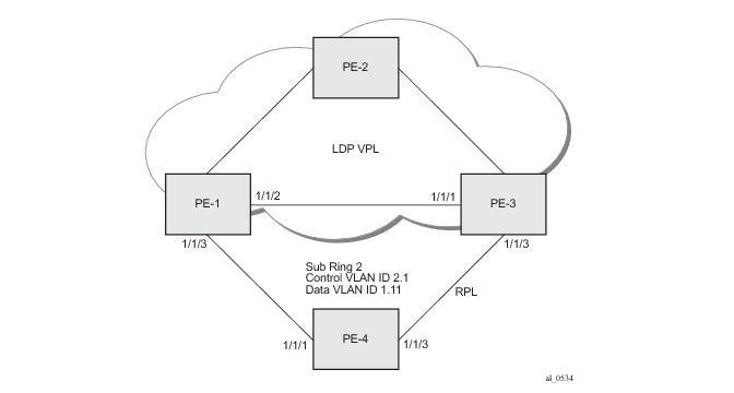
The topology for this case is shown in Figure 298. The configuration is very similar to the sub-ring with a non-virtual link described above, but ring 1 is replaced by a VPLS service using LDP signaled mesh SDPs between PE-1, PE-2 and PE-3 to create a fully meshed VPLS service. Note that either spoke or mesh SDPs using LDP could be used for the VPLS, however, only mesh SDPs have been used in this example.
*A:PE-1>config# eth-ring 2
*A:PE-1>config>eth-ring# info
----------------------------------------------
description "Ethernet Sub-ring 2 on Ring 1"
revert-time 60
sub-ring non-virtual-link
interconnect vpls
propagate-topology-change
exit
exit
path a 1/1/3 raps-tag 2.1
description "Ethernet Ring : 2 Path : pathA"
eth-cfm
mep 7 domain 1 association 4
ccm-enable
control-mep
no shutdown
exit
exit
no shutdown
exit
no shutdown
*A:PE-4# configure eth-ring 2
*A:PE-4>config>eth-ring# info
----------------------------------------------
description "Ethernet Ring : 2"
revert-time 60
rpl-node owner
sub-ring non-virtual-link
exit
path a 1/1/1 raps-tag 2.1
description "Ethernet Ring : 2 : pathA"
eth-cfm
mep 8 domain 1 association 4
ccm-enable
control-mep
no shutdown
exit
exit
no shutdown
exit
path b 1/1/3 raps-tag 2.1
description "Ethernet Ring : 2 : pathB"
rpl-end
eth-cfm
mep 10 domain 1 association 5
ccm-enable
control-mep
no shutdown
exit
exit
no shutdown
exit
no shutdown
*A:PE-1>config>service# vpls 11
*A:PE-1>config>service>vpls# info
----------------------------------------------
description "Data VPLS"
stp
shutdown
exit
sap 1/1/3:1.11 eth-ring 2 create
stp
shutdown
exit
exit
sap 1/1/9:1 create
description "Sample Customer Service SAP"
exit
mesh-sdp 2:11 create
no shutdown
exit
mesh-sdp 3:11 create
no shutdown
exit
no shutdown
*A:PE-1# show eth-ring 2
===============================================================================
Ethernet Ring 2 Information
===============================================================================
Description : Ethernet Sub-ring 2 on Ring 1
Admin State : Up Oper State : Up
Node ID : d8:30:ff:00:00:00
Guard Time : 5 deciseconds RPL Node : rplNone
Max Revert Time : 60 seconds Time to Revert : N/A
CCM Hold Down Time : 0 centiseconds CCM Hold Up Time : 20 deciseconds
Compatible Version : 2
APS Tx PDU : N/A
Defect Status :
Sub-Ring Type : nonVirtualLink Interconnect-ID : VPLS
Topology Change : Propagate
-------------------------------------------------------------------------------
Ethernet Ring Path Summary
-------------------------------------------------------------------------------
Path Port Raps-Tag Admin/Oper Type Fwd State
-------------------------------------------------------------------------------
a 1/1/3 2.1 Up/Up normal unblocked
b - - -/- - -
===============================================================================
*A:PE-1#
*A:PE-1# debug router ldp peer 192.0.2.2 packet init
*A:PE-1# debug router ldp peer 192.0.2.3 packet init
*A:PE-1#
*A:PE-1# show debug
debug
router "Base"
ldp
peer 192.0.2.2
event
exit
packet
init
exit
exit
peer 192.0.2.3
event
exit
packet
init
exit
exit
exit
exit
exit
*A:PE-1#
*A:PE-1# configure port 1/1/3 shutdown
2 2014/09/20 11:28:36.01 PDT WARNING: SNMP #2004 Base 1/1/3
"Interface 1/1/3 is not operational"
3 2014/09/20 11:28:36.01 PDT MINOR: ERING #2001 Base eth-ring-2
"Eth-Ring 2 path 0 changed fwd state to blocked"
1 2014/09/20 11:28:36.01 PDT MINOR: DEBUG #2001 Base LDP
"LDP: LDP
Send Address Withdraw packet (msgId 6799) to 192.0.2.2:0
MAC Flush (All MACs learned from me)
Service FEC PWE3: ENET(5)/11 Group ID = 0 cBit = 0
"
*A:PE-1#
2 2014/09/20 11:28:36.01 PDT MINOR: DEBUG #2001 Base LDP
"LDP: LDP
Send Address Withdraw packet (msgId 183) to 192.0.2.3:0
MAC Flush (All MACs learned from me)
Service FEC PWE3: ENET(5)/11 Group ID = 0 cBit = 0
"
4 2014/09/20 11:28:36.03 PDT MAJOR: SVCMGR #2210 Base
"Processing of an access port state change event is finished and the status of a
ll affected SAPs on port 1/1/3 has been updated."
5 2014/09/20 11:28:38.99 PDT MINOR: ETH_CFM #2001 Base
"MEP 1/4/7 highest defect is now defRemoteCCM"
3 2014/09/20 11:28:39.27 PDT MINOR: DEBUG #2001 Base LDP
"LDP: LDP
Recv Address Withdraw packet (msgId 184) from 192.0.2.3:0
"
*A:PE-1#
Operators may wish to configure rings with or without control over reversion. Reversion can be controlled by timers or the ring can be run without reversion allowing the operator to choose when the ring reverts. To change a ring topology, the manual or
force switch command may be used to block a specified ring path. A ring will still address failures when run without reversion but will not automatically revert to the RPL when resources are restored. A
clear command can be used to clear the manual or force state of a ring.
The following tools commands are available to control the state of paths on a ring.
tools perform eth-ring clear <ring-index>
tools perform eth-ring force <ring-index> path {a|b}
tools perform eth-ring manual <ring-index> path {a|b}
*A:PE-1# show eth-ring 1
===============================================================================
Ethernet Ring 1 Information
===============================================================================
Description : Ethernet Ring 1
Admin State : Up Oper State : Up
Node ID : d8:30:ff:00:00:00
Guard Time : 5 deciseconds RPL Node : rplNone
Max Revert Time : 60 seconds Time to Revert : N/A
CCM Hold Down Time : 0 centiseconds CCM Hold Up Time : 20 deciseconds
Compatible Version : 2
APS Tx PDU : N/A
Defect Status :
Sub-Ring Type : none
-------------------------------------------------------------------------------
Ethernet Ring Path Summary
-------------------------------------------------------------------------------
Path Port Raps-Tag Admin/Oper Type Fwd State
-------------------------------------------------------------------------------
a 1/1/1 1.1 Up/Up normal unblocked
b 1/1/2 1.1 Up/Up normal unblocked
===============================================================================
*A:PE-1#
*A:PE-1# tools perform eth-ring manual 1 path b
*A:PE-1# show eth-ring 1
===============================================================================
Ethernet Ring 1 Information
===============================================================================
Description : Ethernet Ring 1
Admin State : Up Oper State : Up
Node ID : d8:30:ff:00:00:00
Guard Time : 5 deciseconds RPL Node : rplNone
Max Revert Time : 60 seconds Time to Revert : N/A
CCM Hold Down Time : 0 centiseconds CCM Hold Up Time : 20 deciseconds
Compatible Version : 2
APS Tx PDU : Request State: 0x7
Sub-Code : 0x0
Status : 0x20 ( BPR )
Node ID : d8:30:ff:00:00:00
Defect Status :
Sub-Ring Type : none
-------------------------------------------------------------------------------
Ethernet Ring Path Summary
-------------------------------------------------------------------------------
Path Port Raps-Tag Admin/Oper Type Fwd State
-------------------------------------------------------------------------------
a 1/1/1 1.1 Up/Up normal unblocked
b 1/1/2 1.1 Up/Up normal blocked
===============================================================================
*A:PE-1#
*A:PE-1# tools perform eth-ring clear 1
*A:PE-1# show eth-ring 1
===============================================================================
Ethernet Ring 1 Information
===============================================================================
Description : Ethernet Ring 1
Admin State : Up Oper State : Up
Node ID : d8:30:ff:00:00:00
Guard Time : 5 deciseconds RPL Node : rplNone
Max Revert Time : 60 seconds Time to Revert : N/A
CCM Hold Down Time : 0 centiseconds CCM Hold Up Time : 20 deciseconds
Compatible Version : 2
APS Tx PDU : N/A
Defect Status :
Sub-Ring Type : none
-------------------------------------------------------------------------------
Ethernet Ring Path Summary
-------------------------------------------------------------------------------
Path Port Raps-Tag Admin/Oper Type Fwd State
-------------------------------------------------------------------------------
a 1/1/1 1.1 Up/Up normal unblocked
b 1/1/2 1.1 Up/Up normal unblocked
===============================================================================
*A:PE-1#
Both the manual and
force command block the path specified, however, the
manual command fails if there is an existing forced switch or signal fail event in the ring, as seen below. The
force command will block the port regardless of any existing ring state and there can be multiple force states simultaneously on a ring on different nodes.
*A:PE-1# tools perform eth-ring manual 1 path b
INFO: ERMGR #1001 Not permitted - The switch command is not compatible to the current state (MS), effective priority (MS) or rpl-node type (None)