For feedback and comments:
documentation.feedback@alcatel-lucent.com
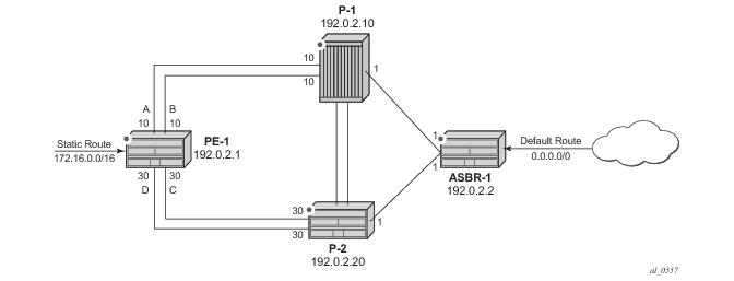
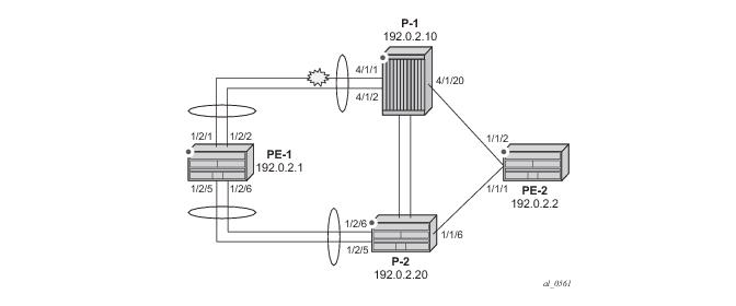
Table of Contents Previous Next Index PDF


IS-IS Link Bundling
In This Chapter
This section provides information about IS-IS link bundling.
Topics in this section include:
Applicability
This example is applicable to all 7750 SR, 7450 ESS and 7950 XRS systems with IOM3-XPs or IMMs using chassis mode D.
The configuration was tested on release 11.0.R6.
Overview
Intermediate System to Intermediate System (IS-IS) Link Bundling allows for the grouping of a number of IS-IS interfaces into a single virtual link, called an IS-IS link group. It is used in conjunction with Equal Cost Multipath (ECMP) to dynamically change the metric of parallel IS-IS links if one or more links fail or suffer some sort of performance degradation.
Figure 1.png
Figure 284: Link Bundle Schematic
Consider the network in Figure 284, where a Provider Edge router PE-1 connects to a core network comprised of two Provider (P) routers and a single Autonomous System Border Router (ASBR). The links between PE-1 and P-1, and PE-1 and P-2 are 10 Gigabit Ethernet links. The links between ASBR-1 and P-1 and P-2 are both 100Gig links. The link metrics are as shown in Figure 284.
In order to maximize the use of link bandwidth ECMP is enabled on all routers and set to a value of 2 so that IP traffic flowing between PE1 and P-1, and PE-1 and P-2, is load balanced across the two links.
A default route is injected into the ASBR-1 router and re-distributed via a policy statement into IS-IS so that traffic flowing from PE-1 to the ASBR is resolved by this route. Traffic flows between PE-1 and ASBR-1 using the path with the lowest IS-IS metric, via P-1 with a metric of 11. The second path PE-1 to ASBR-1 via P-2 has the same bandwidth but a higher IS-IS metric of 31.
Traffic in the reverse direction flows towards a user subnet described by a static route configured on PE-1 which is redistributed into IS-IS using a policy statement. Once again, the shortest path between ASBR-1 and PE-1 is via P-1, so the bi-directional traffic flow is symmetric.
If one of the links between PE-1 and P-1 fails, traffic still flows via P-1 as the IS-IS metric is unchanged, but this now has less bandwidth than the second path via P-2. It is desirable to make use of the additional bandwidth of the second path, but this requires a change in metric. This can be achieved using IS-IS link bundling.
IS-IS link bundling allows for the creation of a group of IS-IS links, where the failure of a member link allows the metric of the remaining members of the link group to be increased by an offset value.
Figure 2.png
Figure 285: Effect of Single Link Failure on Bundle Group
Using Figure 285 as an example, the links between PE-1 and P-1 are included in a bundle group. To illustrate the change in metrics, a default static route is configured on ASBR-1 and re-distributed into IS-IS, and the path to this route is monitored at PE-1. Similarly, a static route to subnet 172.16.0.0/16 is configured on PE-1 and redistributed into IS-IS and viewed on ASBR-1.
Should one of the links between PE-1 and P-1 fail, the metric of the remaining members can be increased by an offset, for example 90, so that the metric of the remaining link becomes 10+90 = 100. The IS-IS metric between PE-1 and ASBR-1 via P-1 is now 101. Note that the metric offset is applied to each remaining IS-IS interface individually and is advertised within the IS-IS database as the default cost in the TE-IS neighbors Type Length Variable (TLV).
The path between PE-1 and ASBR-1 via P-2 now has the lowest IS-IS metric, and any affected routers within the IS-IS area will try and re-route the traffic based on the new metric.
The fundamentals of this feature are:
The treatment of all member links in a link group bundle as a single virtual interface.
The increase in metric by a given offset value of each remaining individual link within the group when a failure of one or more links occurs.
The application of the offset occurs when the number of active links drops below a configured threshold.
The offset is removed when the number of active links within the link group bundle reaches the configured reversion threshold.
A link bundle is required on a router for the thresholds and offsets to apply.
Consider a second and subsequent failure where a link between PE-1 and P-2 also fails, so that there is only one active IS-IS interface between PE-1 and each of its neighboring P routers. This is shown in Figure 286.
Figure 3.png
Figure 286: Double Link Failure
In this case, the metric for the remaining link between PE-1 and P-2 can be increased by an offset value of +70 so that the IS-IS metric PE-1 to P-2 becomes 100, the same as that between PE-1 and P-1 when a link has failed.
PE-1 now sees two equal cost paths to the default route – one via P-1 and one via P-2, so there are still 2 x 10Gigabit Ethernet links across which the traffic can be load shared.
This can be summarized using the following table, where ABCD are the 4 links as per Figure 284 and link status is Up (U) or Down (D).
 
Configuration
The test topology is shown in Figure 287.
Figure 287: Test Topology
The PE-1 router configuration commands are shown below.
A:PE-1>config>router# info 
----------------------------------------------
        interface "int-PE-1-P-1-1"
            address 192.168.0.1/30
            port 1/2/1
            no shutdown
        exit
        interface "int-PE-1-P-1-2"
            address 192.168.1.1/30
            port 1/2/2
            no shutdown
        exit
        interface "int-PE-1-P-2-1"
            address 192.168.2.1/30
            port 1/2/5
            no shutdown
        exit
        interface "int-PE-1-P-2-2"
            address 192.168.3.1/30
            port 1/2/6                
            no shutdown
        exit
        interface "system"
            address 192.0.2.1/32
            no shutdown
        exit
        ecmp 2
The IP router configuration for the remaining routers can be derived from Figure 287.
The IS-IS network is a level 1 network.
The IS-IS configuration for PE-1, including the interface metrics is shown below.
A:PE-1>config>router>isis# info 
----------------------------------------------
        level-capability level-1
        area-id 49.0001
        advertise-passive-only
        interface "system"
            level-capability level-1
            passive
            no shutdown
        exit
        interface "int-PE-1-P-1-1"
            level-capability level-1
            interface-type point-to-point
            level 1
                metric 10
            exit
            no shutdown
        exit
        interface "int-PE-1-P-1-2"
            level-capability level-1
            interface-type point-to-point
            level 1
                metric 10             
            exit
            no shutdown
        exit
        interface "int-PE-1-P-2-1"
            level-capability level-1
            interface-type point-to-point
            level 1
                metric 30
            exit
            no shutdown
        exit
        interface "int-PE-1-P-2-2"
            level-capability level-1
            interface-type point-to-point
            level 1
                metric 30
            exit
            no shutdown
        exit
 
Once again, the IS-IS configuration for the remaining routers can be derived from Figure 287.
Link Group Configuration
PE-1 contains 2 link groups. The first link group contains the IS-IS interfaces towards P-1. The second contains the interfaces towards P-2.
Each link-group is configured using a unique name, which is unique per router, and the IS-IS interface names are configured within the group as group members.
The metric offset value is the amount by which the IS-IS metric of active member links are increased when the number of links drops below a configured threshold.
The IS-IS link group configuration for PE-1 for the interfaces towards P-1 is as follows:
A:PE-1>config>router>isis# info 
----------------------------------------------
        link-group "PE-1-Link-Group-1"
            level 1
                ipv4-unicast-metric-offset 90
                member "int-PE-1-P-1-1"
                member "int-PE-1-P-1-2"
                revert-members 2
                oper-members 2
            exit
        exit
 
Similarly, the IS-IS link group for PE-1 for the interfaces towards P-2 is:
A:PE-1>config>router>isis# info 
----------------------------------------------
        link-group "PE-1-Link-Group-2"
            level 1
                ipv4-unicast-metric-offset 70
                member "int-PE-1-P-2-1"
                member "int-PE-1-P-2-2"
                revert-members 2
                oper-members 2
            exit
        exit
        no shutdown
 
Within the link-group two thresholds are configured:
 
 
If the number of operational links in the link-group drops below the oper-members value then all interfaces associated with that IS-IS link group have their interface metric increased by the configured offset value. As a result, IS-IS then tries to reroute traffic over lower cost paths.
If the number of operational links in the link-group equals the revert-members threshold value then all interfaces associated with that IS-IS link group have their interface metric decreased by the configured offset value.
In this configuration, there is a requirement to increase the metric of each interface within a link-group when a single interface fails. This means that the oper-members value is set to 2. In normal working circumstances when both interfaces are active, the metric used is the configured interface metric. This means that the revert-members value must also be set to 2.
Note that it is not possible to set the oper-members threshold to a value higher than that of the revert-members.
For completeness, the IS-IS configuration of each P-router is as follows.
P-1
A:P-1>config>router>isis# info 
----------------------------------------------
        level-capability level-1
        area-id 49.0001
        advertise-passive-only
        interface "system"
            level-capability level-1
            passive
            no shutdown
        exit
        interface "int-P-1-PE-1-1"
            level-capability level-1
            interface-type point-to-point
            level 1
                metric 10
            exit
            no shutdown
        exit
        interface "int-P-1-PE-1-2"
            level-capability level-1
            interface-type point-to-point
            level 1
                metric 10             
            exit
            no shutdown
        exit
        interface "int-P-1-PE-2"
            level-capability level-1
            interface-type point-to-point
            level 1
                metric 1
            exit
            no shutdown
        exit
        link-group "P1-Link-Group-1"
            level 1
                ipv4-unicast-metric-offset 90
                member "int-P-1-PE-1-1"
                member "int-P-1-PE-1-2"
                revert-members 2
                oper-members 2
            exit
        exit
        no shutdown
 
 
P-2
B:P-2>config>router>isis# info 
----------------------------------------------
        level-capability level-1
        area-id 49.0001
        advertise-passive-only
        interface "system"
            level-capability level-1
            passive
            no shutdown
        exit
        interface "int-P-2-PE-1-1"
            level-capability level-1
            interface-type point-to-point
            level 1
                metric 30 
            exit
            no shutdown
        exit
        interface "int-P-2-PE-1-2"
            level-capability level-1
            interface-type point-to-point
            level 1
                metric 30
            exit
            no shutdown
        exit
        interface "int-P-2-PE-2"
            level-capability level-1
            interface-type point-to-point
            level 1
                metric 1
            exit
            no shutdown
        exit
        link-group "P2-Link-Group-1"
            level 1
                ipv4-unicast-metric-offset 70
                member "int-P-2-PE-1-1"
                member "int-P-2-PE-1-2"
                revert-members 2
                oper-members 2
            exit
        exit
        no shutdown
An overview of all of the link groups can be shown using the following commands, in this case on node PE-1.
First, the Link-Group Status is shown:
A:PE-1# show router isis link-group-status                                    
===============================================================================
ISIS Link-Group Status
===============================================================================
Link-group              Mbrs   Oper   Revert Active Level   State
                               Mbr     Mbr    Mbr           
-------------------------------------------------------------------------------
PE-1-Link-Group-1       2      2      2      2      L1      normal
PE-1-Link-Group-2       2      2      2      2      L1      normal
===============================================================================
 
Now, the output for the individual link group members is shown:
For PE-1-Link-Group-1.
A:PE-1# show router isis link-group-member-status level 1 "PE-1-Link-Group-1" 
===============================================================================
ISIS Link-Group Member
===============================================================================
Link-group            I/F name                Level      State
-------------------------------------------------------------------------------
PE-1-Link-Group-1     int-PE-1-P-1-1          L1         Up
PE-1-Link-Group-1     int-PE-1-P-1-2          L1         Up
-------------------------------------------------------------------------------
Legend: BER = bitErrorRate
===============================================================================
PE-1-Link-Group-2       2      2      2      2      L1      normal
===============================================================================
 
 
For PE-1-Link-Group-2.
A:PE-1# show router isis link-group-member-status "PE-1-Link-Group-2" 
===============================================================================
ISIS Link-Group Member
===============================================================================
Link-group            I/F name                Level      State
-------------------------------------------------------------------------------
PE-1-Link-Group-2     int-PE-1-P-2-1          L1         Up
PE-1-Link-Group-2     int-PE-1-P-2-2          L1         Up
-------------------------------------------------------------------------------
Legend: BER = bitErrorRate
===============================================================================
 
For P-1, the following outputs show the link-group and link-group member status.
A:P-1# show router isis link-group-status 
===============================================================================
ISIS Link-Group Status
===============================================================================
Link-group              Mbrs   Oper   Revert Active Level   State
                               Mbr     Mbr    Mbr           
-------------------------------------------------------------------------------
P1-Link-Group-1         2      2      2      2      L1      normal
===============================================================================
 
A:P-1# show router isis link-group-member-status "P1-Link-Group-1" 
===============================================================================
ISIS Link-Group Member
===============================================================================
Link-group            I/F name                Level      State
-------------------------------------------------------------------------------
P1-Link-Group-1       int-P-1-PE-1-1          L1         Up
P1-Link-Group-1       int-P-1-PE-1-2          L1         Up
-------------------------------------------------------------------------------
Legend: BER = bitErrorRate
 
 
Routing Table PE-1
In a normal working state, the routing table for PE-1 contains the default route for forwarding traffic towards ASBR-1. As ECMP is set to a value of 2 two entries are available with next-hops pointing towards P-1, as shown below. Note that the metric for each path is 11.
A:PE-1# show router route-table 0.0.0.0/0 
===============================================================================
Route Table (Router: Base)
===============================================================================
Dest Prefix[Flags]                            Type    Proto     Age        Pref
      Next Hop[Interface Name]                                    Metric   
-------------------------------------------------------------------------------
0.0.0.0/0                                     Remote  ISIS      00h02m00s  15
       192.168.0.2                                                  11
0.0.0.0/0                                     Remote  ISIS      00h02m00s  15
       192.168.1.2                                                  11
-------------------------------------------------------------------------------
No. of Routes: 2
Flags: L = LFA nexthop available    B = BGP backup route available
       n = Number of times nexthop is repeated
===============================================================================
 
Failure of link member PE-1 to P-1.
Figure 5.png
Figure 288: Link Failure
 
One of the links between PE-1 and P-1 is put into a failed state by shutting down port 4/1/1 on P-1, as per Figure 288.
*A:P-1# configure port 4/1/1 shutdown
 
The route-table on PE-1 shows that the metric for the default route prefix, 0.0.0.0/0, has increased from 11 to 31, and the next-hops are now interface addresses on P-2.
A:PE-1# show router route-table 0.0.0.0/0 
===============================================================================
Route Table (Router: Base)
===============================================================================
Dest Prefix[Flags]                            Type    Proto     Age        Pref
      Next Hop[Interface Name]                                    Metric   
-------------------------------------------------------------------------------
0.0.0.0/0                                     Remote  ISIS      00h00m24s  15
       192.168.2.2                                                  31
0.0.0.0/0                                     Remote  ISIS      00h00m24s  15
       192.168.3.2                                                  31
-------------------------------------------------------------------------------
No. of Routes: 2
Flags: L = LFA nexthop available    B = BGP backup route available
       n = Number of times nexthop is repeated
===============================================================================
 
The link-group status shows that the number of active members has fallen below the oper-members threshold and as a result, the metric offset has been applied.
A:PE-1# show router isis link-group-status 
===============================================================================
ISIS Link-Group Status
===============================================================================
Link-group              Mbrs   Oper   Revert Active Level   State
                               Mbr     Mbr    Mbr           
-------------------------------------------------------------------------------
PE-1-Link-Group-1       2      2      2      1      L1      Offset-Applied
PE-1-Link-Group-2       2      2      2      2      L1      normal
===============================================================================
 
Finally, the status of an individual link group can be shown.
A:PE-1# show router isis link-group-member-status "PE-1-Link-Group-1" 
===============================================================================
ISIS Link-Group Member
===============================================================================
Link-group            I/F name                Level      State
-------------------------------------------------------------------------------
PE-1-Link-Group-1     int-PE-1-P-1-1          L1         If-Down
PE-1-Link-Group-1     int-PE-1-P-1-2          L1         Up
-------------------------------------------------------------------------------
Legend: BER = bitErrorRate
===============================================================================#
 
By examining the IS-IS database on PE-1, it can be seen that the link metric (TE-IS neighbor) towards P-1 has a metric of 100, comprised of the original metric of 10 plus the offset of 90.
A:PE-1# show router isis database "PE-1" detail 
===============================================================================
ISIS Database
===============================================================================
Displaying Level 1 database
-------------------------------------------------------------------------------
LSP ID    : PE-1.00-00                         Level     : L1  
Sequence  : 0xa8                   Checksum  : 0x735e   Lifetime  : 1151
Version   : 1                      Pkt Type  : 18       Pkt Ver   : 1
Attributes: L1                     Max Area  : 3        
SysID Len : 6                      Used Len  : 168      Alloc Len : 1492
 
TLVs : 
  Area Addresses:
    Area Address : (3) 49.0001
  Supp Protocols:
    Protocols     : IPv4
  IS-Hostname   : PE-1
  Router ID   :
    Router ID   : 192.0.2.1
  I/F Addresses :
    I/F Address   : 192.0.2.1
    I/F Address   : 192.168.1.1
    I/F Address   : 192.168.2.1
    I/F Address   : 192.168.3.1
  TE IS Nbrs   :
    Nbr   : P2.00                  
    Default Metric  : 30
    Sub TLV Len     : 12
    IF Addr   : 192.168.2.1
    Nbr IP    : 192.168.2.2
  TE IS Nbrs   :
    Nbr   : P2.00                  
    Default Metric  : 30
    Sub TLV Len     : 12
    IF Addr   : 192.168.3.1
    Nbr IP    : 192.168.3.2
  TE IS Nbrs   :
    Nbr   : P-1.00                              
    Default Metric  : 100
    Sub TLV Len     : 12
    IF Addr   : 192.168.1.1
    Nbr IP    : 192.168.1.2
  TE IP Reach   :
    Default Metric  : 0
    Control Info:    , prefLen 32
    Prefix   : 192.0.2.1
    Default Metric  : 1
    Control Info:    , prefLen 16
    Prefix   : 172.16.0.0
 
Level (1) LSP Count : 1
 
Displaying Level 2 database
-------------------------------------------------------------------------------
Level (2) LSP Count : 0
===============================================================================--
 
Failure of link member PE-1 to P-2:
Figure 6.png
Figure 289: Second Link Failure
If a link between PE-1 and P-2 now fails, simulated by shutting down port 1/2/5 on P-2, then the metric offset is applied to the link groups on PE-1 and P-2 as the number of active links has dropped below the oper-members threshold for the link groups PE-1-Link-Group-2 on PE-1 and P-2-Link-Group-1 on P-2.
*A:P-2# configure port 1/2/5 shutdown
 
The routing table for PE-1 now shows that there are still two equal cost paths for the default route prefix advertised by ASBR-1, as shown in the following output:
A:PE-1# show router route-table 0.0.0.0/0                             
===============================================================================
Route Table (Router: Base)
===============================================================================
Dest Prefix[Flags]                            Type    Proto     Age        Pref
      Next Hop[Interface Name]                                    Metric   
-------------------------------------------------------------------------------
0.0.0.0/0                                     Remote  ISIS      00h38m20s  15
       192.168.1.2                                                  101
0.0.0.0/0                                     Remote  ISIS      00h38m20s  15
       192.168.3.2                                                  101
-------------------------------------------------------------------------------
No. of Routes: 2
Flags: L = LFA nexthop available    B = BGP backup route available
       n = Number of times nexthop is repeated
===============================================================================
A:PE-1#
Note that the metric for each routing table entry is 101, comprising of a cost of 100 for the PE-1 to P router link, where the link-group offset has been applied, and the cost of 1 for the P router to ASBR-1 router link.
By examining the IS-IS database on the PE-1 router, the updated metric for the link to neighbors P-1 and P-2 can be seen with the offset applied. These are seen in the “TE-IS Nbrs” TLV in the following output.
*A:PE-1# show router isis database "PE-1.00-00" detail 
===============================================================================
ISIS Database
===============================================================================
Displaying Level 1 database
-------------------------------------------------------------------------------
LSP ID    : PE-1.00-00                         Level     : L1  
Sequence  : 0xaa                   Checksum  : 0xad06   Lifetime  : 1105
Version   : 1                      Pkt Type  : 18       Pkt Ver   : 1
Attributes: L1                     Max Area  : 3        
SysID Len : 6                      Used Len  : 139      Alloc Len : 1492
 
TLVs : 
  Area Addresses:
    Area Address : (3) 49.0001
  Supp Protocols:
    Protocols     : IPv4
  IS-Hostname   : PE-1
  Router ID   :
    Router ID   : 192.0.2.1
  I/F Addresses :                     
    I/F Address   : 192.0.2.1         
    I/F Address   : 192.168.1.1
    I/F Address   : 192.168.3.1
  TE IS Nbrs   :
    Nbr   : P2.00                  
    Default Metric  : 100
    Sub TLV Len     : 12
    IF Addr   : 192.168.3.1
    Nbr IP    : 192.168.3.2
  TE IS Nbrs   :
    Nbr   : P-1.00                              
    Default Metric  : 100
    Sub TLV Len     : 12
    IF Addr   : 192.168.1.1
    Nbr IP    : 192.168.1.2
  TE IP Reach   :
    Default Metric  : 0
    Control Info:    , prefLen 32
    Prefix   : 192.0.2.1
    Default Metric  : 1
    Control Info:    , prefLen 16
    Prefix   : 172.16.0.0
                                      
Level (1) LSP Count : 1
Displaying Level 2 database
-------------------------------------------------------------------------------
Level (2) LSP Count : 0
===============================================================================
Conclusion
IS-IS link bundling allows service providers to configure multiple IS-IS interfaces as a single link group for ECMP purposes and allow link metric increases if an interface within the bundle group fails. This example provides the configuration for IS-IS link bundling, together with the associated commands and outputs which can be used for verifying and troubleshooting.
By examining the IS-IS database on the PE-1 router, the updated metric for the