card 5
card-type iom3-xp
mda 1
mda-type isa-bb
no shutdown
exit
exit
The MS-ISA is then configured to become a member of an lns-group. Up to six MS-ISAs can be configured to belong to one or more lns-groups. When two or more MS-ISAs belong to the same lns-group, by default PPP sessions are load-balanced over those MS-ISAs on a per-session basis.
isa
lns-group 1 create
mda 5/1
no shutdown
exit
The SLA-Profile and Sub-Profile configurations have minimal parameters. The SLA-Profile uses the default ingress/egress QoS policy of 1, while the no qos-marking-from-sap command ensures that any subsequent marking is inherited from the egress QoS policy referenced in the SLA-profile, and not taken from the egress SAP. In order to do on-line accounting through RADIUS, the Sub-Profile also calls the relevant RADIUS accounting policy. Finally, the
sub-ident-policy is configured with
use-direct-map-as-default for the
sub-profile-map and
sla-profile-map, which means that the strings passed from RADIUS in the Vendor Specific Attributes (VSAs)
Alc-Subs-Prof-Str and
Alc-SLA-Prof-Str are interpreted verbatim so they are not used as string input to a mapping function.
subscriber-mgmt
sla-profile "ESM-SLA-PROF" create
egress
no qos-marking-from-sap
exit
exit
sub-profile "ESM-SUB-PROF" create
radius-accounting-policy "AAA-ACCT-POLICY"
exit
sub-ident-policy "all-subscribers" create
sub-profile-map
use-direct-map-as-default
exit
sla-profile-map
use-direct-map-as-default
exit
exit
Whilst it is entirely possible to authenticate subscribers locally using a local user database (LUDB), the more widely deployed approach is to use RADIUS, and this approach is therefore used implicitly throughout this example. The next output shows the authentication-policy AAA-AUTH-POLICY and
radius-accounting-policy AAA-ACCT-POLICY. Both policies reference the
radius-server-policy AAA-SUB-MGMT, which provides the context to configure the source-address to use for RADIUS messages and an associated routing context. The
radius-server-policy then references a RADIUS server AAA-RADIUS, which in turn allows for configuration of the server IP address, the secret key to be used for message exchanges, and any other optional port configuration.
subscriber-mgmt
authentication-policy "AAA-AUTH-POLICY" create
accept-authorization-change
pppoe-access-method pap-chap
include-radius-attribute
nas-port-id
nas-identifier
access-loop-options
calling-station-id remote-id
exit
radius-server-policy "AAA-SUB-MGMT"
exit
radius-accounting-policy "AAA-ACCT-POLICY" create
no queue-instance-accounting
session-accounting interim-update host-update
update-interval 120
include-radius-attribute
circuit-id
framed-ip-addr
nas-identifier
nas-port-id
nas-port-type
sla-profile
sub-profile
subscriber-id
exit
session-id-format number
use-std-acct-attributes
radius-server-policy "AAA-SUB-MGMT"
exit
aaa
radius-server-policy "AAA-SUB-MGMT" create
servers
router "Base"
source-address 192.0.2.2
server 1 name "AAA-RADIUS"
exit
exit
router
radius-server
server "AAA-RADIUS" address 172.20.148.7 secret <secret> hash2 create
accept-coa
pending-requests-limit 1024
exit
exit
exit
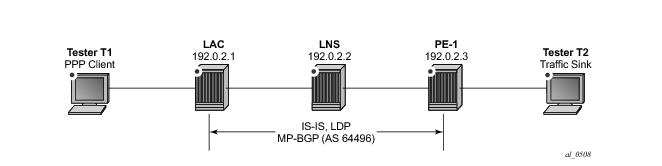
The interface loopback represents a logical loopback interface which is used as the LNS endpoint address in L2TP signaling. The LAC has a corresponding interface with IP address 192.168.0.1. It also represents the unnumbered interface address referenced in the
subscriber-interface context, meaning this IP address is used for the purpose of IPCP negotiation with incoming PPP sessions. Within the
subscriber-interface context, the
group-interface has a different definition than a conventional ESM
group-interface. A conventional
group-interface has one or more SAPs belonging to the same port or LAG. However, in the context of LNS, there are no SAPs. The group-interface also might terminate sessions within the same L2TP tunnel which are anchored on different MS-ISAs in a common lns-group. To accommodate this, the
group-interface has the
creation-time attribute
lns. This attribute essentially means that the group-interface can terminate subscribers from more than one port/LAG; where port/LAG is interpreted as different MS-ISAs.
The group-interface then provides a
sap-parameters context that allows for configuration of
sub-sla-mgmt parameters that would typically be found under a SAP. These parameters are applicable to all subscribers terminated on this group-interface. In the example shown, only the
sub-ident-policy is configured; hence there is an expectation that other ESM parameters such as
sla-profile,
sub-profile, and
subscriber-id, will be learned from a different source (in this example, they will be learned from RADIUS).
Within the l2tp context, there exists a hierarchy of groups and tunnels. Groups reside directly under the
l2tp context, and tunnels reside within the group context. Groups are intended to administratively organize tunnels that may share a common use or contain common parameters. The L2TP tunnel characteristics can be inherited from the group context, or overridden within the
tunnel context. In the group context shown in the output below, the
lns-group 1 command refers to the
lns-group previously configured at the ISA level. This is followed by the
local-address command that indicates an IP address to be used as a source address for L2TP signaling. The ppp context then defines the characteristics of how the PPP session will be established. In this case, the authentication mechanism is CHAP, and the previously configured RADIUS
authentication-policy is used to authenticate the user. During the PPP session set-up, the LAC negotiates LCP and authentication parameters with the subscriber. Two AVPs, the
Proxy LCP AVP and the
Proxy Authentication AVP allow this information to be forwarded by the LAC to the LNS. This information can be accepted by the LNS, allowing PPP to continue with negotiation of IPCP, or it can be rejected, in which case the LNS initiates a new round of NCP and PPP authentication.The
proxy-authentication and
proxy-lcp commands allow the information contained in these AVPs to be accepted.
Finally, the tunnel context provides the context for explicit configuration related to this L2TP tunnel. The
peer command indicates the far-end (LAC) IP address to which L2TP messages are addressed. The
password is used to authenticate the far-end tunnel initiator, and is used in conjunction with the
challenge parameter to implement a CHAP-like authentication mechanism. The default behavior is to never challenge the initiator (LAC); hence the
challenge always setting is the inverse of this behavior. The
remote-name is used to provide an additional level of security. When the Start Control Connection Request (SCCRQ) is received from the LAC to initiate the tunnel set-up it carries a mandatory
Host Name AVP. The value of this AVP is compared to the name configured in the
remote-name, and only tunnels with matching names are accepted. In a similar manner, the
local-name parameter is used to populate the Host Name AVP sent by the LNS in the SCCRP, and can be used as a similar security feature at the LAC.
service
vprn 1 customer 1 create
vrf-import vrf1-import
vrf-export vrf1-export
route-distinguisher 64496:1
auto-bind ldp
interface "loopback" create
address 192.168.0.2/32
loopback
exit
subscriber-interface "LNS-SUB-INT" create
unnumbered 192.168.0.2
group-interface "LNS-GROUP-INT" lns create
sap-parameters
sub-sla-mgmt
sub-ident-policy "all-subscribers"
exit
exit
exit
exit
static-route 10.48.127.0/24 black-hole
l2tp
group "L2TP-GROUP-1" create
lns-group 1
local-address 192.168.0.2
ppp
authentication chap
authentication-policy "AAA-AUTH-POLICY"
keepalive 10 hold-up-multiplier 3
proxy-authentication
proxy-lcp
exit
tunnel "L2TP-TUNNEL-1" create
challenge always
local-name "LNS"
peer 192.168.0.1
remote-name "LAC"
password <password> hash2
no shutdown
exit
no shutdown
exit
no shutdown
exit
no shutdown
exit
As previously described, RADIUS is used to authenticate the subscriber, which upon successful authentication returns the ESM parameters, Subscriber-ID (Alc-Subsc-ID-Str), SLA-Profile (
Alc-SLA-Prof-Str), and Sub-Profile (
Alc-Subsc-Prof-Str) as needed for instantiating the subscriber in SR OS. These parameters could be obtained locally on the LNS using the
def-sub-id,
def-sla-profile and
def-sub-profile commands under the
group-interface sap-parameters. This enables a mechanism to provide default parameters in the absence of obtaining them from another source. However, passing them from RADIUS has some benefits, such as:
subscriber1@isp.net Cleartext-Password := "password"
Alc-Subsc-ID-Str = "subscriber1@isp.net",
Alc-Subsc-Prof-Str = "ESM-SUB-PROF",
Alc-SLA-Prof-Str = "ESM-SLA-PROF",
Alc-Serv-Id = "1",
Alc-Interface = "LNS-GROUP-INT",
Service-Type = Framed-User,
Framed-Protocol = PPP,
Framed-IP-Address = 10.48.127.27,
The SCCRQ is used to initialize the tunnel between LAC and LNS, and although it can be sent by either the LAC or LNS, it is typically sent by the LAC towards the LNS (as in this example). The SCCRQ contains a number of mandatory AVPs, denoted by the M-bit in the AVP header (set to 1), including Message Type, Protocol Version, Host Name, Framing Capabilities, and Assigned Tunnel ID. It can also contain a number of optional AVPs, such as Vendor Name, and Firmware Revision, which can be ignored by the recipient if they are unrecognized.
7 2014/02/14 16:16:01.03 GMT MINOR: DEBUG #2001 vprn1 L2TP(v2, ctrl, ingress)
"L2TP(v2, ctrl, ingress): UDP 192.168.0.1:1701 -> 192.168.0.2:1701
tunnel 0 session 0, ns 0 nr 0, flags:, reserved=0
AVP MessageType(0,0), flags: mandatory, reserved=0
StartControlConnectionRequest(1)
AVP ProtocolVersion(0,2), flags: mandatory, reserved=0
version=1, revision=0
AVP HostName(0,7), flags: mandatory, reserved=0
"LAC"
AVP WindowSize(0,10), flags: mandatory, reserved=0
64
AVP FramingCapabilities(0,3), flags: mandatory, reserved=0
sync=no, async=no
AVP BearerCapabilities(0,4), flags: mandatory, reserved=0
digital=yes, analogue=no
AVP FirmwareRevision(0,6), flags:, reserved=0
2816
AVP VendorName(0,8), flags:, reserved=0
"Alcatel-Lucent"
AVP AssignedTunnelId(0,9), flags: mandatory, reserved=0
12763"
8 2014/02/14 16:16:01.03 GMT MINOR: DEBUG #2001 vprn1 L2TP(v2, ctrl, egress)
"L2TP(v2, ctrl, egress): UDP 192.168.0.2:1701 -> 192.168.0.1:1701
tunnel 12763 session 0, ns 0 nr 1, flags:, reserved=0
AVP MessageType(0,0), flags: mandatory, reserved=0
StartControlConnectionReply(2)
AVP ProtocolVersion(0,2), flags: mandatory, reserved=0
version=1, revision=0
AVP HostName(0,7), flags: mandatory, reserved=0
"LNS"
AVP WindowSize(0,10), flags: mandatory, reserved=0
64
AVP FramingCapabilities(0,3), flags: mandatory, reserved=0
sync=no, async=no
AVP BearerCapabilities(0,4), flags: mandatory, reserved=0
digital=yes, analogue=no
AVP FirmwareRevision(0,6), flags:, reserved=0
2816
AVP VendorName(0,8), flags:, reserved=0
"Alcatel-Lucent"
AVP AssignedTunnelId(0,9), flags: mandatory, reserved=0
10439
AVP Challenge(0,11), flags: mandatory, reserved=0
b1 97 6c f2 b2 ec a9 7c 48 ec c9 7f f0 66 a5 b4
a8 33 bb 4d cb 2f db 50 c3 28 73 e3 61 99 f6 45
48 d0 90 ae 29 52 a9 c7 3b 11 65 f6 bd 62 a4 33 "
9 2014/02/14 16:16:01.03 GMT MINOR: DEBUG #2001 vprn1 L2TP(v2, ctrl, ingress)
"L2TP(v2, ctrl, ingress): UDP 192.168.0.1:1701 -> 192.168.0.2:1701
tunnel 10439 session 0, ns 1 nr 1, flags:, reserved=0
AVP MessageType(0,0), flags: mandatory, reserved=0
StartControlConnectionConnected(3)
AVP ChallengeResponse(0,13), flags: mandatory, reserved=0
0c fb ce d3 e6 38 2a 41 d7 9a 8e a4 fa a7 df ff "
*A:LNS# show router 1 l2tp tunnel
===============================================================================
Conn ID Loc-Tu-ID Rem-Tu-ID State Blacklist-state Ses Active
Group Ses Total
Assignment
-------------------------------------------------------------------------------
684130304 10439 12763 establishedIdle not-blacklisted 0
L2TP-GROUP-1 0
L2TP-TUNNEL-1
-------------------------------------------------------------------------------
No. of tunnels: 1
===============================================================================
Once a tunnel is established, maintenance and health-checking of that tunnel is achieved using a keepalive mechanism that employs Hello control messages. The Hello message contains only one AVP, the Message Type AVP, which indicates it is a Hello message. The Hello messages operate asynchronously between the peers. There is no echo request and echo response function, but simply a Hello followed by an acknowledgment. The Hello is acknowledged in the same way as other control messages, using either piggy-backing or ZLB acknowledgments. This asynchronous behavior allows for either end of the tunnel to be configured for different Hello intervals (they are not negotiated), or even for one end not send Hellos at all.
89 2014/02/18 17:40:47.16 GMT MINOR: DEBUG #2001 vprn1 L2TP(v2, ctrl, egress)
"L2TP(v2, ctrl, egress): UDP 192.168.0.2:1701 -> 192.168.0.1:1701
tunnel 10131 session 0, ns 1 nr 2, flags:, reserved=0
AVP MessageType(0,0), flags: mandatory, reserved=0
Hello(6)"
90 2014/02/18 17:40:47.17 GMT MINOR: DEBUG #2001 vprn1 L2TP(v2, ctrl, ingress)
"L2TP(v2, ctrl, ingress): UDP 192.168.0.1:1701 -> 192.168.0.2:1701
tunnel 8744 session 0, ns 2 nr 2, flags:, reserved=0"
The Hello interval at the LNS is configurable under the l2tp, group, or tunnel contexts using the hello-interval parameter. The range is 60 to 3600 seconds, with the default being 300 seconds. The
hello-interval infinite option suppresses sending of Hellos. If the system sends a Hello message and does not get an acknowledgment, it will re-transmit the Hello message as many times as the value of the
max-retries-estab parameter, each time with an exponential
1 back-off. The
max-retries-estab parameter can be configured in the l2tp, group, or tunnel contexts. The default value is 5, and if no acknowledgment is received before this value is exceeded, the tunnel is declared down and a StopCCN is sent towards the peer.
15 2014/02/18 16:54:58.89 GMT MINOR: DEBUG #2001 vprn1 L2TP(v2, ctrl, ingress)
"L2TP(v2, ctrl, ingress): UDP 192.168.0.1:1701 -> 192.168.0.2:1701
tunnel 12234 session 0, ns 2 nr 1, flags:, reserved=0
AVP MessageType(0,0), flags: mandatory, reserved=0
StopControlConnectionNotification(4)
AVP ResultCode(0,1), flags: mandatory, reserved=0
result-code: "generalRequestToClearControlConnection"(1), error-code: "n
oGeneralError"(0)
error-msg: "operator request"
AVP AssignedTunnelId(0,9), flags: mandatory, reserved=0
5826"
The tunnel Connection Id can be used as an additional argument to display the details of a particular tunnel when multiple tunnels are present. The following output is an example of this taken just after the L2TP tunnel has been closed by the LAC peer, and is intentionally taken at this time to illustrate the purpose of some of the fields shown in the output. The State is moved to
closedByPeer, and the Stop CCN Result field and Error Message field respectively contain the result code and error code of the Result Code AVP received from the LAC in the StopCCN. Because the tunnel is now in a closedByPeer state, all state and information related to this tunnel is removed from the system after a period defined by the Destruct Timeout (shown in the output as Destruct TO). The intention of the Destruct Timeout is to retain information about the tunnel closure which might aid operational communities. The default value as shown is 60 seconds, but it can be configured using the
destruct-timeout parameter in the l2tp, group, or tunnel contexts. The remainder of the fields in the output are the operational parameters of the tunnel and are self-explanatory.
*A:LNS# show router 1 l2tp tunnel connection-id 684130304 detail
===============================================================================
L2TP Tunnel Status
===============================================================================
Connection ID: 684130304
State : closedByPeer
IP : 192.168.0.2
UDP : 1701
Peer IP : 192.168.0.1
Peer UDP : 1701
Tx dst-IP : 192.168.0.1
Tx dst-UDP : 1701
Rx src-IP : 192.168.0.1
Rx src-UDP : 1701
Name : LNS
Remote Name : LAC
Assignment ID: L2TP-TUNNEL-1
Group Name : L2TP-GROUP-1
Acct. Policy : N/A
Error Message: operator request
Remote Conn ID : 836435968
Tunnel ID : 10439 Remote Tunnel ID : 12763
Preference : 50 Receive Window : 64
Hello Interval (s): 300
Idle TO (s) : infinite Destruct TO (s) : 60
Max Retr Estab : 5 Max Retr Not Estab: 5
Session Limit : 32767 AVP Hiding : never
Transport Type : udpIp Challenge : always
Time Started : 02/14/2014 16:16:01 Time Idle : N/A
Time Established : 02/14/2014 16:16:01 Time Closed : 02/14/2014 16:35:51
Stop CCN Result : generalReq General Error : noError
Blacklist-state : not-blacklisted
-------------------------------------------------------------------------------
===============================================================================
70 2014/02/19 11:05:35.74 GMT MINOR: DEBUG #2001 vprn1 L2TP(v2, ctrl, ingress)
"L2TP(v2, ctrl, ingress): UDP 192.168.0.1:1701 -> 192.168.0.2:1701
tunnel 8010 session 0, ns 5 nr 23, flags:, reserved=0
AVP MessageType(0,0), flags: mandatory, reserved=0
IncomingCallRequest(10)
AVP AssignedSessionId(0,14), flags: mandatory, reserved=0
7886
AVP CallSerialNumber(0,15), flags: mandatory, reserved=0
18
AVP CallingNumber(0,22), flags: mandatory, reserved=0
"BBEU4966723450"
AVP AgentCircuitId(3561,1), flags:, reserved=0
"dslam142-atm4/2/7:0.101"
AVP AgentRemoteId(3561,2), flags:, reserved=0
"BBEU4966723450"
AVP ActDataRateUp(3561,129), flags:, reserved=0
2048000
AVP ActDataRateDown(3561,130), flags:, reserved=0
8192000"
72 2014/02/19 11:05:35.75 GMT MINOR: DEBUG #2001 vprn1 L2TP(v2, ctrl, egress)
"L2TP(v2, ctrl, egress): UDP 192.168.0.2:1701 -> 192.168.0.1:1701
tunnel 173 session 7886, ns 23 nr 6, flags:, reserved=0
AVP MessageType(0,0), flags: mandatory, reserved=0
IncomingCallReply(11)
AVP AssignedSessionId(0,14), flags: mandatory, reserved=0
26097"
The final message in the three-way exchange used for establishing sessions within the tunnel is the ICCN. It is sent by the LAC to the LNS to indicate that the call has been answered, so the L2TP session is moved to the established state. It also provides additional information on parameters that were used to answer the call which may not have been available when the ICRQ was sent (although it is likely that in most cases they were available). At a minimum, the ICCN must contain the Message Type, Framing Type and TX Connect Speed AVPs. The TX Connect Speed defines the speed in bits-per-second from the perspective of traffic flowing from the LAC towards the subscriber (i.e. the LAC downstream rate) and, for best accuracy, can be derived by the LAC from the PPP Broadband Forum Access Line Characteristic tags inserted by the access node (Appendix C TR-101). The TX Connect Speed can be useful for indirect setting of a Hierarchical QoS (H-QoS) aggregate rate. It is indirect because the LNS cannot infer and set an aggregate rate based directly on the TX Connect Speed AVP, but rather the TX Connect Speed is passed to RADIUS (using the
include-radius-attribute access-loop-option parameter in the authentication-policy), which in turn may pass the aggregate rate to the LNS in a QoS override VSA. This is discussed further in the QoS section.
74 2014/02/19 11:05:35.76 GMT MINOR: DEBUG #2001 vprn1 L2TP(v2, ctrl, ingress)
"L2TP(v2, ctrl, ingress): UDP 192.168.0.1:1701 -> 192.168.0.2:1701
tunnel 8010 session 26097, ns 6 nr 24, flags:, reserved=0
AVP MessageType(0,0), flags: mandatory, reserved=0
IncomingCallConnected(12)
AVP FramingType(0,19), flags: mandatory, reserved=0
sync=no, async=no
AVP TxConnectSpeed(0,24), flags: mandatory, reserved=0
8192000
AVP InitialRxLcpConfReq(0,26), flags:, reserved=0
05 06 0f 09 4b f8 01 04 ff fb
[5] Magic-Number: 0x0f094bf8
[1] MRU: 65531
AVP LastTxLcpConfReq(0,27), flags:, reserved=0
01 04 05 d4 03 05 c2 23 05 05 06 7f 59 e9 8a
[1] MRU: 1492
[3] Authentication-Protocol: 0xc223 (CHAP), Algorithm = 5 (MD5)
[5] Magic-Number: 0x7f59e98a
AVP LastRxLcpConfReq(0,28), flags:, reserved=0
05 06 0f 09 4b f8 01 04 ff fb
[5] Magic-Number: 0x0f094bf8
[1] MRU: 65531
AVP ProxyAuthenType(0,29), flags:, reserved=0
chap(2)
AVP ProxyAuthenName(0,30), flags:, reserved=0
"subscriber1@isp.net"
AVP ProxyAuthenChallenge(0,31), flags:, reserved=0
a9 42 72 2b 62 2a 71 a2 71 ce 20 06 bf a7 6d e8
4f 3a 45 c3 46 10 93 4f 1c 46 46 79 a4 05 11 4e
47 03 f9
AVP ProxyAuthenId(0,32), flags:, reserved=0
id=1, reserved=0
AVP ProxyAuthenResponse(0,33), flags:, reserved=0
fa a3 27 06 1d fe f4 9f 8c 72 a9 ac b8 5e 1b a8
AVP RxConnectSpeed(0,38), flags:, reserved=0
2048000"
*A:LNS# show router 1 l2tp session
===============================================================================
L2TP Session Summary
===============================================================================
ID Control Conn ID Tunnel-ID Session-ID State
------------------------------------------------------------------------
524969457 524943360 8010 26097 established
subscriber1@isp.net
interface: LNS-GROUP-INT
service-id: 1
10.48.127.27
-------------------------------------------------------------------------------
No. of sessions: 1
===============================================================================
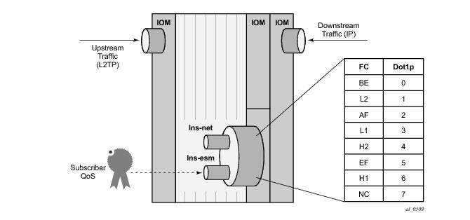
The PPP session is also in the subscriber-host table of VPRN 1 and a forwarding state of Fwding indicates that all attributes and resources associated with this subscriber are correctly installed and activated within the system. The subscriber username is shown, as is it’s MAC address and IP address. The IP address has an origin of IPCP. The fact that a MAC address is displayed here is somewhat misleading because this is a PPP over L2TP session, which does not have a MAC address present in any of it’s headers. When the MS-ISA removes the L2TP header it converts the PPP packet to PPPoE for ease of subsequent processing. As a result of this, the MS-ISA generates a fake MAC address, and this is the MAC address shown. The displayed SAP 5/1/lns-esm:1.486 is automatically generated by the system. Each operational MS-ISA that is part of the lns-group creates two internal objects, known as lns-net and lns-esm. These objects essentially represent a network-side (lns-net) and subscriber-side (lns-esm) of each MS-ISA.
When the first L2TP session within this service is established the system creates one lns-esm SAP where the first two digits indicate the MDA slot (5/1) where the MS-ISA is installed, and the last two numbers are the internal Q-in-Q tags used through the MS-ISA (1.486)
2. If there are more than one MS-ISA active in the lns-group, a second session would be load-balanced onto this MS-ISA, and a second lns-esm SAP would be created, until a maximum of six SAPs is reached, which represents the maximum number of supported active MS-ISA boards.
*A:LNS# show service id 1 subscriber-hosts
=============================================================
Subscriber Host table
=============================================================
Sap Subscriber
IP Address
MAC Address PPPoE-SID Origin Fwding State
-------------------------------------------------------------
[5/1/lns-esm:1.486] subscriber1@isp.net
10.48.127.27
00:00:1f:4a:65:f1 1 IPCP Fwding
-------------------------------------------------------------
Number of subscriber hosts : 1
=============================================================
It is also possible to view the internal lns-net object, shown in the next output as interface name _tmnx_lns-in-5/1 with port number
5/1/lns-net:1*. To further clarify (and reiterate), the lns-esm and lns-net are simply internal objects used to route L2TP traffic through the MS-ISA board. Upstream traffic (subscriber to LNS) ingresses through lns-net into the MS-ISA where the L2TP header is decapsulated before PPP packets are presented to the service group-interface through lns-esm. Downstream traffic (LNS to subscriber) passes through lns-esm into the MS-ISA where the PPP packets are encapsulated in L2TP before egressing through lns-net and being routed towards the destination.
*A:LNS# show service id 1 interface
===============================================================================
Interface Table
===============================================================================
Interface-Name Adm Opr(v4/v6) Type Port/SapId
IP-Address PfxState
-------------------------------------------------------------------------------
loopback Up Up/Down VPRN loopback
192.168.0.2/32 n/a
LNS-SUB-INT Up Up/Down VPRN S* subscriber
Unnumbered If[192.168.0.2] n/a
LNS-GROUP-INT Up Up/Down VPRN G* bbg-5.lns-esm
_tmnx_lns-in-5/1 Up Up/Down VPRN 5/1/lns-net:1*
- -
-------------------------------------------------------------------------------
Interfaces : 4
===============================================================================
To achieve this, a second service is created which becomes the ‘Retail VRF’, or customer-specific VRF, and the previously defined VPRN 1 becomes the Wholesale VRF (which actually requires no further configuration). The necessary configuration for the Retail VRF is shown below and it’s parameters have been previously explained. Although they may seem obvious, there are a couple of points that are worth revisting. The vrf-import and
vrf-export parameters are used to reference policies to import/export VPN-IPv4/v6 prefixes with the customer-specific Route-Target Extended Communities. Given that a different routing context and unique Route-Targets are used for this Retail VRF, it is perfectly feasible to re-use the same IP address in VPRN 2 as was used in VPRN 1 for the unnumbered subscriber-interface. The group-interface has a different name from the group-interface in VPRN 1, but this is simply for illustration purposes and both group-interfaces can have the same name if a standard naming convention is required. More importantly, the group-interface must have the creation-time attribute
lns to allow subscriber termination without SAPs. The static route blackholes prefix 10.10.148.0/24, ensuring this prefix is added to the route-table. This IP address range is used to allocate addresses to subscribers, and is therefore advertised in VPN-IPv4.
service
vprn 2 customer 1 create
vrf-import "vrf2-import"
vrf-export "vrf2-export"
route-distinguisher 64496:2
auto-bind ldp
interface "loopback" create
address 192.168.0.2/32
loopback
exit
subscriber-interface "VPRN2-SUB-INT" create
unnumbered 192.168.0.2
group-interface "VPRN2-GROUP-INT" lns create
sap-parameters
sub-sla-mgmt
sub-ident-policy "all-subscribers"
exit
exit
exit
exit
static-route 10.10.148.0/24 black-hole
no shutdown
exit
In addition to the Retail VRF configuration, the RADIUS entry for the subscriber returns Alc-Serv-Id VSA with a value of 2 to indicate the Retail VRF Service Id, while the
Alc-Interface VSA refers to the group-interface name within that Retail VRF.
subscriber2@isp.net Cleartext-Password := "password"
Alc-Subsc-ID-Str = "subscriber2@isp.net",
Alc-Subsc-Prof-Str = "ESM-SUB-PROF",
Alc-SLA-Prof-Str = "ESM-SLA-PROF",
Alc-Serv-Id = "2",
Alc-Interface = "VPRN2-GROUP-INT",
Service-Type = Framed-User,
Framed-Protocol = PPP,
Framed-IP-Address = 10.10.148.22
Once the subscriber is activated, the PPP session and subscriber-host can be seen in VPRN 2. The description field of the show service id 2 ppp session command is however somewhat misleading. It is automatically concatenated from the VPRN that terminated the L2TP tunnel, the tunnel Connection Id, the local tunnel Id, and the L2TP session Id. It should not be misinterpreted as meaning that the subscriber has been terminated in VPRN 1.
*A:LNS# show service id 2 ppp session
===============================================================================
PPP sessions for service 2
===============================================================================
User-Name
Descr.
Up Time Type Termination IP/L2TP-Id/Interface-Id MC-Stdby
-------------------------------------------------------------------------------
subscriber2@isp.net
vprn:1 connid:524964710 tid:8010 sid:21350
0d 00:00:10 oL2tp local 10.10.148.22
-------------------------------------------------------------------------------
No. of PPP sessions: 1
===============================================================================
qos
sap-ingress 10 create
queue 1 create
exit
queue 11 multipoint create
exit
fc "af" create
queue 1
exit
fc "be" create
queue 1
exit
fc "ef" create
queue 1
exit
dscp be fc "be"
dscp ef fc "ef"
dscp af31 fc "af"
exit
qos
scheduler-policy "Subscriber-Aggregate-Policy" create
tier 1
scheduler "Aggregrate-Rate" create
rate 8000
exit
exit
exit
qos
sap-egress 10 create
queue 1 create
parent "Aggregrate-Rate" level 2 weight 20
exit
queue 2 best-effort create
parent "Aggregrate-Rate" level 2 weight 80
exit
queue 3 expedite create
parent "Aggregrate-Rate" cir-level 3
rate 1024 cir 1024
exit
fc af create
queue 2
exit
fc be create
queue 1
exit
fc ef create
queue 3
exit
dscp be fc "be"
dscp ef fc "ef"
dscp af31 fc "af"
exit
subscriber-mgmt
sla-profile "ESM-SLA-PROF" create
ingress
qos 10
exit
exit
egress
qos 10
exit
no qos-marking-from-sap
exit
exit
sub-profile "ESM-SUB-PROF" create
collect-stats
radius-accounting-policy "AAA-ACCT-POLICY"
egress
scheduler-policy "Subscriber-Aggregate-Policy"
exit
exit
exit
The queues assigned to the subscriber through the above SAP-ingress/egress QoS policies, together with accumulative statistics can be viewed using the show service active-subscribers subscriber <
name>
detail command (real time rates can be seen using the
monitor command). The H-QoS scheduler hierarchy, with the SAP-egress queues mapped as child queues to a parent scheduler can be validated using the command
show qos scheduler-hierarchy subscriber <
name>
egress. The
detail argument as an extension of this command provides a significant amount of detail on real-time bandwidth allocated to each queue by the scheduler in the within-CIR and above-CIR passes. It also provides a useful snapshot on offered traffic loads in Kb/s on a per-queue basis.
*A:LNS# show qos scheduler-hierarchy subscriber "subscriber2@isp.net" egress
===============================================================================
Scheduler Hierarchy - Subscriber subscriber2@isp.net
===============================================================================
Egress Scheduler Policy : Subscriber-Aggregate-Policy
-------------------------------------------------------------------------------
Root (Egr)
| slot(5)
|--(S) : Aggregrate-Rate
| |
| |--(Q) : Sub=subscriber2@isp.net:ESM-SLA-PROF 2->5/1/lns-esm:1.481->3
| |
| |--(Q) : Sub=subscriber2@isp.net:ESM-SLA-PROF 2->5/1/lns-esm:1.481->2
| |
| |--(Q) : Sub=subscriber2@isp.net:ESM-SLA-PROF 2->5/1/lns-esm:1.481->1
| |
===============================================================================
qos
port-scheduler-policy "egress-port-scheduler" create
exit
port-policy "isa-port-policy" create
egress-scheduler-policy "egress-port-scheduler"
exit
isa
lns-group 1 create
mda 5/1
port-policy "isa-port-policy"
no shutdown
exit
Once the port-scheduler policy and
port-policy are in place, the subscriber QoS can reference it. The QoS configuration previously used for conventional H-QoS schedulers differs in both the
sap-egress policy and
sub-profile when an egress
port-scheduler is used. The queues within the
sap-egress policy are each configured to be parented to the egress port-scheduler using the
port-parent keyword (as opposed the
parent keyword used for conventional H-QoS schedulers).
qos
sap-egress 10 create
queue 1 create
port-parent level 2 weight 20
exit
queue 2 best-effort create
port-parent level 2 weight 80
exit
queue 3 expedite create
port-parent cir-level 3
rate 1024 cir 1024
exit
fc af create
queue 2
exit
fc be create
queue 1
exit
fc ef create
queue 3
exit
dscp be fc "be"
dscp ef fc "ef"
dscp af31 fc "af"
exit
subscriber-mgmt
sub-profile "ESM-SUB-PROF" create
radius-accounting-policy "AAA-ACCT-POLICY"
egress
agg-rate-limit 8000
exit
exit
Once again, the queues assigned to the subscriber through the above SAP-ingress/egress QoS policies, together with accumulative statistics can be viewed using the show service active-subscribers subscriber <name> detail command (real time rates can be seen using the
monitor command). The scheduler SAP-egress queues mapped as child queues to a port-scheduler can be validated using the
show qos scheduler-hierarchy subscriber <name> egress command. The
detail argument as an extension of this command provides a significant amount of detail on bandwidth allocated to each queue by the scheduler in the within-CIR and above-CIR passes. It also provides a useful snapshot on offered traffic loads in Kb/s on a per-queue basis. Alternatively, all of the child queues and orphans mapped to the port-scheduler can be displayed using the
show qos scheduler-hierarchy port <slot/mda/lns-esm> command, again with the optional
detail argument.
*A:LNS# show qos scheduler-hierarchy subscriber "subscriber2@isp.net" egress
===============================================================================
Scheduler Hierarchy - Subscriber subscriber2@isp.net
===============================================================================
Egress Scheduler Policy :
-------------------------------------------------------------------------------
Root (Egr)
| slot(5)
|--(Q) : Sub=subscriber2@isp.net:ESM-SLA-PROF 2->5/1/lns-esm:1.481->3 (Port 5/1/lns-esm)
|
|--(Q) : Sub=subscriber2@isp.net:ESM-SLA-PROF 2->5/1/lns-esm:1.481->2 (Port 5/1/lns-esm)
|
|--(Q) : Sub=subscriber2@isp.net:ESM-SLA-PROF 2->5/1/lns-esm:1.481->1 (Port 5/1/lns-esm)
|
===============================================================================
With the previously configured QoS policies and schedulers in place, the aggregate rate limit in use for the subscriber can be viewed using the show service active-subscribers subscriber <
name>
detail command. There are three fields in this output that are of interest here. The
E. Agg Rate Limit field shows the configured rate-limit in the sub-profile and is therefore relatively static. The
RADIUS Rate-Limit field shows the aggregate rate received by RADIUS using the
Alc-Subscriber-QoS-Override VSA, which overrides any rate-limit statically configured in the sub-profile. Finally, the Oper-Rate-Limit shows the static or RADIUS-received rate-limit, minus any other H-QoS adjustments, such as Multicast H-QoS adjustment (snooping on IGMP joins) or ANCP line-rate adjustments.
*A:LNS# show service active-subscribers subscriber "subscriber2@isp.net" detail | match expression "E. Agg Rate Limit|RADIUS Rate-Limit|Oper-Rate-Limit"
E. Sched. Policy : N/A E. Agg Rate Limit: 8000
RADIUS Rate-Limit: N/A
Oper-Rate-Limit : 8000
Overriding the agg-rate-limit defined in the sub-profile can be done as part of the RADIUS Access-Accept, or through a Change of Authorization (CoA), and as previously outlined uses the
Alc-Subscriber-QoS-Override VSA. This override function can be used, for example, to reconcile the LNS aggregate rate with the subscriber downstream rate learned through the TxConnectSpeed AVP in the ICCN message from the LAC. This ensures that the LNS does not overwhelm any downstream access node, and ensures that the LNS is responsible for all QoS scheduling in the event of congestion. In the following example, an override of the aggregate rate to 10Mb/s is sent as a CoA.
7 2014/02/21 16:37:23.94 GMT MINOR: DEBUG #2001 management RADIUS
"RADIUS: Receive
Change of Authorization(43) id 117 len 66 from 172.20.148.7:37006 vrid 4095
SESSION ID [44] 22 C482020000018C53077F48
VSA [26] 16 Alcatel(6527)
SUBSCRIBER QOS OVERRIDE [126] 14 e:r:rate=10000
"
Re-issuing the show service active-subscribers subscriber <
name>
detail command after the CoA shows that the
RADIUS Rate-Limit field and the
Oper-Rate-Limit field both correctly show 10Mb/s.
*A:LNS# show service active-subscribers subscriber "subscriber2@isp.net" detail | match expression "E. Agg Rate Limit|RADIUS Rate-Limit|Oper-Rate-Limit"
E. Sched. Policy : N/A E. Agg Rate Limit: 8000
RADIUS Rate-Limit: 10000
Oper-Rate-Limit : 10000
qos
sap-egress 10 create
queue 1 create
exit
queue 2 best-effort create
exit
queue 3 expedite create
exit
fc af create
queue 2
dot1p 2
exit
fc be create
queue 1
dot1p 0
exit
fc ef create
queue 3
dot1p 5
exit
dscp be fc "be"
dscp ef fc "ef"
dscp af31 fc "af"
exit
To provide an example of the use of Framed-Route, the Retail VRF VPRN 2 is again used, and in fact requires no modification in order to support subscribers with Framed-Routes. In general ESM, where Framed-Route is used, there is a requirement to configure anti-spoof type nh-mac, but for LNS SAPs this is the default. The RADIUS users file is updated to return a Framed-Route attribute for prefix 10.128.46.0/24 with a next-hop determined by the subscriber IP prefix. The prefix has a metric of 10, and has a tag of value 200, which may be used for example, for routing policy.
subscriber2@isp.net Cleartext-Password := "password1"
Alc-Subsc-ID-Str = "subscriber2@isp.net",
Alc-Subsc-Prof-Str = "ESM-SUB-PROF",
Alc-SLA-Prof-Str = "ESM-SLA-PROF",
Alc-Serv-Id = "2",
Alc-Interface = "VPRN2-GROUP-INT",
Service-Type = Framed-User,
Framed-Protocol = PPP,
Framed-IP-Address = 10.10.148.22,
Framed-Route = "10.128.46.0/24 0.0.0.0 10 tag 200",
In SR OS, a prefix learned through the Framed-Route attribute is known internally as a Managed Route. Once the subscriber is instantiated, the presence of the Managed Route can be verified as installed.
*A:LNS# show service id 2 ppp session detail | match "Managed Routes" post-lines 5
Managed Routes
-------------------------------------------------------------------------------
IP Address Status Metric Tag Pref
-------------------------------------------------------------------------------
10.128.46.0/24 installed 10 200 0
-------------------------------------------------------------------------------
*A:LNS# show router 2 route-table protocol managed
===============================================================================
Route Table (Service: 2)
===============================================================================
Dest Prefix[Flags] Type Proto Age Pref
Next Hop[Interface Name] Metric
-------------------------------------------------------------------------------
10.128.46.0/24 Remote Managed 01h41m18s 0
10.10.148.22 10
-------------------------------------------------------------------------------
No. of Routes: 1
Flags: L = LFA nexthop available B = BGP backup route available
n = Number of times nexthop is repeated
===============================================================================
The RADIUS users file for subscriber1@isp.net is modified to include a number of additional attributes and VSAs. As previously described, the Alc-Serv-Id and
Alc-Interface define the service ID and group-interface where the subscriber is terminated, and this can be any IES or VPRN service. The
Alc-Tunnel-Serv-Id VSA is used to identify the service from which the L2TP tunnel is initiated. This can be the same service in which the subscriber is terminated, or it can be a different service. If it is a different service, then the minimum requirement is that L2TP is placed in a no shutdown state. In this example, the subscriber is terminated in service VPRN 1 and the L2TP tunnel is also initiated from service VPRN 1. The remaining attributes are standard attributes defined in RFC 2868 for L2TP tunnel set-up. Note that the Tunnel-Assignment-Id attribute is used to maintain the concept of groups and tunnels, where Tunnel-Assignment-Id:0 is used to indicate the group name and Tunnel-Assignment-Id:1 is used to indicate the tunnel name. This provides sufficient information for the LTS to be able to initiate an L2TP tunnel without any requirement for nodal configuration above that already configured.
subscriber1@isp.net Cleartext-Password := "password1"
Alc-Subsc-ID-Str = "subscriber1@isp.net",
Alc-Subsc-Prof-Str = "ESM-SLA-PROF",
Alc-SLA-Prof-Str = "ESM-SUB-PROF",
Alc-Serv-Id = "1",
Alc-Interface = "LNS-GROUP-INT",
Alc-Tunnel-Serv-Id = 1,
Tunnel-Assignment-Id:0 = "RADIUS-returned-Tunnel-Group",
Tunnel-Type:1 += L2TP,
Tunnel-Medium-Type:1 += IP,
Tunnel-Server-Endpoint:1 += 192.168.0.3,
Tunnel-Password:1 += "password",
Tunnel-Assignment-Id:1 += "RADIUS-returned-Tunnel-Name",
Tunnel-Client-Auth-Id = "LTS",
*A:LNS# show service id 1 ppp session
===============================================================================
PPP sessions for service 1
===============================================================================
User-Name
Descr.
Up Time Type Termination IP/L2TP-Id/Interface-Id MC-Stdby
-------------------------------------------------------------------------------
subscriber1@isp.net
vprn:1 connid:864561329 tid:13192 sid:10417
0d 16:21:58 oL2tp lac 557659129
-------------------------------------------------------------------------------
No. of PPP sessions: 1
===============================================================================
Within VPRN 1 there are two L2TP tunnels active. The first entry with Connection Id 557645824 belongs to group RADIUS-returned-Tunnel-Group (derived from RADIUS attribute Tunnel-Assignment-Id:0) and has tunnel name
RADIUS-returned-Tunnel-Name (derived from RADIUS attribute Tunnel-Assignment-Id:1). This is the tunnel from LTS to LNS, and it is in the
Established state and has one session active. The second entry with Connection Id 864550912 is the statically defined tunnel from the LAC, belonging to the CLI-configured group L2TP-GROUP-1 with tunnel name L2TP-TUNNEL-1. This tunnel is also in the
Established state, with one session active.
*A:LNS# show router 1 l2tp tunnel
===============================================================================
Conn ID Loc-Tu-ID Rem-Tu-ID State Blacklist-state Ses Active
Group Ses Total
Assignment
-------------------------------------------------------------------------------
557645824 8509 9488 established not-blacklisted 1
RADIUS-returned-Tunnel-Group 1
RADIUS-returned-Tunnel-Name
864550912 13192 7204 established not-blacklisted 1
L2TP-GROUP-1 1
L2TP-TUNNEL-1
-------------------------------------------------------------------------------
No. of tunnels: 2
===============================================================================
*A:LNS# show router 1 l2tp session
===============================================================================
L2TP Session Summary
===============================================================================
ID Control Conn ID Tunnel-ID Session-ID State
-------------------------------------------------------------------------------
557659129 557645824 8509 13305 established
864561329 864550912 13192 10417 established
subscriber1@isp.net
interface: LNS-GROUP-INT
service-id: 1
557659129
-------------------------------------------------------------------------------
No. of sessions: 2
===============================================================================
The configuration of VPRN 2 is modified to include some IPv6 parameters. In the subscriber-interface the delegated-prefix-len parameter is set to
variable to indicate that prefixes delegated to subscribers may be of varying length (the default delegated prefix length is /64). The
allow-unmatching-prefixes parameter tells the subscriber-interface to operate in an IPv6 unnumbered mode, allowing IPv6 addresses to be allocated to subscribers that do not fall within the range of any IPv6 subnet defined under the subscriber-interface. Within the group-interface, the
ipv6 context places router-advertisements into a no shutdown state and has the
managed-configuration flag set to indicate that stateful (DHCPv6) address configuration is to be used.
There is also a dhcp6 proxy-server enabled, that provides an interworking function between RADIUS (where the Delegated Prefix will be learned from) and the DHCPv6 client. The proxy will take the RADIUS-provided prefix and responds to the clients Solicit message with an DHCPv6 Advertise message containing the delegated prefix (IA_PD). Because the DHCPv6 messages from the client need to be received over the subscriber PPP session, the proxy-server is configured to allow this using the
client-applications ppp command. Finally, there is a static-route to black-hole the /48 IPv6 prefix. The client is allocated a /64 prefix from this range and this static-route is used to provide an aggregated upstream prefix advertisement.
vrf-import "vrf2-import"
vrf-export "vrf2-export"
route-distinguisher 64496:2
auto-bind ldp
interface "loopback" create
address 192.168.0.2/32
loopback
exit
subscriber-interface "VPRN2-SUB-INT" create
unnumbered 192.168.0.2
ipv6
delegated-prefix-len variable
allow-unmatching-prefixes
exit
group-interface "VPRN2-GROUP-INT" lns create
ipv6
router-advertisements
managed-configuration
no shutdown
exit
dhcp6
proxy-server
client-applications ppp
no shutdown
exit
exit
exit
sap-parameters
sub-sla-mgmt
sub-ident-policy "all-subscribers"
exit
exit
oper-up-while-empty
exit
exit
static-route 10.10.148.0/24 black-hole
static-route 2A00:8010:1B00::/48 black-hole
no shutdown
subscriber2@isp.net Cleartext-Password := "password1"
Alc-Subsc-ID-Str = "subscriber2@isp.net",
Alc-Subsc-Prof-Str = "ESM-SUB-PROF",
Alc-SLA-Prof-Str = "ESM-SLA-PROF",
Alc-Serv-Id = "2",
Alc-Interface = "VPRN2-GROUP-INT",
Service-Type = Framed-User,
Framed-Protocol = PPP,
Framed-IP-Address = 10.10.148.22,
Delegated-IPv6-Prefix = 2001:db8:1b00:100::/64
After the PPP LCP phase and RADIUS authentication, the LNS is aware that the subscriber also has IPv6 enabled (in this case because it received the Delegated-IPv6-Prefix attribute). As a result, the LNS begins to negotiate both IPCP and IPv6CP with the client. For IPv6CP, only an Interface-ID is negotiated, for which the LNS uses an EUI-64 extended version of the chassis MAC address. Once IPv6CP negotiation is completed, the client can initiate a DHCPv6 Solicit for a delegated prefix (IA_PD option). After a successful Advertise/Request/Reply exchange the subscriber is instantiated as dual-stack IPv4/IPv6.
*A:LNS# show service active-subscribers subscriber "subscriber2@isp.net"
===============================================================================
Active Subscribers
===============================================================================
-------------------------------------------------------------------------------
Subscriber subscriber2@isp.net (ESM-SUB-PROF)
-------------------------------------------------------------------------------
-------------------------------------------------------------------------------
(1) SLA Profile Instance sap:[5/1/lns-esm:1.481] - sla:ESM-SLA-PROF
-------------------------------------------------------------------------------
IP Address
MAC Address PPPoE-SID Origin
--------------------------------------------------------
10.10.148.22
00:00:1f:4a:65:44 1 IPCP
2001:DB8:1B00:100::/64
00:00:1f:4a:65:44 1 PPP-DHCP6
-------------------------------------------------------------------------------