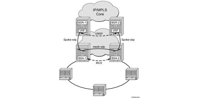
Figure 391 shows a typical ring-based configuration of network model based on the Layer 2 CO model.
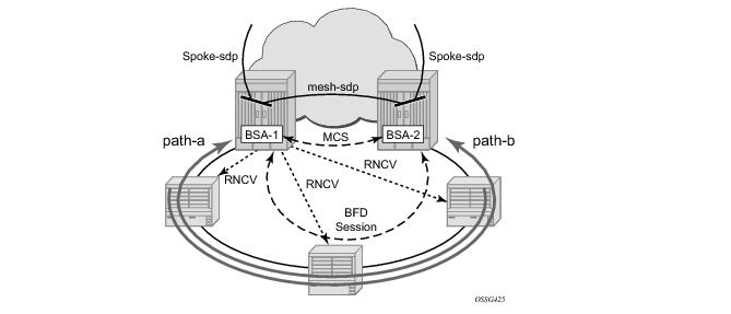
Figure 392 illustrates the detailed operation of the dual-homed ring. The steady-state is achieved under following conditions:
Under the above conditions, the ring is fully closed and every access node (the ring-node) has two possible paths toward the VPLS core.
Figure 392 refers to them as
path-a and
path-b. In order to avoid the loop created by the ring, only one of the paths may be used by any given ring-node for any given VLAN. The assignment of the individual VLANs to path-a or path-b, respectively, has to be provisioned on both BSAs in a consistent manner. The BSA with a lower IP address in the interface used for BFD will be the master for the VLANs associated with path-a and standby for the VLANs associated with path-b.
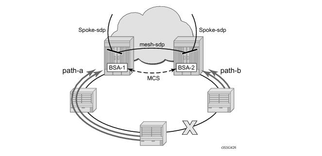
Figure 393 illustrates the scenario with the broken ring (link failure or ring-node failure). This state is reached under following conditions:
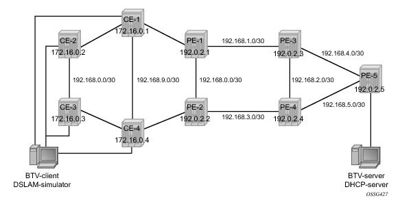
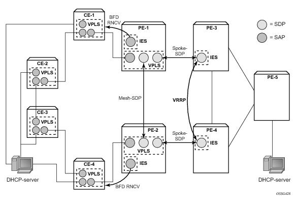
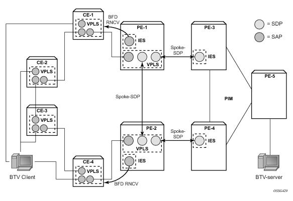
The network topology is displayed in Figure 394. The setup consists of two BSA nodes (PE-1 and PE-2), two BSR nodes (PE-3, PE-4) and another PE router (PE-5). A setup with one BSR node and two BSA nodes can also be used, but in this example, two (2) BSR nodes were used to show the typical Layer 2-CO setup with VRRP and Protocol Independent Multicast (PIM) on the BSRs. The access ring consists of four CE nodes.
configure system time
ntp
server 10.30.30.30 prefer
no shutdown
exit
exit all
configure
port 1/1/1
ethernet
mode access
encap-type qinq
exit
no shutdown
exit
port 1/1/2
ethernet
mode access
encap-type qinq
exit
no shutdown
exit
service
vpls 1 customer 1 create
interface "lo1" create
address 172.16.0.1/24
exit
sap 1/1/1:1.0 create
exit
sap 1/1/2:1.0 create
exit
no shutdown
exit
exit all
An interface lo1 is created in the VPLS. This interface will be used for RNCV.
configure
port 1/1/1
ethernet
mode access
encap-type qinq
exit
no shutdown
exit
service
ies 1 customer 1 create
interface "bfd-rncv1" create
address 172.16.0.251/24
bfd 100 receive 100 multiplier 3
sap 1/1/1:1.0 create
exit
exit
no shutdown
exit
exit all
configure
port 1/1/2
ethernet
mode access
encap-type qinq
exit
no shutdown
exit
service
ies 1 customer 1 create
interface "bfd-rncv1" create
address 172.16.0.252/24
bfd 100 receive 100 multiplier 3
sap 1/1/2:1.0 create
exit
exit
no shutdown
exit
exit all
Configure Multi-Chassis Synchronization (MCS) on the BSA nodes. Enable MCS for igmp-snooping,
mc-ring and
sub-mgmt. The configuration of PE-1 is shown below. The configuration of PE-2 is similar.
configure redundancy multi-chassis peer 192.0.2.2 create
sync
igmp-snooping
mc-ring
sub-mgmt
port 1/1/1 sync-tag "l2ring1" create
exit
no shutdown
exit
no shutdown
exit all
configure redundancy multi-chassis peer 192.0.2.2 create
mc-ring
ring "l2ring1" create
in-band-control-path
service-id 1
interface "bfd-rncv1"
dst-ip 172.16.0.252
exit
no shutdown
exit
exit
no shutdown
exit all
A:PE-1# show redundancy multi-chassis mc-ring peer 192.0.2.2 ring l2ring1 detail
===============================================================================
Multi-Chassis MC-Ring Detailed Information
===============================================================================
Peer : 192.0.2.2
Ring Type : Layer 2
Sync Tag : l2ring1
Port ID : 1/1/1
Admin State : inService
Oper State : connected
Admin Change : 11/05/2009 21:17:54
Oper Change : 11/05/2009 21:17:54
Failure Reason : None
Control B Path : No
-------------------------------------------------------------------------------
In Band Control Path
-------------------------------------------------------------------------------
Service ID : 1
Interface Name : bfd-rncv1
Oper State : connected
Dest IP : 172.16.0.252
Src IP : 172.16.0.251
...
configure redundancy multi-chassis peer 192.0.2.2 mc-ring ring l2ring1
ring-node "CE-1" create
connectivity-verify
dst-ip 172.16.0.1
interval 1
service-id 1
vlan 1
no shutdown
exit
exit
exit all
Note that the interval parameter is the interval used to check the reachability of the CE nodes (configurable from 1 to 6000 minutes). A BFD failure will also be a trigger for a reachability check.
configure redundancy multi-chassis peer 192.0.2.2 mc-ring ring l2ring1
path-b
range 3-3
exit
exit all
A:PE-1# show redundancy multi-chassis all
===============================================================================
Multi-Chassis Peers
===============================================================================
Peer IP Src IP Auth Peer Admin MC-Ring Oper MC-EP Adm
MCS Admin MCS Oper MCS State MC-LAG Adm MC-LAG Oper
-------------------------------------------------------------------------------
192.0.2.2 192.0.2.1 None Enabled inService --
Enabled Enabled inSync Disabled Disabled
===============================================================================
A:PE-1# show redundancy multi-chassis mc-ring peer 192.0.2.2 ring l2ring1 detail
===============================================================================
Multi-Chassis MC-Ring Detailed Information
===============================================================================
Peer : 192.0.2.2
Ring Type : Layer 2
Sync Tag : l2ring1
Port ID : 1/1/1
Admin State : inService
Oper State : connected
Admin Change : 11/05/2009 21:22:29
Oper Change : 11/05/2009 21:22:29
Failure Reason : None
Control B Path : No
-------------------------------------------------------------------------------
In Band Control Path
-------------------------------------------------------------------------------
Service ID : 1
Interface Name : bfd-rncv1
Oper State : connected
Dest IP : 172.16.0.252
Src IP : 172.16.0.251
Debounce State : inService
Debounce Max : 10 s
Debounce Guard : 60 s
-------------------------------------------------------------------------------
VLAN Managed Range
-------------------------------------------------------------------------------
full range
-------------------------------------------------------------------------------
VLAN Map B Path Provisioned
-------------------------------------------------------------------------------
range 3-3
-------------------------------------------------------------------------------
VLAN Map Excluded Path Provisioned
-------------------------------------------------------------------------------
no range
-------------------------------------------------------------------------------
VLAN Map B Path Operational
-------------------------------------------------------------------------------
range 3-3
-------------------------------------------------------------------------------
VLAN Map Excluded Path Operational
-------------------------------------------------------------------------------
no range
The output above shows that the ring l2ring1 on port 1/1/1 is in service and connected. Ring-node Connectivity Check (BFD) is running on
interface bfd-rncv1 in service
1. All VLANs on port 1/1/1 use path-a (default) except VLAN 3, which uses path-b.
A:PE-1# show redundancy multi-chassis mc-ring peer 192.0.2.2 ring l2ring1 ring-node
==============================================================================
MC-Ring Node entries
==============================================================================
Name Loc Oper St. Failure Reason
In Use Rem Oper St.
------------------------------------------------------------------------------
CE-1 connected None
No notTested
CE-2 connected None
No notTested
CE-3 connected None
No notTested
CE-4 connected None
No notTested
------------------------------------------------------------------------------
No. of MC-Ring Node entries: 4
==============================================================================
A:PE-1#
A:PE-1# show redundancy multi-chassis mc-ring peer 192.0.2.2 ring l2ring1 ring-node CE-1 detail
===============================================================================
Multi-Chassis MC-Ring Node Detailed Information
===============================================================================
Peer : 192.0.2.2
Sync Tag : l2ring1
Node Name : CE-1
Oper State Loc : connected
Oper State Rem : notTested
In Use : False
Admin Change : 11/05/2009 21:21:30
Oper Change : 11/05/2009 21:22:32
Failure Reason : None
-------------------------------------------------------------------------------
Ring Node Connectivity Verification
-------------------------------------------------------------------------------
Admin State : inService
Service ID : 1
Encap Value : 1
Dest IP : 172.16.0.1
Src IP : None
Interval : 1 minutes
Src MAC : None
===============================================================================
A:PE-1#
Figure 395 shows the logical setup of the services that will be created. Note that a mesh SDP is used between PE-1 and PE-2. A spoke SDP could also be used.
configure service
vpls 2 customer 1 create
description "VLAN_2"
split-horizon-group "RSHG" residential-group create
exit
sap 1/1/1:2.* split-horizon-group "RSHG" create
dhcp
snoop
lease-populate 10
no shutdown
exit
anti-spoof ip-mac
sub-sla-mgmt
def-sub-profile "initial"
def-sla-profile "initial"
sub-ident-policy "speedy"
multi-sub-sap 10
no shutdown
exit
exit
mesh-sdp 12:2 create
dhcp
snoop
exit
exit
spoke-sdp 13:2 create
dhcp
snoop
exit
exit
no shutdown
exit
exit all
configure subscriber-mgmt
sla-profile "initial" create
exit
sub-profile "initial" create
exit
sub-ident-policy "speedy" create
strings-from-option 254
exit
exit all
configure service
vpls 2 customer 1 create
sap 1/1/1:2.* create
exit
sap 1/1/2:2.* create
exit
sap 1/1/3:2.* create
exit
no shutdown
exit
exit all
configure service
ies 2 customer 1 create
interface "VLAN_2" create
address 10.0.2.3/24
dhcp
server 10.10.10.10
trusted
no shutdown
exit
ip-mtu 1500
vrrp 2
backup 10.0.2.254
ping-reply
exit
local-proxy-arp
spoke-sdp 31:2 create
exit
exit
no shutdown
exit
exit all
configure service
ies 2 customer 1 create
interface "VLAN_2" create
address 10.0.2.4/24
dhcp
server 10.10.10.10
trusted
no shutdown
exit
ip-mtu 1500
vrrp 2
backup 10.0.2.254
ping-reply
exit
local-proxy-arp
spoke-sdp 42:2 create
exit
exit
no shutdown
exit
exit all
configure service
ies 2 customer 1 create
interface "dhcp-server" create
address 192.168.6.1/30
sap 1/1/3:2 create
exit
exit
no shutdown
exit
exit all
A:PE-1# show service id 2 dhcp lease-state
===============================================================================
DHCP lease state table, service 2
===============================================================================
IP Address Mac Address Sap/Sdp Id Remaining Lease MC
LifeTime Origin Stdby
-------------------------------------------------------------------------------
10.0.2.107 00:00:64:01:01:02 1/1/1:2.* 09d07h38m DHCP
-------------------------------------------------------------------------------
Number of lease states : 1
===============================================================================
A:PE-1# show service active-subscribers
===============================================================================
Active Subscribers
===============================================================================
-------------------------------------------------------------------------------
Subscriber subscriber_1_vlan_2 (initial)
-------------------------------------------------------------------------------
-------------------------------------------------------------------------------
(1) SLA Profile Instance sap:1/1/1:2.* - sla:initial
-------------------------------------------------------------------------------
IP Address MAC Address PPPoE-SID Origin
-------------------------------------------------------
10.0.2.107 00:00:64:01:01:02 N/A DHCP
-------------------------------------------------------------------------------
Number of active subscribers : 1
===============================================================================
A:PE-1# show service active-subscribers subscriber subscriber_1_vlan_2 detail
===============================================================================
Active Subscribers
===============================================================================
-------------------------------------------------------------------------------
Subscriber subscriber_1_vlan_2 (initial)
-------------------------------------------------------------------------------
I. Sched. Policy : N/A
E. Sched. Policy : N/A E. Agg Rate Limit: Max
Q Frame-Based Ac*: Disabled
Acct. Policy : N/A Collect Stats : Disabled
Rad. Acct. Pol. : N/A
Dupl. Acct. Pol. : N/A
ANCP Pol. : N/A
HostTrk Pol. : N/A
Sub. ANCP-String : "subscriber_1_vlan_2"
Sub. Int Dest Id : "CE-1"
Host Trk Rate Adj: N/A
-------------------------------------------------------------------------------
(1) SLA Profile Instance
- sap:1/1/1:2.* (VPLS 2)
- sla:initial
-------------------------------------------------------------------------------
Description : (Not Specified)
Host Limit : No Limit
Ingress Qos-Policy : 1 Egress Qos-Policy : 1
Ingress Queuing Type : Service-queuing
Ingress Filter-Id : N/A Egress Filter-Id : N/A
Ingress Report-Rate : N/A
Egress Report-Rate : N/A
Egress Remarking : from Sap Qos
Credit Control Pol. : N/A
-------------------------------------------------------------------------------
-------------------------------------------------------------------------------
IP Address MAC Address PPPoE-SID Origin
-------------------------------------------------------
10.0.2.107 00:00:64:01:01:02 N/A DHCP
A:PE-1# show redundancy multi-chassis sync peer 192.0.2.2
===============================================================================
Multi-chassis Peer Table
===============================================================================
Peer
-------------------------------------------------------------------------------
Peer IP Address : 192.0.2.2
Description : (Not Specified)
Authentication : Disabled
Source IP Address : 192.0.2.1
Admin State : Enabled
-------------------------------------------------------------------------------
Sync-status
-------------------------------------------------------------------------------
Client Applications : IGMPSnooping SUBMGMT RING
Sync Admin State : Up
Sync Oper State : Up
DB Sync State : inSync
Num Entries : 11
Lcl Deleted Entries : 0
Alarm Entries : 0
Rem Num Entries : 11
Rem Lcl Deleted Entries : 0
Rem Alarm Entries : 0
===============================================================================
MCS Application Stats
===============================================================================
Application : igmp
Num Entries : 0
Lcl Deleted Entries : 0
Alarm Entries : 0
-------------------------------------------------------------------------------
Rem Num Entries : 0
Rem Lcl Deleted Entries : 0
Rem Alarm Entries : 0
-------------------------------------------------------------------------------
Application : igmpSnooping
Num Entries : 0
Lcl Deleted Entries : 0
Alarm Entries : 0
-------------------------------------------------------------------------------
Rem Num Entries : 0
Rem Lcl Deleted Entries : 0
Rem Alarm Entries : 0
-------------------------------------------------------------------------------
Application : subMgmt
Num Entries : 1
Lcl Deleted Entries : 0
Alarm Entries : 0
-------------------------------------------------------------------------------
Rem Num Entries : 1
Rem Lcl Deleted Entries : 0
Rem Alarm Entries : 0
-------------------------------------------------------------------------------
Application : srrp
Num Entries : 0
Lcl Deleted Entries : 0
Alarm Entries : 0
-------------------------------------------------------------------------------
Rem Num Entries : 0
Rem Lcl Deleted Entries : 0
Rem Alarm Entries : 0
-------------------------------------------------------------------------------
Application : mcRing
Num Entries : 10
Lcl Deleted Entries : 0
Alarm Entries : 0
-------------------------------------------------------------------------------
Rem Num Entries : 10
Rem Lcl Deleted Entries : 0
Rem Alarm Entries : 0
-------------------------------------------------------------------------------
Application : mldSnooping
Num Entries : 0
Lcl Deleted Entries : 0
Alarm Entries : 0
-------------------------------------------------------------------------------
Rem Num Entries : 0
Rem Lcl Deleted Entries : 0
Rem Alarm Entries : 0
-------------------------------------------------------------------------------
Application : dhcpServer
Num Entries : 0
Lcl Deleted Entries : 0
Alarm Entries : 0
-------------------------------------------------------------------------------
Rem Num Entries : 0
Rem Lcl Deleted Entries : 0
Rem Alarm Entries : 0
-------------------------------------------------------------------------------
Application : subHostTrk
Num Entries : 0
Lcl Deleted Entries : 0
Alarm Entries : 0
-------------------------------------------------------------------------------
Rem Num Entries : 0
Rem Lcl Deleted Entries : 0
Rem Alarm Entries : 0
-------------------------------------------------------------------------------
===============================================================================
A:PE-1#
A:PE-2# show service id 2 dhcp lease-state
===============================================================================
DHCP lease state table, service 2
===============================================================================
IP Address Mac Address Sap/Sdp Id Remaining Lease MC
LifeTime Origin Stdby
-------------------------------------------------------------------------------
10.0.2.107 00:00:64:01:01:02 1/1/2:2.* 09d06h16m DHCP Yes
-------------------------------------------------------------------------------
Number of lease states : 1
===============================================================================
A:PE-2#
A:PE-1# show service id 2 sap 1/1/1:2.*
===============================================================================
Service Access Points(SAP)
===============================================================================
Service Id : 2
SAP : 1/1/1:2.* Encap : qinq
QinQ Dot1p : Default
Description : (Not Specified)
Admin State : Up Oper State : Up
Flags : None
Multi Svc Site : None
Last Status Change : 11/06/2009 17:17:26
Last Mgmt Change : 11/04/2009 22:51:15
===============================================================================
A:PE-2# show service id 2 sap 1/1/2:2.*
===============================================================================
Service Access Points(SAP)
===============================================================================
Service Id : 2
SAP : 1/1/2:2.* Encap : qinq
QinQ Dot1p : Default
Description : (Not Specified)
Admin State : Up Oper State : Down
Flags : StandByForMcRing
Multi Svc Site : None
Last Status Change : 11/06/2009 18:07:30
Last Mgmt Change : 11/04/2009 23:43:16
===============================================================================
A:PE-1# show redundancy multi-chassis mc-ring peer 192.0.2.2
==============================================================================
MC-Ring entries
==============================================================================
Sync Tag Oper State Failure Reason
------------------------------------------------------------------------------
l2ring1 broken None
------------------------------------------------------------------------------
No. of MC-Ring entries: 1
==============================================================================
A:PE-1# show redundancy multi-chassis mc-ring peer 192.0.2.2 ring l2ring1 ring-node
==============================================================================
MC-Ring Node entries
==============================================================================
Name Loc Oper St. Failure Reason
In Use Rem Oper St.
------------------------------------------------------------------------------
CE-1 connected None
Yes disconnected
CE-2 disconnected None
No connected
CE-3 disconnected None
No connected
CE-4 disconnected None
No connected
------------------------------------------------------------------------------
No. of MC-Ring Node entries: 4
==============================================================================
Notice that the SAPs on both PE-1 and PE-2 are now operationally up. This can be checked with the show service id 2 sap 1/1/1:2.* command on PE1 and the
show service id 2 sap 1/1/2:2.* command on PE2.
configure service
ies 3 customer 1 create
interface "mcast-server" create
address 192.168.7.1/30
sap 1/1/3:3 create
exit
exit
no shutdown
exit
exit all
configure service
vpls 4 customer 1 create
description "Multicast VLAN"
igmp-snooping
no shutdown
exit
sap 1/1/1:4.* create
exit
spoke-sdp 12:4 create
igmp-snooping
mrouter-port
exit
exit
spoke-sdp 13:4 create
igmp-snooping
mrouter-port
exit
exit
no shutdown
exit
exit all
configure service
ies 4 customer 1 create
interface "btv-dst" create
address 10.0.4.3/24
ip-mtu 1500
spoke-sdp 31:4 create
exit
exit
no shutdown
exit
exit all
configure service
ies 4 customer 1 create
interface "btv-dst" create
address 10.0.4.4/24
ip-mtu 1500
spoke-sdp 42:4 create
exit
exit
no shutdown
exit
exit all
Notice that also here the ip-mtu must be configured to bring the service up. The
ip-mtu is required to have an MTU match on the spoke SDP between the IES service and the VPLS service.
configure router pim
interface "system"
exit
interface "int-PE-3-PE-4"
priority 10
exit
interface "int-PE-3-PE-5"
exit
interface "btv-dst"
exit
rp
static
address 192.0.2.5
group-prefix 224.0.0.0/4
exit
exit
exit
exit all
configure router igmp interface btv-dst no shutdown
configure service
vpls 4 customer 1 create
sap 1/1/1:4.* create
exit
sap 1/1/2:4.* create
exit
sap 1/1/3:4.* create
exit
no shutdown
exit
exit all
A:PE-1# show service id 4 mfib
===============================================================================
Multicast FIB, Service 4
===============================================================================
Source Address Group Address Sap/Sdp Id Svc Id Fwd/Blk
-------------------------------------------------------------------------------
* * sdp:12:4 Local Fwd
sdp:13:4 Local Fwd
* 225.1.1.1 sap:1/1/1:4.* Local Fwd
sdp:12:4 Local Fwd
sdp:13:4 Local Fwd
-------------------------------------------------------------------------------
Number of entries: 2
===============================================================================
A:PE-3# show router igmp group
===============================================================================
IGMP Groups
===============================================================================
(*,225.1.1.1) Up Time : 0d 00:01:03
Fwd List : btv-dst
-------------------------------------------------------------------------------
(*,G)/(S,G) Entries : 1
===============================================================================
A:PE-1# show redundancy multi-chassis sync peer 192.0.2.2 detail
===============================================================================
Multi-chassis Peer Table
===============================================================================
Peer
-------------------------------------------------------------------------------
Peer IP Address : 192.0.2.2
Description : (Not Specified)
Authentication : Disabled
Source IP Address : 192.0.2.1
Admin State : Enabled
-------------------------------------------------------------------------------
Sync-status
-------------------------------------------------------------------------------
Client Applications : IGMPSnooping SUBMGMT RING
Sync Admin State : Up
Sync Oper State : Up
DB Sync State : inSync
Num Entries : 12
Lcl Deleted Entries : 0
Alarm Entries : 0
Rem Num Entries : 12
Rem Lcl Deleted Entries : 0
Rem Alarm Entries : 0
===============================================================================
MCS Application Stats
===============================================================================
Application : igmp
Num Entries : 1
Lcl Deleted Entries : 0
Alarm Entries : 0
-------------------------------------------------------------------------------
Rem Num Entries : 1
Rem Lcl Deleted Entries : 0
Rem Alarm Entries : 0
A:PE-2# show service id 4 mfib
===============================================================================
Multicast FIB, Service 4
===============================================================================
Source Address Group Address Sap/Sdp Id Svc Id Fwd/Blk
-------------------------------------------------------------------------------
* * sdp:21:4 Local Fwd
sdp:24:4 Local Fwd
* 225.1.1.1 sap:1/1/2:4.* Local Fwd
sdp:21:4 Local Fwd
sdp:24:4 Local Fwd
-------------------------------------------------------------------------------
Number of entries: 2
===============================================================================
A:PE-2#
A:PE-2# show service id 4 sap 1/1/2:4.*
===============================================================================
Service Access Points(SAP)
===============================================================================
Service Id : 4
SAP : 1/1/2:4.* Encap : qinq
QinQ Dot1p : Default
Description : (Not Specified)
Admin State : Up Oper State : Down
Flags : StandByForMcRing
Multi Svc Site : None
Last Status Change : 11/06/2009 18:56:25
Last Mgmt Change : 11/04/2009 23:43:16
===============================================================================