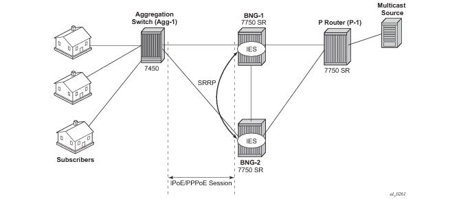
The network topology displayed in Figure 343 shows a typical TPSDA setup. It consists of three 7750s and a single 7450. Two 7750s are configured as Broadband Network Gateways (BNGs) and the third 7750 is configured as a
P router. The 7450 is used as an aggregation switch to aggregate all subscribers.
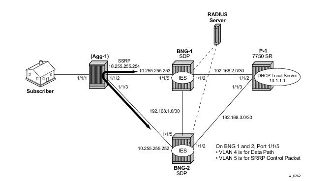
Figure 344 shows the addressing scheme used in the setup. The example uses numbered SRRP subscriber interfaces with static SAPs serving both IPoE and PPPoE subscribers. The configuration of the RADIUS server is out of the scope of this example.
*A:BNG-1>config>service>ies# info
----------------------------------------------
description "BNG-1"
redundant-interface "MClink-BNG-1-BNG-2" create
address 192.168.1.0/31
ip-mtu 1500
spoke-sdp 1:1 create
no shutdown
exit
exit
interface "Int-BNG-1-P-1" create
address 192.168.2.1/30
sap 1/1/2 create
no shutdown
exit
exit
subscriber-interface "sub-int-1" create
address 10.255.255.253/8 gw-ip-address 10.255.255.254 track-srrp 1
group-interface "group-int-1" create
dhcp
server 192.168.0.1
lease-populate 10
client-applications dhcp ppp
gi-address 10.255.255.253
no shutdown
exit
authentication-policy "auth-policy-1"
redundant-interface "MClink-BNG-1-BNG-2"
sap 1/1/5:4 create
sub-sla-mgmt
def-sub-id use-sap-id
def-sub-profile "multicast-profile-1"
def-sla-profile "sla-profile-1"
sub-ident-policy "sub-ident-policy-1"
multi-sub-sap 10
no shutdown
exit
exit
sap 1/1/5:5 create
exit
srrp 1 create
message-path 1/1/5:5
priority 100
no shutdown
exit
pppoe
no shutdown
exit
exit
exit
A:BNG-1>config>router# info
ospf
traffic-engineering
area 0.0.0.0
interface "system"
no shutdown
exit
interface "int-BNG-1-BNG-2"
interface-type point-to-point
metric 10000
no shutdown
exit
interface "sub-int-1"
no shutdown
exit
interface "int-BNG-1-P-1"
no shutdown
exit
exit
exit
pim
interface "nt-BNG-1-P-1
exit
no shutdown
*A:BNG-2>config>service>ies# info
----------------------------------------------
description "BNG-2"
redundant-interface "MClink-BNG-2-BNG-1" create
address 192.168.1.1/31
ip-mtu 1500
spoke-sdp 1:1 create
no shutdown
exit
exit
interface "int-BNG-2-P-1" create
address 192.168.3.1/30
sap 1/1/2 create
no shutdown
exit
exit
subscriber-interface "sub-int-1" create
address 10.255.255.252/8 gw-ip-address 10.255.255.254 track-srrp 1
group-interface "group-int-1" create
dhcp
server 192.168.0.1
lease-populate 10
client-applications dhcp ppp
gi-address 10.255.255.252
no shutdown
exit
authentication-policy "auth-policy-1"
redundant-interface "MClink-BNG-2-BNG-1"
sap 1/1/5:4 create
sub-sla-mgmt
def-sub-id use-sap-id
def-sub-profile "multicast-profile-1"
def-sla-profile "sla-profile-1"
sub-ident-policy "sub-ident-policy-1"
multi-sub-sap 10
no shutdown
exit
exit
sap 1/1/5:5 create
exit
srrp 1 create
message-path 1/1/5:5
no shutdown
exit
pppoe
no shutdown
exit
exit
exit
*A:BNG-2>config>router# info
ospf
traffic-engineering
area 0.0.0.0
interface "system"
no shutdown
exit
interface "int-BNG-2-BNG-1"
interface-type point-to-point
metric 10000
no shutdown
exit
interface "sub-int-1"
no shutdown
exit
interface "int-BNG-2-P-1"
no shutdown
exit
exit
exit
pim
interface "int-BNG-2-P-1"
exit
no shutdown
exit
*A:Agg-1>config>service>info
vpls 1 customer 1 create
sap 1/1/2:5 create
no shutdown
exit
sap 1/1/3:5 create
no shutdown
exit
no shutdown
exit
vpls 2 customer 1 create
sap 1/1/2:4 create
no shutdown
exit
sap 1/1/3:4 create
no shutdown
exit
sap 1/1/1:4 create
no shutdown
exit
no shutdown
exit
*A:P-1>config>router>info
#--------------------------------------------------
echo "Local DHCP Server Configuration"
#--------------------------------------------------
dhcp
local-dhcp-server "dhcp-local-server" create
use-gi-address scope pool
pool "pool-1" create
subnet 10.0.0.0/8 create
options
subnet-mask 255.0.0.0
default-router 10.255.255.254
exit
address-range 10.0.0.10 10.0.0.254
exit
exit
no shutdown
exit
exit
#--------------------------------------------------
echo "IP Configuration"
#--------------------------------------------------
interface "dhcp-lb1"
address 192.168.0.1/32
loopback
local-dhcp-server "dhcp-local-server
no shutdown
exit
interface "int-P-1-BNG-1"
address 192.168.2.2/30
port 1/1/2
no shutdown
exit
interface "int-P-1-BNG-2"
address 192.168.3.2/30
port 1/1/3
no shutdown
exit
interface "P-1-multicast-source"
address 192.168.4.1/30
port 1/1/1
no shutdown
exit
interface "system"
address 192.0.2.3/32
no shutdown
exit
#--------------------------------------------------
ospf
area 0.0.0.0
interface "system"
no shutdown
exit
interface "int-P-1-BNG-1"
no shutdown
exit
interface "int-P-1-BNG-2"
no shutdown
exit
interface "P-1-multicast-source"
no shutdown
exit
exit
exit
pim
interface "int-P-1-BNG-1"
exit
interface "int-P-1-BNG-2"
exit
interface "P-1-multicast-source"
exit
exit
*A:BNG-1>config>router>igmp# info
----------------------------------------------
group-interface "group-int-1"
no shutdown
exit
[no] disable-router* - Enable/disable the IGMP router alert check option
[no] import - Import a policy to filter IGMP packets
[no] max-groups - Configure the maximum number of groups for this
group-interface
[no] max-grp-sources - Configure the maximum number of group sources for this
group-interface
[no] max-sources - Configure the maximum number of sources for this
group-interface
[no] mcac + Configure multicast CAC policy and constraints for this
interface
[no] shutdown - Administratively enable/disable the interface
[no] sub-hosts-only - Enable/disable the IGMP traffic from known hosts only
[no] subnet-check - Enable/disable local subnet checking for IGMP
[no] version - Configure the version of IGMP
*A:BNG-1> config subscr-mgmt
igmp-policy "igmp-policy-1" create
exit
*A:BNG-1> config subscr-mgmt
sub-prof "multicast-profile-1"
igmp-policy "igmp-policy-1"
[no] description - Description for the IGMP policy
[no] egress-rate-mo* - Configure the egress rate modification
[no] fast-leave - Enable/disable IGMP fast-leave processing
[no] import - Specify the import policy to filter IGMP packets
[no] max-num-groups - Configure the max number of multicast groups
[no] max-num-grp-so* - Configure the max number of multicast group sources
[no] max-num-sources - Configure the max number of multicast sources
[no] mcast-reporting + Configure the mcast reporting
[no] per-host-repli* - Enable/disable IGMP per-host-replication processing
[no] redirection-po* - Specify the IGMP redirection policy
static + Add/remove IGMP static group membership
[no] version - Configure the version of IGMP
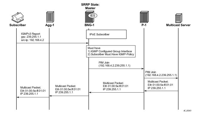
With the baseline configuration applied, the BNG is ready to process IGMP messages and deliver multicast. Figure 345 shows a flow for IPoE subscribers requesting and receiving multicast traffic. The key items are highlighted in dotted box:
To verify that the group interface is ready for multicast, use the show command as indicated below. Remember that the IES service id is 1 and the group-interface name is
group-int-1.
*A:BNG-1> show router igmp group-interface
===============================================================================
IGMP Group-Interfaces
===============================================================================
FwdSvc Group-Interface Adm/Opr-State Import-Policy
SAP Adm/Opr-Version Num-Groups
-------------------------------------------------------------------------------
1 group-int-1 Up/Up none
1/1/5:4 3/3 0
-------------------------------------------------------------------------------
Group-Interfaces = 1, SAPs = 1
===============================================================================
*A:BNG-1> show subscriber-mgmt sub-profile "multicast-profile-1"
===============================================================================
Subscriber Profile multicast-profile-1
===============================================================================
Description : (Not Specified)
I. Sched. Policy : N/A
E. Sched. Policy : N/A E. Agg Rate Limit: Max
I. Policer Ctrl. : N/A
E. Policer Ctrl. : N/A
Q Frame-Based Ac*: Disabled
Acct. Policy : N/A Collect Stats : Disabled
Rad. Acct. Pol. : N/A
Dupl. Acct. Pol. : N/A
ANCP Pol. : N/A
HostTrk Pol. : N/A
IGMP Policy : igmp-policy-1
Sub. MCAC Policy : N/A
NAT Policy : N/A
Def. Encap Offset: none Encap Offset Mode: none
Avg Frame Size : N/A
Preference : 5
-------------------------------------------------------------------------------
HSMDA-2
-------------------------------------------------------------------------------
I. Qos Policy : 1 E. Qos Policy : 1
E. Agg Rate Limit: Max
E. WRR Policy : N/A Pkt Byte Offset : add 0*
-------------------------------------------------------------------------------
Last Mgmt Change : 05/14/2013 10:12:49
===============================================================================
* indicates that the corresponding row element may have been truncated.
*A:BNG-1> show router igmp group
===============================================================================
IGMP Interface Groups
===============================================================================
===============================================================================
IGMP Host Groups
===============================================================================
===============================================================================
IGMP SAP Groups
===============================================================================
(192.168.4.2,239.255.1.1)
Fwd List : 1/1/5:4 Up Time : 0d 00:00:08
-------------------------------------------------------------------------------
(*,G)/(S,G) Entries : 1
===============================================================================
*A:BNG-1> show router igmp group-interface detail
===============================================================================
IGMP Group-Interfaces
===============================================================================
FwdSvc/Grp-Intf : 1/group-int-1
Admin-Status : Up Oper-Status : Up
Import-Policy : none Subnet-Check : Disabled
Router-Alert-Check : Enabled Sub-Hosts-Only : Disabled
MCAC Policy Name : MCAC Const Adm St : Enable
MCAC Max Unconst BW: no limit MCAC Max Mand BW : no limit
MCAC In use Mand BW: 0 MCAC Avail Mand BW : unlimited
MCAC In use Opnl BW: 0 MCAC Avail Opnl BW : unlimited
-------------------------------------------------------------------------------
SAP : 1/1/5:4
Admin/Oper version: 3/3 Num Groups : 1
Max Groups Allowed: No Limit Max Groups Till Now: 1
Max Sources Allow*: No Limit
Max Grp Srcs Allo*: No Limit
-------------------------------------------------------------------------------
Group-Address : 239.255.1.1 Up Time : 0d 00:04:05
Expires : N/A Mode : include
V1 Host Timer : Not running Type : dynamic
V2 Host Timer : Not running Compat Mode : IGMP Version 3
------------------------------------------------------------------
GrpSrc-Address Expires Type Fwd/Blk
------------------------------------------------------------------
192.168.4.2 0d 00:03:50 dynamic Fwd
-------------------------------------------------------------------------------
Group-Interfaces = 1, SAPs = 1
===============================================================================
* indicates that the corresponding row element may have been truncated.
*A:BNG-1> show service active-subscribers igmp detail
===============================================================================
Active Subscribers Detail
===============================================================================
Subscriber IGMP-Policy
HostAddr GrpItf NumGroups
GrpAddr Type Up-Time Mode
SrcAddr Type Blk/Fwd
-------------------------------------------------------------------------------
Subscriber-1 igmp-policy-1
-------------------------------------------------------------------------------
Number of Subscribers : 1
*A:BNG-1> show subscriber-mgmt igmp-policy "igmp-policy-1"
===============================================================================
IGMP Policy igmp-policy-1
===============================================================================
Import Policy :
Admin Version : 3
Num Subscribers : 0
Host Max Group : No Limit
Host Max Sources : No Limit
Host Max Group Sources : No Limit
Fast Leave : yes
Redirection Policy :
Per Host Replication : no
Egress Rate Modify : no
Mcast Reporting Destination Name :
Mcast Reporting Admin State : Disabled
===============================================================================
*A:BNG-1> show router igmp hosts detail
===============================================================================
IGMP Host 10.0.0.24
===============================================================================
Oper Status : Up MacAddress : 00:00:10:10:10:11
Oper version : 3 Subscriber : Subscriber-1
Num Groups : 1 GrpItf : group-int-1
Max Grps Till Now: 1 IGMP-Policy : igmp-policy-1
PPPoE SessionId : N/A Next query time: 0d 00:01:52
FwdSvcId : 1 Max Srcs Allow*: No Limit
Max Grps Allowed : No Limit Max Grp Srcs A*: No Limit
-------------------------------------------------------------------------------
IGMP Group
-------------------------------------------------------------------------------
Group Address : 239.255.1.1 Up Time : 0d 00:02:46
Expires : Not running Mode : Include
V1 Host Timer : Not running Type : Dynamic
V2 Host Timer : Not running Compat Mode: IGMP Version 3
Redir.SvcId : N/A Redir.Intf : N/A
-----------------------------------------------------------
Source Address Expires Type Fwd/Blk
-----------------------------------------------------------
192.168.4.2 0d 00:04:09 Dynamic Fwd
-------------------------------------------------------------------------------
Hosts : 1
*A:BNG-1> show service active-subscribers igmp subscriber "Subscriber-2" detail
===============================================================================
Active Subscribers Detail
===============================================================================
Subscriber IGMP-Policy
HostAddr GrpItf NumGroups
GrpAddr Type Up-Time Mode
SrcAddr Type Blk/Fwd
-------------------------------------------------------------------------------
Subscriber-1 igmp-policy-1
10.0.0.24 group-int-1 1
239.255.1.1 Dynamic 0d 00:01:26 Include
192.168.4.2 Dynamic Fwd
-------------------------------------------------------------------------------
Number of Subscribers : 1
===============================================================================
*A:BNG-1> show router igmp group-interface detail
===============================================================================
IGMP Group-Interfaces
===============================================================================
FwdSvc/Grp-Intf : 1/group-int-1
Admin-Status : Up Oper-Status : Up
Import-Policy : none Subnet-Check : Enabled
Router-Alert-Check : Enabled Sub-Hosts-Only : Enabled
MCAC Policy Name : MCAC Const Adm St : Enable
MCAC Max Unconst BW: no limit MCAC Max Mand BW : no limit
MCAC In use Mand BW: 0 MCAC Avail Mand BW : unlimited
MCAC In use Opnl BW: 0 MCAC Avail Opnl BW : unlimited
-------------------------------------------------------------------------------
SAP : 1/1/5:4
Admin/Oper version: 3/3 Num Groups : 0
Max Groups Allowed: No Limit Max Groups Till Now: 0
Max Sources Allow*: No Limit
Max Grp Srcs Allo*: No Limit
-------------------------------------------------------------------------------
Group-Interfaces = 1, SAPs = 1
===============================================================================
* indicates that the corresponding row element may have been truncated.
*A:BNG-1> show router igmp group
===============================================================================
IGMP Interface Groups
===============================================================================
===============================================================================
IGMP Host Groups
===============================================================================
(192.168.4.2,239.255.1.1)
Fwd List : 10.0.0.12 Up Time : 0d 17:19:08
===============================================================================
IGMP SAP Groups
===============================================================================
-------------------------------------------------------------------------------
(*,G)/(S,G) Entries : 1
===============================================================================
*A:BNG-1> show router igmp hosts detail
===============================================================================
IGMP Host 10.0.0.12
===============================================================================
Oper Status : Up MacAddress : 52:e0:50:bd:00:00
Oper version : 3 Subscriber : User-ppp-1
Num Groups : 1 GrpItf : group-int-1
Max Grps Till Now: 1 IGMP-Policy : igmp-policy-1
PPPoE SessionId : 1 Next query time: 0d 00:01:47
FwdSvcId : 1 Max Srcs Allow*: No Limit
Max Grps Allowed : No Limit Max Grp Srcs A*: No Limit
-------------------------------------------------------------------------------
IGMP Group
-------------------------------------------------------------------------------
Group Address : 239.255.1.1 Up Time : 0d 00:00:36
Expires : Not running Mode : Include
V1 Host Timer : Not running Type : Dynamic
V2 Host Timer : Not running Compat Mode: IGMP Version 3
Redir.SvcId : N/A Redir.Intf : N/A
-----------------------------------------------------------
Source Address Expires Type Fwd/Blk
-----------------------------------------------------------
192.168.4.2 0d 00:04:03 Dynamic Fwd
-------------------------------------------------------------------------------
Hosts : 1
===============================================================================
* indicates that the corresponding row element may have been truncated.
*A:BNG-1> show service active-subscribers igmp subscriber "user02" detail
===============================================================================
Active Subscribers Detail
===============================================================================
Subscriber IGMP-Policy
HostAddr GrpItf NumGroups
GrpAddr Type Up-Time Mode
SrcAddr Type Blk/Fwd
-------------------------------------------------------------------------------
User-ppp-1 igmp-policy-1
10.0.0.12 group-int-1 1
239.255.1.1 Dynamic 0d 00:02:07 Include
192.168.4.2 Dynamic Fwd
-------------------------------------------------------------------------------
Number of Subscribers : 1
===============================================================================
*A:BNG-1>config>redundancy# info
----------------------------------------------
multi-chassis
peer 192.0.2.2 create
sync
igmp
srrp
sub-mgmt ipoe pppoe
port 1/1/5 create
range 4-4 sync-tag "sub"
range 5-5 sync-tag "srrp"
exit
no shutdown
exit
no shutdown
exit
exit
*A:BNG-1> show redundancy multi-chassis sync peer 192.0.2.2 detail
===============================================================================
Multi-chassis Peer Table
===============================================================================
Peer
-------------------------------------------------------------------------------
Peer IP Address : 192.0.2.2
Description : (Not Specified)
Authentication : Disabled
Source IP Address : 192.0.2.1
Admin State : Enabled
-------------------------------------------------------------------------------
Sync-status
-------------------------------------------------------------------------------
Client Applications : IGMP SUBMGMT-IPOE SUBMGMT-PPPOE SRRP
Sync Admin State : Up
Sync Oper State : Up
DB Sync State : inSync
Num Entries : 15
Lcl Deleted Entries : 0
Alarm Entries : 0
Rem Num Entries : 15
Rem Lcl Deleted Entries : 0
Rem Alarm Entries : 0
===============================================================================
MCS Application Stats
===============================================================================
Application : igmp
Num Entries : 1
Lcl Deleted Entries : 0
Alarm Entries : 0
-------------------------------------------------------------------------------
Rem Num Entries : 1
Rem Lcl Deleted Entries : 0
Rem Alarm Entries : 0
-------------------------------------------------------------------------------
Application : subMgmtIpoe
Num Entries : 1
Lcl Deleted Entries : 0
Alarm Entries : 0
-------------------------------------------------------------------------------
Rem Num Entries : 1
Rem Lcl Deleted Entries : 0
Rem Alarm Entries : 0
-------------------------------------------------------------------------------
Application : srrp
Num Entries : 14
Lcl Deleted Entries : 0
Alarm Entries : 0
-------------------------------------------------------------------------------
Rem Num Entries : 14
Rem Lcl Deleted Entries : 0
Rem Alarm Entries : 0
-------------------------------------------------------------------------------
Application : subMgmtPppoe
Num Entries : 1
Lcl Deleted Entries : 0
Alarm Entries : 0
-------------------------------------------------------------------------------
Rem Num Entries : 1
Rem Lcl Deleted Entries : 0
Rem Alarm Entries : 0
-------------------------------------------------------------------------------
===============================================================================
*A:BNG-1> tools dump redundancy multi-chassis sync-database application igmp detail
If no entries are present for an application, no detail will be displayed.
FLAGS LEGEND: ld - local delete; da - delete alarm; pd - pending global delete
Peer Ip 192.0.2.2
Application IGMP
Sap-id Client Key
SyncTag DLen Flags timeStamp
deleteReason code and description
-------------------------------------------------------------------------------
1/1/5:4 Host=10.0.0.10, HostGroup=239.255.1.1
sub 20 -- -- -- 05/23/2013 13:05:31
0x0
The following totals are for:
peer ip ALL, port/lag ALL, sync-tag ALL, application IGMP
Valid Entries: 1
Locally Deleted Entries: 0
Locally Deleted Alarmed Entries: 0
Pending Global Delete Entries: 0
debug
router
igmp
packet mode egr-ingr-and-dropped
exit
exit
2977 2013/05/23 13:01:45.43 EST MINOR: DEBUG #2001 IGMP[9]
"IGMP[9]: RX-PKT
[012 03:58:58.090] IGMP host 10.0.0.10 V3 PDU: 10.0.0.10 -> 224.0.0.22 pduLen
20
Type: V3 REPORT maxrespCode 0x0 checkSum 0xddf7
Num Group Records: 1
Group Record 0
Type: ALW_NEW_SRCS, AuxDataLen 0, Num Sources 1
Mcast Addr: 239.255.1.1
Source Address List
192.168.4.2
"
debug
router
igmp
host "10.0.0.10"
exit
exit
2978 2013/05/23 13:01:45.43 EST MINOR: DEBUG #2001 ies1 IGMP[ies1 inst 9
]
"IGMP[ies1 inst 9]: igmpIfGroupAdd
Adding 239.255.1.1 to IGMP host 10.0.0.10 database"
2979 2013/05/23 13:01:45.43 EST MINOR: DEBUG #2001 ies1 IGMP[ies1 inst 9
]
"IGMP[ies1 inst 9]: igmpProcessGroupRec
Process group rec ALW_NEW_SRCS received on host 10.0.0.10 for group 239.255.1.1 i
n mode INCLUDE. Num srcs 1"
2980 2013/05/23 13:01:45.43 EST MINOR: DEBUG #2001 ies1 IGMP[ies1 inst 9
]
"IGMP[ies1 inst 9]: igmpIfSrcAdd
Adding i/f source entry for host 10.0.0.10 (192.168.4.2,239.255.1.1) to IGMP fwdList
Database, redir if N/A"
debug
router
igmp
mcs "group-int-1"
exit
exit
2981 2013/05/23 13:01:45.44 EST MINOR: DEBUG #2001 ies1 IGMP[ies1 inst 9
]
"IGMP[ies1 inst 9]: igmpMcsAddIfGroup
Building MCS entry for host 10.0.0.10, group 239.255.1.1"
debug
router
igmp
packet mode egr-ingr-and-dropped
exit
exit
2982 2013/05/23 13:02:23.75 EST MINOR: DEBUG #2001 ies1 IGMP[9]
"IGMP[9]: RX-PKT
[012 03:59:36.410] IGMP host 10.0.0.10 V3 PDU: 10.0.0.10 -> 224.0.0.22 pduLen
20
Type: V3 REPORT maxrespCode 0x0 checkSum 0xdcf7
Num Group Records: 1
Group Record 0
Type: BLK_OLD_SRCS, AuxDataLen 0, Num Sources 1
Mcast Addr: 239.255.1.1
Source Address List
192.168.4.2
debug
router
igmp
host "10.0.0.10"
exit
exit
2983 2013/05/23 13:02:23.75 EST MINOR: DEBUG #2001 ies1 IGMP[ies1 inst 9
]
"IGMP[ies1 inst 9]: igmpProcessGroupRec
Process group rec BLK_OLD_SRCS received on host 10.0.0.10 for group 239.255.1.1 i
n mode INCLUDE. Num srcs 1"
2984 2013/05/23 13:02:23.75 EST MINOR: DEBUG #2001 ies1 IGMP[ies1 inst 9
]
"IGMP[ies1 inst 9]: igmpProcessIfSrcTimerExp
Source Timer expired for IGMP host 10.0.0.10 (192.168.4.2,239.255.1.1)"
2985 2013/05/23 13:02:23.75 EST MINOR: DEBUG #2001 ies1 IGMP[ies1 inst 9
]
"IGMP[ies1 inst 9]: igmpIfSrcDel
Deleting i/f source entry for host 10.0.0.10 (192.168.4.2,239.255.1.1) from IGMP Dat
abase. DeleteFromAvl: 1 !Redir 0"
2986 2013/05/23 13:02:23.75 EST MINOR: DEBUG #2001 ies1 IGMP[ies1 inst 9
]
"IGMP[ies1 inst 9]: igmpIfGroupDel
Deleting 239.255.1.1 from IGMP host 10.0.0.10 database"
debug
router
igmp
mcs "group-int-1"
exit
exit
2987 2013/05/23 13:02:23.75 EST MINOR: DEBUG #2001 ies1 IGMP[ies1 inst 9
]
"IGMP[ies1 inst 9]: igmpMcsDelIfGroup
Deleting MCS entry for host 10.0.0.10, group 239.255.1.1, Glb"
2988 2013/05/23 13:02:23.75 EST MINOR: DEBUG #2001 ies1 IGMP[ies1 inst 9
]
"IGMP[ies1 inst 9]: igmpMcsDelIfGroup
Deleting MCS entry for host 10.0.0.10, group 239.255.1.1, Glb"
2989 2013/05/23 13:02:23.75 EST MINOR: DEBUG #2001 ies1 IGMP[ies1 inst 9
]
"IGMP[ies1 inst 9]: igmpMcsDelIfGroup
Deleting MCS entry for host 10.0.0.10, group 239.255.1.1, Glb"
*A:BNG-1> config>router>policy-options#
prefix-list "igmp-prefix-list-1"
prefix 239.255.1.1/32 exact
prefix 239.255.2.0/24 longer
prefix 239.255.3.0/24 prefix-length-range 24-25
prefix 239.255.4.0/24 through 25
exit
*A:BNG-1> config>router>policy-options#
policy-statement "igmp-white-list-1"
entry 10
from
group-address "igmp-prefix-list-1"
source-address 192.168.4.2
exit
action accept
exit
exit
default-action reject
exit
*A:BNG-1> config>router>policy-options#
policy-statement "igmp-black-list-1"
entry 10
from
group-address "igmp-prefix-list-1"
source-address 192.168.4.2
exit
action reject
exit
exit
default-action accept
exit
*A:BNG-1> config>router
igmp
group-interface "group-int-1"
import "igmp-white-list-1"
no shutdown
exit
no shutdown
exit
*A:BNG-1> config>subscr-mgmt>igmp-policy# info
----------------------------------------------
import "igmp-white-list-1"
Use the debug command to verify that the policy is performing correctly for the host. Note that group 239.255.1.2 is not in the white-list and so is dropped.
debug
router
igmp
group-interface "group-int-1"
host "10.0.0.10"
packet mode egr-ingr-and-dropped
mcs
exit
exit
3310 2013/05/23 14:51:55.69 EST MINOR: DEBUG #2001 ies1 IGMP[9]
"IGMP[9]: RX-PKT
[012 05:49:08.350] IGMP host 10.0.0.10 V3 PDU: 10.0.0.10 -> 224.0.0.22 pduLen
20
Type: V3 REPORT maxrespCode 0x0 checkSum 0xe1f6
Num Group Records: 1
Group Record 0
Type: MODE_IS_INCL, AuxDataLen 0, Num Sources 1
Mcast Addr: 239.255.1.2
Source Address List
192.168.4.2
"
3311 2013/05/23 14:51:55.69 EST MINOR: DEBUG #2001 ies1 IGMP[ies1 inst 9
]
"IGMP[ies1 inst 9]: igmpParseV3Report
IGMP V3 policy DROP on host 10.0.0.10, from host 10.0.0.10, grpAddr 239.255.1.2,
srcAddr 192.168.4.2"
|
Step 1:
|
Configure an ip-filter. Below is an example of a black-list filter.
|
*A:BNG-1> config>filter>ip-filter$ info
----------------------------------------------
default-action forward
entry 1 create
match
dst-ip 239.255.1.1/32
exit
action drop
exit
*A:BNG-1> config>subscr-mgmt>sla-prof# info
----------------------------------------------
egress
ip-filter 1
exit
exit
----------------------------------------------
*A:BNG-1> show filter ip 1 counters
===============================================================================
IP Filter
===============================================================================
Filter Id : 1 Applied : Yes
Scope : Template Def. Action : Forward
Radius Ins Pt: n/a
CrCtl. Ins Pt: n/a
RadSh. Ins Pt: n/a
Entries : 1
Description : (Not Specified)
-------------------------------------------------------------------------------
Filter Match Criteria : IP
-------------------------------------------------------------------------------
Entry : 1
Ing. Matches : 0 pkts
Egr. Matches : 0 pkts
===============================================================================