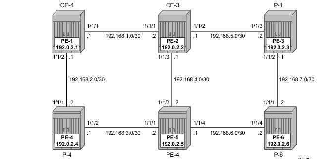
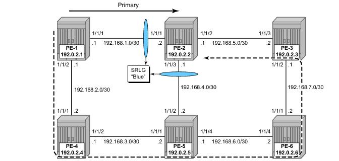
Figure 176 displays the initial topography for this section.
A:PE-1# configure router ecmp 2
A:PE-1#
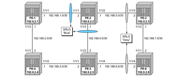
A:PE-2# /configure router mpls srlg-group blue value 1
*A:PE-2# /configure router mpls srlg-group grey value 2
*A:PE-1>config>router>mpls# info
----------------------------------------------
admin-group "green" 1
admin-group "red" 2
srlg-group "blue" value 1
srlg-group "grey" value 2
interface "system"
exit
interface "int-PE-1-PE-2"
admin-group "green"
exit
interface "int-PE-1-PE-4"
admin-group "red"
exit
*A:PE-1>config>router>mpls# interface "int-PE-1-PE-2"
*A:PE-1>config>router>mpls>if# srlg-group blue
*A:PE-2>config>router>mpls# info
----------------------------------------------
admin-group "green" 1
admin-group "red" 2
srlg-group "blue" value 1
srlg-group "grey" value 2
interface "system"
exit
interface "int-PE-2-PE-1"
admin-group "green"
srlg-group "blue"
exit
interface "int-PE-2-PE-3"
admin-group "green"
srlg-group "grey"
exit
interface "int-PE-2-PE-5"
srlg-group "blue"
exit
no shutdown
----------------------------------------------
A:PE-2>config>router>mpls#
A:PE-2# show router mpls srlg-group
===============================================================================
MPLS Srlg Groups
===============================================================================
Group Name Group Value Interfaces
-------------------------------------------------------------------------------
blue 1 int-PE-2-PE-1
int-PE-2-PE-5
grey 2 int-PE-2-PE-3
-------------------------------------------------------------------------------
No. of Groups: 2
===============================================================================
A:PE-2#
A:PE-2# show router mpls interface
==============================================================================
MPLS Interfaces
==============================================================================
Interface Port-id Adm Opr TE-metric
------------------------------------------------------------------------------
system system Up Up None
Admin Groups None
int-PE-2-PE-1 1/1/1 Up Up None
Admin Groups green
Srlg Groups blue
int-PE-2-PE-3 1/1/2 Up Up None
Admin Groups green
Srlg Groups grey
int-PE-2-PE-5 1/1/3 Up Up None
Admin Groups None
Srlg Groups blue
------------------------------------------------------------------------------
Interfaces : 4
==============================================================================
A:PE-2#
A:PE-1# show router isis database PE-2.00-00 detail
===============================================================================
ISIS Database
===============================================================================
Displaying Level 1 database
-------------------------------------------------------------------------------
LSP ID : PE-2.00-00 Level : L1
Sequence : 0x17 Checksum : 0xcc3b Lifetime : 732
Version : 1 Pkt Type : 18 Pkt Ver : 1
Attributes: L1L2 Max Area : 3
SysID Len : 6 Used Len : 508 Alloc Len : 508
TLVs :
TE SRLGs :
SRLGs : PE-1.00
Lcl Addr : 192.168.1.2
Rem Addr : 192.168.1.1
Num SRLGs : 1
1
TE SRLGs :
SRLGs : PE-3.00
Lcl Addr : 192.168.5.1
Rem Addr : 192.168.5.2
Num SRLGs : 1
2
TE SRLGs :
SRLGs : PE-5.00
Lcl Addr : 192.168.4.1
Rem Addr : 192.168.4.2
Num SRLGs : 1
1
===============================================================================
A:PE-1#
An on-line verification can be done by a tools perform CLI command. This will trigger a real CSPF call to the IGP TE database, and the result will be an ERO object which can potentially be used to set-up a CSPF based LSP.
*A:PE-1# tools perform router mpls cspf
- cspf to <ip-addr> [from <ip-addr>] [bandwidth <bandwidth>] [include-bitmap
<bitmap>] [exclude-bitmap <bitmap>] [hop-limit <limit>] [exclude-address
<excl-addr> [<excl-addr>...(upto 8 max)]] [use-te-metric] [strict-srlg]
[srlg-group <grp-id>...(upto 8 max)] [exclude-node <excl-node-id>
[<excl-node-id>..(upto 8 max)]] [skip-interface <interface-name>]
[ds-class-type <class-type>] [cspf-reqtype <req-type>] [least-fill-min-thd
<thd>] [setup-priority <val>] [hold-priority <val>]
<ip-addr> : a.b.c.d
<bandwidth> : [1..100000] in Mbps
<bitmap> : [0..4294967295] - accepted in decimal, hex(0x) or
binary(0b)
<limit> : [1..255]
<excl-addr> : a.b.c.d (outbound interface)
<use-te-metric> : keyword
<strict-srlg> : keyword
<grp-id> : [0..4294967295]
<excl-node-id> : [a.b.c.d]
<interface-name> : [max 32 chars]
<class-type> : [0..7]
<req-type> : all|random|least-fill : keywords
<thd> : [1..100]
<priority> : [0..7]
*A:PE-1#
|
•
|
to — Defines the far-end address of the LSP. This is the system-address of the destination LER
|
|
•
|
srlg-group — Specifies which SRLG groups should be avoided while building the path to the destination (ERO object)
|
|
•
|
strict-srlg — Indicates whether the SRLG group is a strict requirement or not. When this parameter is given, only paths without traversing the SRLG will be displayed.
|
*A:PE-1# tools perform router mpls cspf to 192.0.2.3
Req CSPF for all ECMP paths
from: this node to: 192.0.2.3 w/(no Diffserv) class: 0 , setup Priority 7, Hold Priority 0 TE Class: 7
CSPF Path
To : 192.0.2.3
Path 1 : (cost 20)
Start: 192.0.2.1
Egr: 192.168.1.1 -> Ingr: 192.168.1.2 (met 10)
Egr: 192.168.5.1 -> Ingr: 192.168.5.2 (met 10)
End: 192.0.2.3
*A:PE-1#
Given a restriction on srlg-group blue (grp-id =1), the result is as follows.
*A:PE-1# tools perform router mpls cspf to 192.0.2.3 srlg-group 1
Req CSPF for all ECMP paths
from: this node to: 192.0.2.3 w/(no Diffserv) class: 0 , setup Priority 7, Hold Priority 0 TE Class: 7
CSPF Path
To : 192.0.2.3
Path 1 : (cost 40)
Start: 192.0.2.1
Egr: 192.168.2.1 -> Ingr: 192.168.2.2 (met 10)
Egr: 192.168.3.1 -> Ingr: 192.168.3.2 (met 10)
Egr: 192.168.6.1 -> Ingr: 192.168.6.2 (met 10)
1 SRLGs: 2
Egr: 192.168.7.2 -> Ingr: 192.168.7.1 (met 10)
End: 192.0.2.3
*A:PE-1#
When a strict restriction is requested on srlg-group grey,
no valid CSPF path towards the destination can be found. Removing the
strict restriction results in a successful return of CSPF.
*A:PE-1# tools perform router mpls cspf to 192.0.2.3 srlg-group 2 strict-srlg
Req CSPF for all ECMP paths
from: this node to: 192.0.2.3 w/(no Diffserv) class: 0 , setup Priority 7, Hold Priority 0 TE Class: 7
MINOR: CLI No CSPF path to "192.0.2.3" with specified constraints.
*A:PE-1# tools perform router mpls cspf to 192.0.2.3 srlg-group 2
Req CSPF for all ECMP paths
from: this node to: 192.0.2.3 w/(no Diffserv) class: 0 , setup Priority 7, Hold Priority 0 TE Class: 7
CSPF Path
To : 192.0.2.3 (NOT SRLG DISJOINT)
Path 1 : (cost 20)
Start: 192.0.2.1
Egr: 192.168.1.1 -> Ingr: 192.168.1.2 (met 10)
1 SRLGs: 1
Egr: 192.168.5.1 -> Ingr: 192.168.5.2 (met 10)
1 SRLGs: 2
End: 192.0.2.3
*A:PE-1#
A:PE-1# debug router isis cspf
*A:PE-1>config>router>mpls# lsp lsp-PE-1-PE-6_FRR_facility-link
*A:PE-1>config>router>mpls>lsp# info
----------------------------------------------
to 192.0.2.3
cspf
fast-reroute facility
no node-protect
exit
primary "prim"
exit
no shutdown
----------------------------------------------
*A:PE-1>config>router>mpls>lsp#
To verify the primary path, oam lsp-trace command can be used, checking the intermediate nodes.
*A:PE-1# oam lsp-trace lsp-PE-1-PE-6_FRR_facility-link detail
lsp-trace to lsp-PE-1-PE-6_FRR_facility-link: 0 hops min, 0 hops max, 116 byte packets
1 192.0.2.2 rtt=4.32ms rc=8(DSRtrMatchLabel)
DS 1: IfAddr 192.168.5.2 MRU=1500 label=131071 proto=4(RSVP-TE)
2 192.0.2.3 rtt=11.6ms rc=3(EgressRtr)
*A:PE-1#
*A:PE-1# show router mpls lsp lsp-PE-1-PE-6_FRR_facility-link path detail
===============================================================================
MPLS LSP lsp-PE-1-PE-6_FRR_facility-link Path (Detail)
===============================================================================
Legend :
@ - Detour Available # - Detour In Use
b - Bandwidth Protected n - Node Protected
s - Soft Preemption
===============================================================================
-------------------------------------------------------------------------------
LSP lsp-PE-1-PE-6_FRR_facility-link Path prim
-------------------------------------------------------------------------------
LSP Name : lsp-PE-1-PE-6_FRR_facility-link Path LSP ID : 12288
From : 192.0.2.1 To : 192.0.2.3
Adm State : Up Oper State : Up
Path Name : prim Path Type : Primary
Path Admin : Up Path Oper : Up
OutInterface: 1/1/1 Out Label : 131071
Path Up Time: 0d 00:04:18 Path Dn Time: 0d 00:00:00
Retry Limit : 0 Retry Timer : 30 sec
RetryAttempt: 0 NextRetryIn : 0 sec
SetupPriori*: 7 Hold Priori*: 0
Bandwidth : No Reservation Oper Bw : 0 Mbps
Hop Limit : 255 Class Type : 0
Record Route: Record Record Label: Record
Oper MTU : 1496 Neg MTU : 1496
Adaptive : Enabled Oper Metric : 20
Include Grps: Exclude Grps:
None None
Path Trans : 1 CSPF Queries: 1
Failure Code: noError Failure Node: n/a
ExplicitHops:
No Hops Specified
Actual Hops :
192.168.1.1(192.0.2.1) @ Record Label : N/A
-> 192.168.1.2(192.0.2.2) @ Record Label : 131071
-> 192.168.5.2(192.0.2.3) Record Label : 131071
ComputedHops:
192.168.1.1 -> 192.168.1.2 -> 192.168.5.2
ResigEligib*: False
LastResignal: n/a CSPF Metric : 20
===============================================================================
* indicates that the corresponding row element may have been truncated.
*A:PE-1#
*A:PE-1# show router mpls bypass-tunnel detail
===============================================================================
MPLS Bypass Tunnels (Detail)
===============================================================================
-------------------------------------------------------------------------------
bypass-link192.168.1.2
-------------------------------------------------------------------------------
To : 192.168.4.1 State : Up
Out I/F : 1/1/2 Out Label : 131071
Up Time : 0d 00:06:34 Active Time : n/a
Reserved BW : 0 Kbps Protected LSP Count : 1
Type : Dynamic
SetupPriority : 7 Hold Priority : 0
Class Type : 0
Actual Hops :
192.168.2.1 -> 192.168.2.2 -> 192.168.3.2 -> 192.168.4.1
===============================================================================
*A:PE-1#
*A:PE-1>config>router>mpls# info
----------------------------------------------
admin-group "green" 1
admin-group "red" 2
srlg-group "blue" value 1
srlg-group "grey" value 2
srlg-group "red" value 3
interface "system"
exit
*A:PE-1>config>router>mpls# srlg-
srlg-database srlg-frr srlg-group
*A:PE-1>config>router>mpls# srlg-frr
- no srlg-frr
- srlg-frr [strict]
<strict> : keyword
*A:PE-1>config>router>mpls# srlg-frr strict
*A:PE-1>config>router>mpls# info
----------------------------------------------
admin-group "green" 1
admin-group "red" 2
srlg-frr strict
srlg-group "blue" value 1
srlg-group "grey" value 2
srlg-group "red" value 3
interface "system"
exit
*A:PE-1>config>router>mpls#
The option strict should only be taken if the logical topology allows this. In other words, one must be sure that an alternative path is possible which avoids SRLG-groups.
*A:PE-1# tools perform router mpls resignal lsp lsp-PE-1-PE-6_FRR_facility-link path prim
*A:PE-1#
*A:PE-1# show router mpls bypass-tunnel detail
===============================================================================
MPLS Bypass Tunnels (Detail)
===============================================================================
-------------------------------------------------------------------------------
bypass-link192.168.1.2
-------------------------------------------------------------------------------
To : 192.168.5.1 State : Up
Out I/F : 1/1/2 Out Label : 131071
Up Time : 0d 00:06:53 Active Time : n/a
Reserved BW : 0 Kbps Protected LSP Count : 1
Type : Dynamic
SetupPriority : 7 Hold Priority : 0
Class Type : 0
Actual Hops :
192.168.2.1 -> 192.168.2.2 -> 192.168.3.2 -> 192.168.6.2
-> 192.168.7.1 -> 192.168.5.1
===============================================================================
*A:PE-1#
*A:PE-1# configure router mpls lsp "lsp-PE-1-PE-2-srlg"
*A:PE-1>config>router>mpls>lsp# info
----------------------------------------------
to 192.0.2.2
cspf
primary "prim"
exit
secondary "secon"
standby
srlg
exit
no shutdown
----------------------------------------------
*A:PE-1>config>router>mpls>lsp#
To verify the datapath, the detailed output of the show router mpls command can be used, as well as the
lsp-trace OAM command. This output shows both ERO objects of the primary and secondary path.
*A:PE-1# show router mpls lsp "lsp-PE-1-PE-2-srlg" path detail
===============================================================================
MPLS LSP lsp-PE-1-PE-2-srlg Path (Detail)
===============================================================================
Legend :
@ - Detour Available # - Detour In Use
b - Bandwidth Protected n - Node Protected
s - Soft Preemption
===============================================================================
-------------------------------------------------------------------------------
LSP lsp-PE-1-PE-2-srlg Path prim
-------------------------------------------------------------------------------
Actual Hops :
192.168.1.1(192.0.2.1) Record Label : N/A
-> 192.168.1.2(192.0.2.2) Record Label : 131066
ComputedHops:
192.168.1.1 -> 192.168.1.2
-------------------------------------------------------------------------------
LSP lsp-PE-1-PE-2-srlg Path secon
-------------------------------------------------------------------------------
Actual Hops :
192.168.2.1(192.0.2.1) Record Label : N/A
-> 192.168.2.2(192.168.2.4) Record Label : 131070
-> 192.168.3.2(192.0.2.5) Record Label : 131069
-> 192.168.6.2(192.0.2.6) Record Label : 131070
-> 192.168.7.1(192.0.2.3) Record Label : 131069
-> 192.168.5.1(192.0.2.2) Record Label : 131069
ComputedHops:
192.168.2.1 -> 192.168.2.2 -> 192.168.3.2 -> 192.168.6.2
-> 192.168.7.1 -> 192.168.5.1
Srlg : Enabled
SrlgDisjoint: True
ResigEligib*: False
LastResignal: n/a CSPF Metric : 50
===============================================================================
* indicates that the corresponding row element may have been truncated.
*A:PE-1#
The lsp-trace command can be used for secondary path as well. The intermediate LSRs and the MPLS labels used can be clearly seen.
*A:PE-1# oam lsp-trace lsp-PE-1-PE-2-srlg path secon detail
lsp-trace to lsp-PE-1-PE-2-srlg: 0 hops min, 0 hops max, 116 byte packets
1 192.168.2.4 rtt=1.33ms rc=8(DSRtrMatchLabel)
DS 1: IfAddr 192.168.3.2 MRU=1500 label=131069 proto=4(RSVP-TE)
2 192.0.2.5 rtt=1.78ms rc=8(DSRtrMatchLabel)
DS 1: IfAddr 192.168.6.2 MRU=1500 label=131070 proto=4(RSVP-TE)
3 192.0.2.6 rtt=2.46ms rc=8(DSRtrMatchLabel)
DS 1: IfAddr 192.168.7.1 MRU=1500 label=131069 proto=4(RSVP-TE)
4 192.0.2.3 rtt=2.60ms rc=8(DSRtrMatchLabel)
DS 1: IfAddr 192.168.5.1 MRU=1500 label=131069 proto=4(RSVP-TE)
5 192.0.2.2 rtt=2.60ms rc=3(EgressRtr)
*A:PE-1#
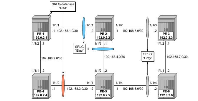
An example can be seen Figure 181 where an additional SRLG group (red) is locally on PE-1, with information related to the interface between PE-4 and PE-5.
*A:PE-1>config>router>mpls# info
----------------------------------------------
admin-group "green" 1
admin-group "red" 2
srlg-group "blue" value 1
srlg-group "grey" value 2
srlg-group "red" value 3
interface "system"
exit
interface "int-PE-1-PE-2"
admin-group "green"
srlg-group "blue"
exit
interface "int-PE-1-PE-4"
admin-group "red"
exit
srlg-database
router-id 192.0.2.4
interface 192.168.3.1 srlg-group "red"
no shutdown
exit
router-id 192.0.2.5
interface 192.168.3.2 srlg-group "red"
no shutdown
exit
exit