*A:PE-5>config>router>pim# rpfv
- no rpfv [mvpn]
- rpfv mvpn
<mvpn> : Proxy RPF vector for inter-AS rosen mvpn
mvpn enables “mvpn RPF vector” processing for Inter-AS Option B MVPN based on RFC 5496 and RFC 6513. If a “core RPF” vector is received, it will be dropped before a message is processed.
|
•
|
RFC 5384, The Protocol Independent Multicast (PIM) Join Attribute Format
|
|
•
|
RFC 5496, The Reverse Path Forwarding (RPF) Vector TLV
|
Stage 4
1: The Multicast stream threshold is reached.
configure router pim rpfv mvpn
Cisco routers need to be configured to include RD in an RPF vector using the following command for interoperability:
ip multicast vrf <name> rpf proxy rd vector
configure
router
bgp
group “iBGP"
family vpn-ipv4 mdt-safi
type internal
neighbor 192.0.2.3
next-hop-self
exit
exit
configure router bgp
enable-inter-as-vpn
group “eBGP"
family vpn-ipv4 mdt-safi
neighbor 192.168.23.1
type external
peer-as 64502
exit
exit
group “iBGP"
family vpn-ipv4 mdt-safi
neighbor 192.0.2.1
next-hop-self
type internal
exit
exit
configure router bgp
enable-inter-as-vpn
group “eBGP"
family vpn-ipv4 mdt-safi
neighbor 192.168.23.2
type external
peer-as 64501
exit
exit
group "iBGP"
family vpn-ipv4 mdt-safi
neighbor 192.0.2.5
next-hop-self
type internal
exit
exit
configure
router
bgp
group "iBGP"
family vpn-ipv4 mdt-safi
type internal
neighbor 192.0.2.2
next-hop-self
exit
exit
configure router pim
rpf-table both
apply-to non-ies
rp
static
exit
bsr-candidate
shutdown
exit
rp-candidate
shutdown
exit
exit
no shutdown
rpfv mvpn
PE-x>config>service>vprn# info
----------------------------------------------
<snip>
mvpn
auto-discovery mdt-safi
c-mcast-signaling pim
inclusive
pim ssm 239.255.0.1
exit
exit
selective
data-threshold 232.0.0.0/8 1
pim-ssm 239.255.1.0/24
exit
exit
vrf-target unicast
exit
exit
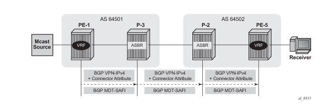
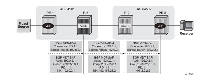
On PE-1, the debug router bgp update output shows the BGP update messages which are sent to P-3. The VPN-IPv4 update contains a connector attribute and the MDT-SAFI update is used for signaling multicast group 239.255.0.1.
"Peer 1: 192.0.2.3: UPDATE
Peer 1: 192.0.2.3 - Send BGP UPDATE:
Withdrawn Length = 0
Total Path Attr Length = 95
Flag: 0x90 Type: 14 Len: 49 Multiprotocol Reachable NLRI:
Address Family VPN_IPV4
NextHop len 12 NextHop 192.0.2.1
172.16.1.0/30 RD 1:1 Label 262142
192.0.2.1/32 RD 1:1 Label 262142
Flag: 0x40 Type: 1 Len: 1 Origin: 0
Flag: 0x40 Type: 2 Len: 0 AS Path:
Flag: 0x40 Type: 5 Len: 4 Local Preference: 100
Flag: 0xc0 Type: 16 Len: 8 Extended Community:
target:1:1
Flag: 0xc0 Type: 20 Len: 14 Connector:
RD 1:1, Egress-router 192.0.2.1
"Peer 1: 192.0.2.3: UPDATE
Peer 1: 192.0.2.3 - Send BGP UPDATE:
Withdrawn Length = 0
Total Path Attr Length = 62
Flag: 0x90 Type: 14 Len: 26 Multiprotocol Reachable NLRI:
Address Family MDT-SAFI
NextHop len 4 NextHop 192.0.2.1
[MDT-SAFI] Addr 192.0.2.1, Group 239.255.0.1, RD 1:1
Flag: 0x40 Type: 1 Len: 1 Origin: 0
Flag: 0x40 Type: 2 Len: 0 AS Path:
Flag: 0x80 Type: 4 Len: 4 MED: 0
Flag: 0x40 Type: 5 Len: 4 Local Preference: 100
Flag: 0xc0 Type: 16 Len: 8 Extended Community:
target:1:1
On P-3, the debug router bgp update output shows the BGP update messages which are sent to P-2. The VPN-IPv4 update contains an unmodified connector attribute and the MDT-SAFI update is used for signaling multicast group 239.255.0.1.
"Peer 1: 192.168.23.1: UPDATE
Peer 1: 192.168.23.1 - Send BGP UPDATE:
Withdrawn Length = 0
Total Path Attr Length = 126
Flag: 0x90 Type: 14 Len: 81 Multiprotocol Reachable NLRI:
Address Family VPN_IPV4
NextHop len 12 NextHop 192.168.23.2
192.0.2.4/32 RD 1:1 Label 262142
192.0.2.1/32 RD 1:1 Label 262142
172.16.1.0/30 RD 1:1 Label 262142
Flag: 0x40 Type: 1 Len: 1 Origin: 0
Flag: 0x40 Type: 2 Len: 6 AS Path:
Type: 2 Len: 1 < 64501 >
Flag: 0xc0 Type: 16 Len: 8 Extended Community:
target:1:1
Flag: 0xc0 Type: 20 Len: 14 Connector:
RD 1:1, Egress-router 192.0.2.1
"Peer 1: 192.168.23.1: UPDATE
Peer 1: 192.168.23.1 - Send BGP UPDATE:
Withdrawn Length = 0
Total Path Attr Length = 54
Flag: 0x90 Type: 14 Len: 26 Multiprotocol Reachable NLRI:
Address Family MDT-SAFI
NextHop len 4 NextHop 192.168.23.2
[MDT-SAFI] Addr 192.0.2.1, Group 239.255.0.1, RD 1:1
Flag: 0x40 Type: 1 Len: 1 Origin: 0
Flag: 0x40 Type: 2 Len: 6 AS Path:
Type: 2 Len: 1 < 64501 >
Flag: 0xc0 Type: 16 Len: 8 Extended Community:
target:1:1
On P-2, the debug router bgp update output shows the BGP update messages which are sent to PE-5. The VPN-IPv4 update contains an unmodified connector attribute and the MDT-SAFI update is used for signaling multicast group 239.255.0.1.
"Peer 1: 192.0.2.5: UPDATE
Peer 1: 192.0.2.5 - Send BGP UPDATE:
Withdrawn Length = 0
Total Path Attr Length = 133
Flag: 0x90 Type: 14 Len: 81 Multiprotocol Reachable NLRI:
Address Family VPN_IPV4
NextHop len 12 NextHop 192.0.2.2
192.0.2.4/32 RD 1:1 Label 262142
172.16.1.0/30 RD 1:1 Label 262142
192.0.2.1/32 RD 1:1 Label 262142
Flag: 0x40 Type: 1 Len: 1 Origin: 0
Flag: 0x40 Type: 2 Len: 6 AS Path:
Type: 2 Len: 1 < 64501 >
Flag: 0x40 Type: 5 Len: 4 Local Preference: 100
Flag: 0xc0 Type: 16 Len: 8 Extended Community:
target:1:1
Flag: 0xc0 Type: 20 Len: 14 Connector:
RD 1:1, Egress-router 192.0.2.1
"Peer 1: 192.0.2.5: UPDATE
Peer 1: 192.0.2.5 - Send BGP UPDATE:
Withdrawn Length = 0
Total Path Attr Length = 61
Flag: 0x90 Type: 14 Len: 26 Multiprotocol Reachable NLRI:
Address Family MDT-SAFI
NextHop len 4 NextHop 192.0.2.2
[MDT-SAFI] Addr 192.0.2.1, Group 239.255.0.1, RD 1:1
Flag: 0x40 Type: 1 Len: 1 Origin: 0
Flag: 0x40 Type: 2 Len: 6 AS Path:
Type: 2 Len: 1 < 64501 >
Flag: 0x40 Type: 5 Len: 4 Local Preference: 100
Flag: 0xc0 Type: 16 Len: 8 Extended Community:
target:1:1
*A:PE-5# show router bgp neighbor 192.0.2.2 received-routes mdt-safi
===============================================================================
BGP Router ID:192.0.2.5 AS:64502 Local AS:64502
===============================================================================
Legend -
Status codes : u - used, s - suppressed, h - history, d - decayed, * - valid
Origin codes : i - IGP, e - EGP, ? - incomplete, > - best, b - backup
===============================================================================
BGP MDT-SAFI Routes
===============================================================================
Flag Network LocalPref MED
Nexthop Group-Addr Label
As-Path
-------------------------------------------------------------------------------
u*>i 1:1:192.0.2.1 100 None
192.0.2.2 239.255.0.1 -
64501
*A:PE-1# show router bgp neighbor 192.0.2.4 received-routes mdt-safi
===============================================================================
BGP Router ID:192.0.2.1 AS:64501 Local AS:64501
===============================================================================
Legend -
Status codes : u - used, s - suppressed, h - history, d - decayed, * - valid
Origin codes : i - IGP, e - EGP, ? - incomplete, > - best, b - backup
===============================================================================
BGP MDT-SAFI Routes
===============================================================================
Flag Network LocalPref MED
Nexthop Group-Addr Label
As-Path
-------------------------------------------------------------------------------
u*>i 1:5:192.0.2.5 100 None
192.0.2.4 239.255.0.1 -
64502
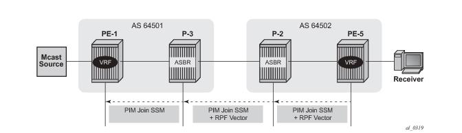
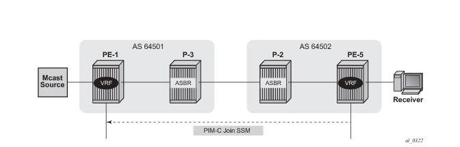
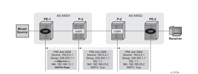
On PE-5, the debug router pim packet jp output shows the PIM join/prune message which is sent to P-2. This message contains the original source of the multicast traffic (PE-1: 192.0.2.1) and the RPF Vector (P-2: 192.0.2.2).
"PIM[Instance 1 Base]: Join/Prune
[007 14:55:54.020] PIM-TX ifId 3 ifName int-PE5-P2 -> 224.0.0.13 Length: 48
PIM Version: 2 Msg Type: Join/Prune Checksum: 0x8b5e
Upstream Nbr IP : 192.168.25.2 Resvd: 0x0, Num Groups 1, HoldTime 210
Group: 239.255.0.1/32 Num Joined Srcs: 1, Num Pruned Srcs: 0
Join Srcs:
192.0.2.1/32 Flag S <S,G> JA={rpfvMvpn 192.0.2.2 1:1}
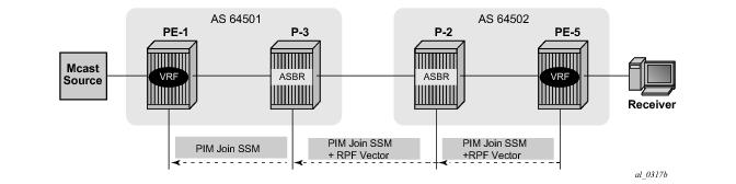
On P-2, the debug router pim packet jp output shows the PIM join/prune message which is propagated to P-3. The source of multicast traffic is untouched while the RPF Vector is modified for Inter-AS propagation.
"PIM[Instance 1 Base]: Join/Prune
[001 12:25:19.590] PIM-TX ifId 4 ifName int-P2-P3 -> 224.0.0.13 Length: 48
PIM Version: 2 Msg Type: Join/Prune Checksum: 0x835e
Upstream Nbr IP : 192.168.23.2 Resvd: 0x0, Num Groups 1, HoldTime 210
Group: 239.255.0.1/32 Num Joined Srcs: 1, Num Pruned Srcs: 0
Join Srcs:
192.0.2.1/32 Flag S <S,G> JA={rpfvMvpn 192.168.23.2 1:1}
On P-3, the debug router pim packet jp output shows the PIM join/prune message which is propagated to P-3. The source of multicast traffic is untouched while the RPF Vector is not present anymore.
"PIM[Instance 1 Base]: Join/Prune
[001 12:25:16.000] PIM-TX ifId 2 ifName int-P3-PE1 -> 224.0.0.13 Length: 34
PIM Version: 2 Msg Type: Join/Prune Checksum: 0xd694
Upstream Nbr IP : 192.168.13.1 Resvd: 0x0, Num Groups 1, HoldTime 210
Group: 239.255.0.1/32 Num Joined Srcs: 1, Num Pruned Srcs: 0
Join Srcs:
192.0.2.1/32 Flag S <S,G>
*A:PE-1#show router pim group
===============================================================================
PIM Groups ipv4
===============================================================================
Group Address Type Spt Bit Inc Intf No.Oifs
Source Address RP Inc Intf(S)
-------------------------------------------------------------------------------
239.255.0.1 (S,G) spt system 2
192.0.2.1
239.255.0.1 (S,G) spt int-PE1-P3 1
192.0.2.5
*A:PE-5# show router pim group
===============================================================================
PIM Groups ipv4
===============================================================================
Group Address Type Spt Bit Inc Intf No.Oifs
Source Address RP Inc Intf(S)
-------------------------------------------------------------------------------
239.255.0.1 (S,G) spt int-PE5-P2 1
192.0.2.1
239.255.0.1 (S,G) spt system 2
192.0.2.5
*A:PE-5# show router pim group detail
Group Address : 239.255.0.1
Source Address : 192.0.2.1
RP Address : 0
Advt Router : 192.0.2.2
Upstream RPFV Nbr : 192.168.25.2
RPFV Type : Mvpn 1:1 RPFV Proxy : 192.0.2.2
Flags : spt Type : (S,G)
MRIB Next Hop : 192.168.25.2
MRIB Src Flags : remote
Keepalive Timer Exp: 0d 00:03:00
Up Time : 0d 04:57:13 Resolved By : rtable-u
Up JP State : Joined Up JP Expiry : 0d 00:00:47
Up JP Rpt : Not Joined StarG Up JP Rpt Override : 0d 00:00:00
Register State : No Info
Reg From Anycast RP: No
Rpf Neighbor : 192.168.25.2
Incoming Intf : int-PE5-P2
Outgoing Intf List : system
Curr Fwding Rate : 5.4 kbps
Forwarded Packets : 178895 Discarded Packets : 0
Forwarded Octets : 11814210 RPF Mismatches : 0
Spt threshold : 0 kbps ECMP opt threshold : 7
Admin bandwidth : 1 kbps
A:PE-1# show router pim group detail
Group Address : 239.255.0.1
Source Address : 192.0.2.1
RP Address : 0
Advt Router : 192.0.2.1
Flags : spt Type : (S,G)
MRIB Next Hop :
MRIB Src Flags : self
Keepalive Timer Exp: 0d 00:03:30
Up Time : 0d 23:02:04 Resolved By : rtable-m
Up JP State : Joined Up JP Expiry : 0d 00:00:56
Up JP Rpt : Not Joined StarG Up JP Rpt Override : 0d 00:00:00
Register State : No Info
Reg From Anycast RP: No
Rpf Neighbor :
Incoming Intf : system
Outgoing Intf List : system, int-PE1-P3
Curr Fwding Rate : 3.4 kbps
Forwarded Packets : 826316 Discarded Packets : 0
Forwarded Octets : 34805244 RPF Mismatches : 0
Spt threshold : 0 kbps ECMP opt threshold : 7
Admin bandwidth : 1 kbps
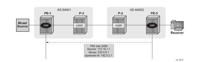
On PE-5, the debug router 1 pim packet jp output shows the PIM join/prune message which is sent to PE-1 using PMSI interface “1-mt-239.255.0.1” inside VPRN 1. All of this information and more can be found in the output of the
debug command.
49 2013/05/02 11:23:32.11 UTC MINOR: DEBUG #2001 vprn1 PIM[Instance 9 vprn1]
"PIM[Instance 9 vprn1]: Join/Prune
[006 04:23:58.880] PIM-TX ifId 16390 ifName 1-mt-239.255.0.1 -> 224.0.0.13 Len
gth: 34
PIM Version: 2 Msg Type: Join/Prune Checksum: 0xdbed
Upstream Nbr IP : 192.0.2.1 Resvd: 0x0, Num Groups 1, HoldTime 210
Group: 232.0.0.1/32 Num Joined Srcs: 1, Num Pruned Srcs: 0
Join Srcs:
172.16.1.1/32 Flag S <S,G>
The detailed information about the PIM-C group for a particular VPRN shows that default MDT is used to deliver traffic. For this purpose the show router 1 pim group detail command is used. Key parameters such as the correct multicast group, correct incoming/outgoing interfaces and non-zero flow rate allow this conclusion to be made.
*A:PE-1#show router 1 pim group detail
Group Address : 232.0.0.1
Source Address : 172.16.1.1
RP Address : 192.0.2.4
Advt Router : 192.0.2.4
Flags : spt Type : (S,G)
MRIB Next Hop : 172.16.1.1
MRIB Src Flags : remote
Keepalive Timer Exp: 0d 00:03:22
Up Time : 0d 06:39:09 Resolved By : rtable-u
Up JP State : Joined Up JP Expiry : 0d 00:00:50
Up JP Rpt : Not Pruned Up JP Rpt Override : 0d 00:00:00
Register State : No Info
Reg From Anycast RP: No
Rpf Neighbor : 172.16.1.1
Incoming Intf : int-source
Outgoing Intf List : 1-mt-239.255.0.1
Curr Fwding Rate : 3.5 kbps
Forwarded Packets : 239467 Discarded Packets : 0
Forwarded Octets : 10057614 RPF Mismatches : 0
Spt threshold : 0 kbps ECMP opt threshold : 7
Admin bandwidth : 1 kbps
*A:PE-5 show router 1 pim group detail
Group Address : 232.0.0.1
Source Address : 172.16.1.1
RP Address : 192.0.2.4
Advt Router : 192.0.2.2
Flags : spt Type : (S,G)
MRIB Next Hop : 192.0.2.1
MRIB Src Flags : remote
Keepalive Timer Exp: 0d 00:02:24
Up Time : 0d 00:01:10 Resolved By : rtable-u
Up JP State : Joined Up JP Expiry : 0d 00:00:58
Up JP Rpt : Not Joined StarG Up JP Rpt Override : 0d 00:00:00
Register State : No Info
Reg From Anycast RP: No
Rpf Neighbor : 192.0.2.1
Incoming Intf : 1-mt-239.255.0.1
Outgoing Intf List : int-receiver
Curr Fwding Rate : 3.4 kbps
Forwarded Packets : 649 Discarded Packets : 0
Forwarded Octets : 27258 RPF Mismatches : 0
Spt threshold : 0 kbps ECMP opt threshold : 7
Admin bandwidth : 1 kbps
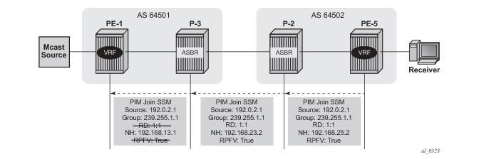
On PE-5, the debug router pim packet jp output shows the PIM join/prune message which is sent to P-2. This message contains the original source of multicast traffic (PE-1: 192.0.2.1) and the RPF Vector (P-2: 192.0.2.2). Note a new multicast group (239.255.1.1) which is signalled for purposes of the Data MDT.
"PIM[Instance 1 Base]: Join/Prune
[000 09:48:16.140] PIM-TX ifId 3 ifName int-PE5-P2 -> 224.0.0.13 Length: 48
PIM Version: 2 Msg Type: Join/Prune Checksum: 0x3aae
Upstream Nbr IP : 192.168.25.2 Resvd: 0x0, Num Groups 1, HoldTime 210
Group: 239.255.1.1/32 Num Joined Srcs: 1, Num Pruned Srcs: 0
Join Srcs:
192.0.2.1/32 Flag S <S,G> JA={rpfvMvpn 192.0.2.2 1:1}
On P-2, the debug router pim packet jp output shows the PIM join/prune message which is propagated to P-3. The source of multicast traffic is untouched while the RPF Vector is modified for Inter-AS propagation.
"PIM[Instance 1 Base]: Join/Prune
[001 22:30:36.630] PIM-TX ifId 4 ifName int-P2-P3 -> 224.0.0.13 Length: 48
PIM Version: 2 Msg Type: Join/Prune Checksum: 0x32ae
Upstream Nbr IP : 192.168.23.2 Resvd: 0x0, Num Groups 1, HoldTime 210
Group: 239.255.1.1/32 Num Joined Srcs: 1, Num Pruned Srcs: 0
Join Srcs:
192.0.2.1/32 Flag S <S,G> JA={rpfvMvpn 192.168.23.2 1:1}
On P-3, the debug router pim packet jp output shows the PIM join/prune message which is propagated to P-3. The source of multicast traffic is untouched while the RPF Vector is not present anymore.
"PIM[Instance 1 Base]: Join/Prune
[001 22:30:32.770] PIM-TX ifId 2 ifName int-P3-PE1 -> 224.0.0.13 Length: 34
PIM Version: 2 Msg Type: Join/Prune Checksum: 0x85e4
Upstream Nbr IP : 192.168.13.1 Resvd: 0x0, Num Groups 1, HoldTime 210
Group: 239.255.1.1/32 Num Joined Srcs: 1, Num Pruned Srcs: 0
Join Srcs:
192.0.2.1/32 Flag S <S,G>
*A:PE-1# show router pim group
===============================================================================
PIM Groups ipv4
===============================================================================
Group Address Type Spt Bit Inc Intf No.Oifs
Source Address RP Inc Intf(S)
-------------------------------------------------------------------------------
239.255.0.1 (S,G) spt system 2
192.0.2.1
239.255.0.1 (S,G) spt int-PE1-P3 1
192.0.2.5
239.255.1.3 (S,G) system 1
192.0.2.1
*A:PE-5# show router pim group
===============================================================================
PIM Groups ipv4
===============================================================================
Group Address Type Spt Bit Inc Intf No.Oifs
Source Address RP Inc Intf(S)
-------------------------------------------------------------------------------
239.255.0.1 (S,G) spt int-PE5-P2 1
192.0.2.1
239.255.0.1 (S,G) spt system 2
192.0.2.5
239.255.1.3 (S,G) int-PE5-P2 1
192.0.2.1
*A:PE-5#show router 1 pim group detail
===============================================================================
PIM Source Group ipv4
===============================================================================
Group Address : 232.0.0.1
Source Address : 172.16.1.1
RP Address : 192.0.2.4
Advt Router : 192.0.2.2
Flags : spt Type : (S,G)
MRIB Next Hop : 192.0.2.1
MRIB Src Flags : remote
Keepalive Timer Exp: 0d 00:01:10
Up Time : 0d 00:30:21 Resolved By : rtable-u
Up JP State : Joined Up JP Expiry : 0d 00:00:40
Up JP Rpt : Not Joined StarG Up JP Rpt Override : 0d 00:00:00
Register State : No Info
Reg From Anycast RP: No
Rpf Neighbor : 192.0.2.1
Incoming Intf : 1-mt-239.255.0.1
Incoming SPMSI Intf: 1-mt-239.255.0.1*
Outgoing Intf List : int-receiver
Curr Fwding Rate : 3.4 kbps
Forwarded Packets : 18187 Discarded Packets : 0
Forwarded Octets : 763854 RPF Mismatches : 0
Spt threshold : 0 kbps ECMP opt threshold : 7
Admin bandwidth : 1 kbps
The show router 1 pim s-pmsi detail command can also be used to verify existence of the S-PMSI instance for the VPRN 1. The output is short, but very informative: the multicast group inside VPRN, multicast source IP, multicast group which is used for S-PMSI tunneling and current flow rate can be found.
*A:PE-5#show router 1 pim s-pmsi detail
===============================================================================
PIM Selective provider tunnels
===============================================================================
Md Source Address : 192.0.2.1 Md Group Address : 239.255.1.1
Number of VPN SGs : 1 Uptime : 0d 00:29:57
MT IfIndex : 24580 Egress Fwding Rate : 3.4 kbps
VPN Group Address : 232.0.0.1 VPN Source Address : 172.16.1.1
State : RX Joined
Expiry Timer : 0d 00:02:23