For feedback and comments:
documentation.feedback@alcatel-lucent.com

Table of Contents Previous Next Index PDF


QoS Architecture and Basic Operation
In This Chapter
This section provides information about QoS architecture and basic operation.
Topics in this section include:
Applicability
The information in this section is applicable to all of the Alcatel-Lucent 7x50 platforms and is focused on the FP2 chipset, which is used in the IOM3-XP/IMM and in the 7750 SR-c12/4. The configuration was tested on release 9.0R3.
Overview
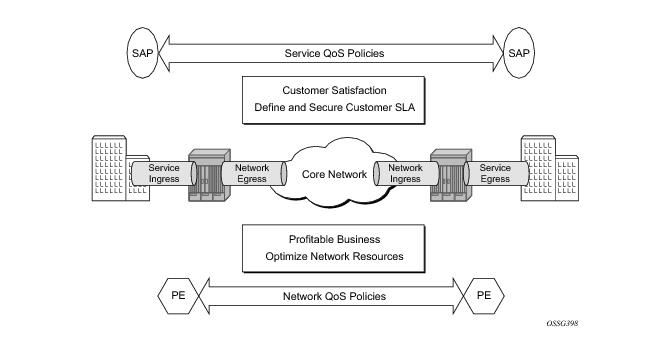
The 7x50 platforms provide an extensive Quality of Service (QoS) capability for service provider solutions. QoS is a system behavior to treat different traffic with different amounts of resources, including buffer memory and queue serving time.
By allocating system resources with certain degrees of guarantee, the bandwidth can be used more efficiently and more controllably. Lack of buffer memory leads to packet drop, while a smaller amount of queue serving time normally means longer delay for the packet and may cause buffer memory to be completely consumed and eventually also lead to packet drop.
In a single box system, such as the 7x50 platforms, different types of traffic contend for the same resources at several major points, such as the ingress to the switch fabric and the egress out of a physical port. In a multi-node network, QoS is achieved on hop by hop basis. Thus, QoS needs to be configured individually but with the consistency across the whole network.
This note is focused on the configuration of the basic QoS, namely the use of queues to shape traffic at the ingress and egress of the system. More sophisticated aspects will be referenced where appropriate but their details are beyond the scope of this note. Other topics not included are Hierarchical QoS scheduling, egress port-scheduler, queue-groups, named buffer pools, WRED-per-queue, LAGs, high scale MDA, QoS for ATM/FR and Enhanced Subscriber Management.
 
QoS Components
QoS consists of four main components:
These are also the fundamental building blocks of the QoS implementation in the 7x50. Ingress packets, classified by various rules, belong to one of eight Forwarding Classes (FC). A FC can be viewed a set of packets which are treated in a similar manner within the system (have the same priority level and scheduling behavior). Each FC has a queue associated with it and each queue has a set of parameters controlling how buffer memory is allocated for packets; if a packet is enqueued (placed on the queue) a scheduler will control the way the packet gets dequeued (removed from the queue) relative to other queues. When a packet exits an egress port, a remarking action can be taken to guarantee the next downstream device will properly handle the different types of traffic.
Configuration
 
Policies
QoS policies are used to control how traffic is handled at distinct points in the service delivery model within the device. There are different types of QoS policies catering to the different QoS needs at each point. QoS policies only take effect when applied to a relevant entity (Service Access Point (SAP) or network port/interface) so by default can be seen as templates with each application instantiating a new set of related resources.
The following QoS policies are discussed:
 
Access Network and Hybrid Ports
The system has two different types of interfaces: access and network.
Access interfaces (SAPs) are configured on access ports and network interfaces are configured on network ports. A third type of port is available, the hybrid port, which supports both access and network interfaces on the same port.
Hybrid ports are only supported on Ethernet ports and optionally with a single-chassis LAG. They must be configured to use VLANs (either single (dot1q encapsulation) or double (QinQ encapsulation) tagging) with each VLAN mapping to either the access or network part of the port. This allows the classification to associated incoming traffic with the correct port type and service. Note that port based traffic, such as LACP, CCM and EFM, uses a system queue on an access port but the default network queues on a hybrid port.
Customer traffic follows the path shown below:
 
[service ingress network egress]
[network ingress network egress]
[network ingress service egress]
 
The network administrator needs to make sure that QoS is configured correctly at each point using the appropriate QoS policies (Figure 256).
Figure 256: Service and Network QoS Policies
 
Service Ingress QoS Policy
The SAP ingress policies are created under the qos node of the CLI and require a unique identifier (from 1 to 65535). The default sap-ingress policy has identifier 1.
 
Classification
Services can be delineated at the SAP ingress by
The following configuration is an example of an IES service created with an IP interface on VLAN 2 of port 3/2/10 (IOM 3, MDA 2, port 10) and has SAP ingress QoS policy 10 applied.
configure service   
    ies 1 customer 1 create
        interface "int-access" create
            address 192.168.1.1/30
            sap 3/2/10:2 create
                ingress
                    qos 10 
                exit
            exit
        exit
        no shutdown
    exit
As traffic enters the port, the service can be identified by the VLAN tag (and unwanted packets dropped). The ingress service QoS policy applied to the SAP maps traffic to FCs, and thus to queues, and sets the enqueuing priority. Mapping flows to FCs is controlled by comparing each packet to the match criteria in the QoS policy. The match criteria that can be used in ingress QoS policies can be combinations of those listed in Table 13. Note that when a packet matches two criteria (802.1p priority and DSCP) it is the lowest precedence value that is used to map the packet to the FC.
 
Note: For an ingress QoS policy, either IP match criteria or MAC match criteria can be defined, not both.
It is possible to match MAC criteria on VPLS/Epipe SAPs and IP criteria on IP interface SAPs. However, it is also possible to classify on MAC criteria on an IP interface SAP and conversely to classify on IP criteria on VPLS/Epipe SAPs. When MPLS labeled traffic is received on a VPLS/Epipe SAP, it is possible to match on either of the LSP EXP bits (outer label) or the MAC criteria.
A SAP can be configured to have no VLAN tag (null encapsulated), one VLAN tag (dot1q encapsulated) or two VLAN tags (QinQ encapsulated). The configuration allows the selection of which VLAN tag to match against for the 802.1p bits, using the keyword match-qinq-dot1p with the keyword top or bottom.
The following example configuration shows match QinQ traffic with dot1p value 1 in the top VLAN tag entering the QinQ SAP in Epipe service 1 and assign it to FC af using queue 2.
 
configure qos
    sap-ingress 10 create
        queue 2 create
        exit
        fc "af" create
            queue 2
        exit
        dot1p 1 fc "af"
    exit
exit
 
configure service
    epipe 1 customer 1 create
        sap 1/1/1:100.1 create
            ingress
                qos 10
                match-qinq-dot1p top
            exit
        exit
        no shutdown
    exit
 
The classification of traffic using the default, top and bottom keyword parameters is summarized in Table 14. Note that a TopQ SAP is a QinQ SAP where only the outer (top) VLAN tag is explicitly specified (sap 1/1/1:10.* or sap 1/1/1:10.0).
 
 
The Drop Eligibility Indicator (DEI)1 bit can be used to indicate the in/out profile state of the packet, this will be covered later in the discussion on profile mode.
Note that ingress traffic with a local destination (for example, OSPF hellos) is classified by the system automatically and uses a set of dedicated system queues.
 
After the traffic has been classified, the next step is to assign it to a given FC. There are 8 pre-defined FCs within the system which are shown in Table 15 (note that the FC identifiers are keywords and do not have a fixed relationship with the associated Differentiated Services Code Points (DSCP)).
 
When a FC is configured for a classification, it must first be created in the configuration. One of the FCs can be also configured to be the default in case there is no explicit classification match and by default this FC is be.
Normally, once traffic is assigned to a FC at the ingress it remains in that FC throughout its time within the system. Re-classification of IP traffic at a SAP egress is possible, but is beyond the scope of this note.
Packets also have a state of being in-profile or out-of-profile which represents their drop precedence within the system, therefore there can be up to 8 distinct per hop behavior (PHB) classes with two drop precedences.
 
Buffering (Enqueuing)
Once a packet is assigned to a certain forwarding class, it will try to get a buffer in order to be enqueued. Whether the packet can get a buffer is determined by the instantaneous buffer utilization and several attributes of the queue (such as Maximum Burst Size (MBS), Committed Burst Size (CBS) and high-prio-only) that will be discussed in more detail later in this chapter. If a packet cannot get a buffer for whatever reason, the packet will get dropped immediately.
As traffic is classified at the SAP ingress it is also assigned an enqueuing priority, which can be high or low. This governs the likelihood of a packet being accepted into a buffer and so onto a queue, and is managed using the queue’s high-priority-only parameter and the buffer pools weighted random early detection (WRED) slope policies. Traffic having a high enqueuing priority has more chance of getting a buffer than traffic with low enqueuing priority. The enqueuing priority is specified with the classification using the parameter priority, and a default enqueuing priority can be configured, its default being low.
Enqueuing priority is a property of a packet and should not to be confused with scheduling priority, expedited or best-effort, which is a property of a queue.
The following configuration shows an example with all packets with dot1p value 3 are classified as ef and have their enqueuing priority set to high, all other packets are classified as af with a low enqueuing priority.
configure qos
    sap-ingress 10 create
        fc "af" create
        exit
        fc "ef" create
        exit
        dot1p 3 fc "ef" priority high
        default-fc "af"
        default-priority low 	# this is the default 
    exit
Each forwarding class is associated with at most one unicast queue. In the case of a VPLS service, each FC can also be assigned a single multipoint queue at ingress, or for more granular control, separate queues for broadcast, multicast and unknown traffic. Since each queue maintains forward/drop statistics, it allows the network operator to easily track unicast, broadcast, multicast and unknown traffic load per forwarding class. Separate multicast queues can also be assigned for IES/VPRN services which have IP multicast enabled.
This results in an Epipe SAP having up to 8 ingress queues, an IES/VPRN SAP having up to 16 ingress queues and a VPLS SAP having up to 32 ingress queues. Each queue has a locally significant (to the policy) identifier, which can be from 1 to 32.
The default SAP ingress QoS policy (id=1) has two queues; queue 1 for unicast traffic and queue 11 for multipoint traffic, and is assigned to every ingress SAP at service creation time. Equally, when a new (non-default) SAP ingress policy is created, queue 1 and queue 11 are automatically created with the default FC (BE) assigned to both. Additional queues must be created before being assigned to a FC, with multipoint queues requiring the multipoint keyword. When a SAP ingress policy is applied to a SAP, physical hardware queues on the IOM are allocated for each queue with a FC assigned (if no QoS policy is explicitly configured, the default policy is applied). Multipoint queues within the SAP ingress policy are ignored when applied to an Epipe SAP or an IES/VPRN SAP which is not configured for IP multicast.
The mechanism described here uses a separate set of queues per SAP. For cases where per-SAP queuing is not required it is possible to use port based queues, known as queue-groups, which reduces the number of queues required.
 
Scheduling (Dequeuing)
A queue has a priority which effects the relative scheduling of packets from it compared to other queues. There are two queue priorities: expedite and best-effort, with expedited being the higher. When creating a queue, one of these priorities can be configured thereby explicitly setting the queue’s priority. Alternatively the default is auto-expedite in which case the queue’s priority is governed by the FCs assigned to it, as shown in Table 15. If there is a mix of expedited and best-effort FCs assigned, the queue is deemed to be best-effort.
The following configuration displays an example that ensures that EF traffic is treated as expedited by assigning it to new unicast and multicast queues.
configure qos
    sap-ingress 10 create
        queue 3 expedite create 			
        exit
        queue 13 multipoint expedite create
        exit
        fc ef create 			   	
           queue 3 				
           multicast-queue 13 	 		
        exit
        default-fc "ef"
    exit
Once a packet gets a buffer and is queued, it will wait to be served and sent through the switch fabric to its destination port by the hardware scheduler. There are two scheduler priorities: expedited or best-effort, corresponding to the queue’s priority. The expedited hardware schedulers are used to enforce priority access to internal switch fabric destinations with expedited queues normally having a higher preference than best-effort queues. Queues of the same priority get equally serviced in round robin fashion by the associated scheduler.
When a queue gets its turn to be serviced, the scheduler will use the operational Peak Information Rate (PIR) and Committed Information Rate (CIR) attributes of the queue to determine what to do with the packet.
Out-of-profile packets have a higher probability of being dropped when there is congestion somewhere in the downstream path. Packets that are marked with out-of-profile will also be treated differently at the network egress and service egress.
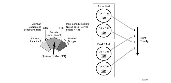
These marking actions are known as color marking (green for in-profile and yellow for out-of-profile). Using the default queue setting of priority-mode, as described above, the in/out-of-profile state of a packet is determined from the queue scheduling state (within CIR or above CIR, as described later) at the time that the packet is dequeued. An alternative queue mode is profile-mode.
 
Profile Mode
A queue is created with profile mode when the aim is that the in/out-of-profile state of packets is determined by the QoS bits of the incoming packets, this is known as color-aware (as opposed to color-unaware for priority mode).
As part of the classification, the profile state of the packets is explicitly configured. To provide granular control, it is possible to configure FC sub-classes with each having a different profile state, while inheriting the other parameters from their parent FC (for example the queue, in order to avoid out of order packets). The FC subclasses are named fc.sub-class, where sub-class is a text string up to 29 characters (though normally the words in and out are used for clarity). Any traffic classified without an explicit profile state is treated as if the queue were in priority mode.
When using the profile mode, the DEI in the Ethernet header can be used to classify a packet as in-profile (DEI=0) or out-of-profile (DEI=1).
The following configuration shows traffic with dot1p 3 is set to in-profile, dotp1p 2 to out-of-profile and the profile state of dot1p 0 depends on the scheduling state of the queue.
configure qos
    sap-ingress 20 create
        queue 2 profile-mode create
        exit                      
        fc "af" create
            queue 2
        exit
        fc "af.in" create
            profile in
        exit
        fc "af.out" create
            profile out
        exit
        dot1p 0 fc "af"
        dot1p 2 fc "af.out"
        dot1p 3 fc "af.in"
    exit
 
The difference between a queue configured in priority (default) and profile mode is summarized in Table 16 (within/above CIR is described later).
 
 
Remarking
Remarking at the service ingress is possible when using an IES or VPRN service. The DSCP/precedence field can be remarked for in-profile (in-remark) and out-of-profile (out-remark) traffic as defined above for queues in either priority mode or profile mode. If configured for other services, the remarking is ignored. If remarking is performed at the service ingress, then the traffic is not subject to any egress remarking on the same system.
The following configuration displays an example classifying traffic to 10.0.0.0/8 as FC ef in-profile and remark its DSCP to ef.
configure qos
    sap-ingress 300 create
        queue 2 profile-mode create
        exit                      
        fc “ef" create
            queue 2
            profile in
            in-remark dscp ef
        exit
        ip-criteria
            entry 10 create
                match 
                    dst-ip 10.0.0.0/8
                exit
                action fc “ef"
            exit
        exit
    exit
 
Service Egress QoS Policy
The service egress uses a SAP egress QoS policy to define how FCs map to queues and how a packet of a given FC is remarked. SAP egress policies are created in the CLI qos context and require a unique identifier (from 1 to 65535). The default SAP egress policy has identifier 1.
Once a service packet is delivered to the egress SAP, it has following attributes:
Similar to the service ingress enqueuing process, it is possible that a packet can not get a buffer and thus gets dropped. Once on an egress queue, a packet is scheduled from the queue based on priority of the queue (expedited or best-effort) and the scheduling state with respect to the CIR/PIR rates (note that the profile state of the packet [in/out] is not modified here). Egress queues do not have a priority/profile mode and have no concept of multipoint.
Only one queue exists in the default SAP egress QoS policy (id=1) and also when a new sap-egress policy is created, this being queue 1 which is used for both unicast traffic and multipoint traffic. All FCs are assigned to this queue unless otherwise explicitly configured to a different configured queue. When a SAP egress policy is applied to a SAP, physical hardware queues on the IOM are allocated for each queue with FC assigned (if no QoS policy is explicitly configured, the default policy is applied).
As mentioned earlier, re-classification of IP traffic at a SAP egress is possible.
Traffic originated by the system (known as self generated traffic) has its FC and marking configured under router/sgt-qos (for the base routing) or under service/vprn/sgt-qos (for a VPRN service). This is beyond the scope of this note.
 
Remarking
At the service egress, the dot1p/DEI can be remarked for any service per FC with separate marking for in/out-of-profile if required. The DEI bit can also be forced to a specific value (using the de-mark force command). When no dot1p/de-mark is configured, the ingress dot1p/DEI is preserved; if the ingress was un-tagged the dot1p/DEI bit is set to 0.
The following configuration shows a remark example with different FCs with different dot1p values. FC af also differentiates between in/out-of-profile and then remarks the DEI bit accordingly based on the packet’s profile.
configure qos 
    sap-egress 10 create
        queue 1 create
        rate 20000
        exit
        queue 2 create
            rate 10000 cir 5000
        exit
        queue 3 create
            rate 2000 cir 2000
        exit
        fc af create
            queue 2
            dot1p in-profile 3 out-profile 2 
            de-mark
        exit 
        fc be create
            queue 1
            dot1p 0
        exit 
        fc ef create
            queue 3
            dot1p 5
        exit 
    exit
If QinQ encapsulation is used, the default is to remark both tags in the same way. However it is also possible to remark only the top tag using the qinq-mark-top-only parameter configured under the SAP egress.
The following configuration shows a remark example with only the dot1p/DEI bits in top tag of a QinQ SAP.
configure service
    vpls 2 customer 1 create
        sap 1/1/11:2.2 create
            egress
                qos 20
                qinq-mark-top-only
            exit
        exit
    exit
For IES and VPRN services, the DSCP/precedence field can be remarked in the same way as at the service ingress, namely based on the in/out-of-profile state of the packets (and only if no ingress remarking was performed).
The following configuration shows DSCP values for FC af based on in/out-of-profile traffic.
configured qos
    sap-egress 20 create
        queue 2 create
        fc af create
            queue 2
            dscp in-profile af41 out-profile 43
        exit
    exit
 
Network Ports
The QoS policies relating to the network ports are divided into a network and a network-queue policy. The network policy covers the ingress classification into FCs and the egress remarking based on FCs, while the network-queue policy covers the queues/parameters and the FC to queue mapping. The logic behind this is that there is only one set of queues provisioned on a network port, whereas the use of these queues is configured per network IP interface. This in turn determines where the two policies can be applied. Note that network ports are used for IP routing and switching, and for GRE/MPLS tunneling.
 
Network QoS Policy
The network QoS policy has an ingress section and an egress section. It is created under the qos node of the CLI and requires a unique identifier (from 1 to 65535). The default network policy has identifier 1. Network QoS policies are applied to IP interfaces configured on a network port.
The following configuration show an example to apply different network QoS policies to two network interfaces.
configure router 
    interface "int-network-1"
        address 192.168.0.1/30
        port 1/1/11:1
        qos 28
    exit                          
    interface "int-network-2"
        address 192.168.0.5/30
        port 1/1/12
        qos 18
    exit
exit
 
Classification
The ingress section defines the classification rules for IP/MPLS packets received on a network IP interface. The rules for classifying traffic are based on the incoming QoS bits (Dot1p, DSCP, EXP [MPLS experimental bits]). The order in which classification occurs relative to these fields is:
1.
EXP (for MPLS packets) or DSCP (for IP packets)
Dot1p/DEI bit 2
2.
The configuration specifies the QoS bits to match against the incoming traffic together with the FC and profile (in/out) to be used (it is analogous to the SAP profile-mode in that the profile of the traffic is determined from the incoming traffic, rather than the CIR configured on the queue). A default-action keyword configures a default FC and profile state.
For tunneled traffic (GRE or MPLS), the match is based on the outer encapsulation header unless the keyword ler-use-dscp is configured. In this case, traffic received on the router terminating the tunnel that is to be routed to the base router or a VPRN destination is classified based on the encapsulated packet DSCP value (assuming it is an IP packet) rather than its EXP bits.
Note that Release 8.0 added the ability for an egress LER to signal an implicit-null label (numeric value 3). This informs the previous hop to send MPLS packets without an outer label and so is known as penultimate hop popping (PHP). This can result in MPLS traffic being received at the termination of an LSP without any MPLS labels. In general, this would only be the case for IP encapsulated traffic, in which case the egress LER would need to classify the incoming traffic using IP criteria.
 
Remarking
The egress section of the network policy defines the remarking of the egress packets, there is no remarking possible at the network ingress. The egress remarking is configured per FC and can set the related dot1p/DEI (explicitly or dependant on in/out-of-profile), DSCP (dependent on in/out-of-profile) and EXP (dependent on in/out-of-profile).
The traffic exiting a network port is either tunneled (in GRE or MPLS) or IP routed.
For tunneled traffic exiting a network port, the remarking3 applies to the DSCP/EXP bits in any tunnel encapsulation headers (GRE/MPLS) pushed4 onto the packet by this system, together with the associated dot1p/DEI bits if the traffic has an outer VLAN tag. Note that for MPLS tunnels, the EXP bits in the entire label stack are remarked.
For VPLS/Epipe services there is no additional remarking possible. However, for IES/VPRN/base-routing traffic the remarking capabilities at the network egress are different at the first network egress (egress on the system on which the traffic entered by a SAP ingress) and subsequent network egress in the network (egress on the systems on which the traffic entered through another network interface).
At the first network egress, the DSCP of the routed/tunneled IP packet can be remarked but this is dependent on two configuration settings:
The remarking keyword in the network QoS policy at the network egress. The configuration combinations are summarized in Table 17.
This is in addition to the remarking of any encapsulation headers and, as stated earlier, is not performed if the traffic was remarked at the service ingress.
For traffic exiting a subsequent network egress in the network, only the IP routed traffic can be remarked, again this is dependent on the ingress trusted state and egress remarking parameter.
There is one addition to the above to handle the marking for IP-VPN Option-B in order to remark the EXP, DSCP and dot1p/DEI bits at a network egress, this being remarking force. Without this, only the EXP and dot1p/DEI bits are remarked. Note that this does not apply to label switched path traffic switched at a label switched router.
 
 
The following configuration shows a ingress network classification for DSCP EF explicitly, with a default action for the remainder of the traffic and use the DSCP from the encapsulated IP packet if terminating a tunnel. Remark the DSCP values for FC af and ef and remark all traffic (except incoming VPRN traffic) at the egress. Apply this policy to a network interface.
 
configure qos
    network 20 create             
        ingress
            default-action fc af profile out
            ler-use-dscp
            dscp ef fc ef profile in 
        exit
        egress
            remarking
            fc af
                no dscp-in-profile
                dscp-out-profile af13
                lsp-exp-in-profile 6
                lsp-exp-out-profile 5
            exit
            fc ef
                dscp-in-profile af41
            exit
        exit
    exit
exit
configure router 
    interface "int-network-3"
        address 192.168.0.9/30
        port 1/1/3
        qos 20
    exit
The following configuration shows the trusted IES interface.
configure service
    ies 1 customer 1 create
        interface "int-access" create
            address 192.168.1.1/30
            tos-marking-state trusted
            sap 1/1/10:1 create
            exit
        exit
        no shutdown
    exit
The network QoS egress section also contains the configuration for the use of port-based queues by queue-groups which are out of scope of this note.
 
Network Queue Policy
The network queue QoS policy defines the queues and their parameters together with the FC to queue mapping. The policies are named, with the default policy having the name default and are applied under config>card>mda>network>ingress for the network ingress queues and under Ethernet: config>port>ethernet>network, POS: config>port>sonet-sdh>path>network, TDM: config>port>tdm>e3 | ds3>network for the egress.
The following configuration shows an ingress and egress network-queue policy.
configure card 1
    card-type iom3-xp
    mda 1
        mda-type m20-1gb-xp-sfp
        network
            ingress
                queue-policy "network-queue-1"
            exit
        exit
    exit
exit
 
configure port 1/1/11
    ethernet
        encap-type dot1q
        network
            queue-policy "network-queue-1"
        exit
    exit
    no shutdown
exit
There can be up to 16 queues configured in a network-queue policy, each with a queue-type of best-effort, expedite or auto-expedite. A new network-queue policy contains two queues, queue 1 for unicast traffic and queue 9 for multipoint traffic and by default all FCs are mapped to these queues. Note that there is no differentiation for broadcast, multicast and unknown traffic. If the policy is applied to the egress then any multipoint queues are ignored. As there are 8 FCs, there would be up to 8 unicast queues and 8 multipoint queues, resulting in 16 ingress queues and 8 egress queues. Normally the network queue configuration is symmetric (the same queues/FC-mapping at the ingress and egress).
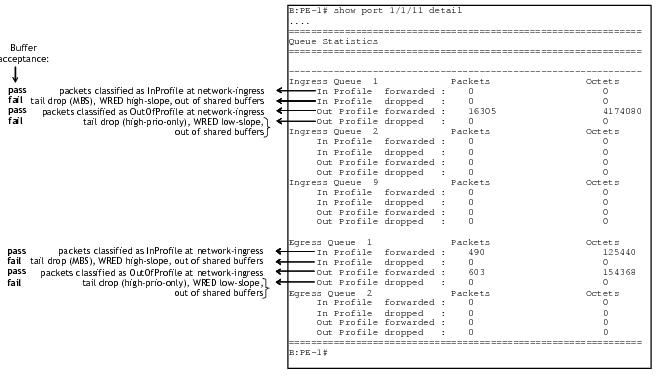
The following configuration defines a network-queue policy with FC af and ef assigned to queues 2 and 3 for unicast traffic, and queue 9 for multipoint traffic.
configure qos
    network-queue "network-queue-1" create
        queue 1 create
            mbs 50
            high-prio-only 10
        exit
        queue 2 create
        exit
        queue 3 create
        exit
        queue 9 multipoint create
            mbs 50
            high-prio-only 10
        exit
        fc af create
            multicast-queue 9
            queue 2
        exit
        fc ef create
            multicast-queue 9
            queue 3
        exit
    exit
 
Summary of Network Policies
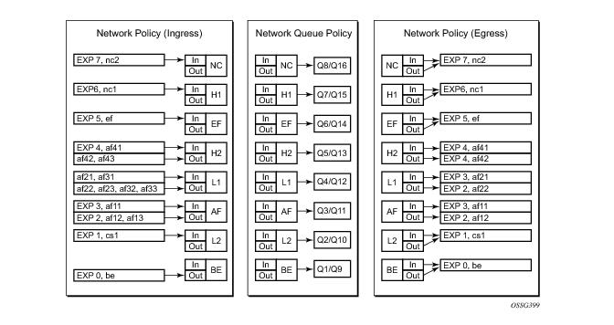
Figure 257 displays the default network policies with respect to classification, FC to queue mapping and remarking.
Figure 257: Visualization of Default Network Policies
 
Queue Management
The policies described so far define queues but not the characteristics of those queues which determine how they behave. This section describes the detailed configuration associated with these queues. There are two aspects:
 
Enqueuing Packets: Buffer Pools
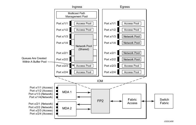
The packet buffer space is divided equally between ingress and egress. Beyond that, by default there is one pool for network ingress per FP25/IOM, with one pool per access ingress port and one pool per access/network egress port. This is shown in Figure 258. This segregation provides isolation against buffer starvation between the separate pools. An additional ingress pool exists for managed multicast traffic (the multicast path management pool) but this is beyond the scope of this note.
The buffer management can be modified using named buffer pools and/or WRED-per-queue pools which are out of scope of this note.
Figure 258: Default Buffer Pools
The size of the pools is based on the MDA type and the speed/type (access or network) of each port. Buffer space is allocated in proportion to the active bandwidth of each port, which is dependant on:
This calculation can be tuned separately for ingress and egress, without modifying the actual port speed, using the port/modify-buffer-allocation-rate. Note that changing the port’s egress-rate will also modify its buffer sizes.
 
 
The following configuration changes the relative size for the ingress/egress buffer space on port 1/1/10 to 50% of the default.
configure port 1/1/10
    modify-buffer-allocation-rate
        ing-percentage-of-rate 50
        egr-percentage-of-rate 50
    exit
Each of the buffer pools created is further divided into a section of reserved buffers and another of shared buffers, see Figure 260. The amount of reserved buffers is calculated differently for network and access pools. For network pools, the default is approximately the sum of the CBS (committed burst size) values defined for all of the queues within the pool. The reserved buffer size can also be statically configured to a percentage of the full pool size (ingress: config>card>mda>network>ingress>pool; egress: config>port>network>egress>pool). For access pools, the default reserved buffer size is 30% of the full pool size and can be set statically to an explicit value (ingress: config>port>access>ingress>pool; egress: config>port>access>egress>pool).
The following configuration sets the reserved buffer size to 50% of the egress pool space.
configure port 1/1/10
    network
        egress
            pool 
                resv-cbs 50
            exit
        exit
    exit
exit
 
configure port 1/1/11
    access
        egress
            pool 
                resv-cbs 50
            exit
        exit
    exit 
exit
Both the total buffer and the reserved buffer sizes are allocated in blocks (discrete values of Kbytes). The pool sizes can be seen using the show pools command.
It is possible to configure alarms to be triggered when the usage of the reserved buffers in the buffer pools reaches a certain percentage. Two alarm percentages are configurable, amber and red, amber-alarm-threshold <percentage> and red-alarm-threshold <percentage>. The percentage range is 1 — 1000.
The following displays a configuration for access ingress and egress pools.
configure port 1/1/1
        access
            ingress
                pool 
                    amber-alarm-threshold 25
                    red-alarm-threshold 50
                    resv-cbs 20 amber-alarm-action step 5 max 50
				exit
            exit
            egress
                pool 
                    amber-alarm-threshold 25
                    red-alarm-threshold 25
                    resv-cbs 20 amber-alarm-action step 5 max 50
                exit
            exit
        exit
 
The following is an example alarm that is triggered when the amber percentage has been exceeded and the reserved buffer size has increased from 20% to 25%:
19 2011/12/20 16:38:14.94 UTC MINOR: PORT #2050 Base Resv CBS Alarm
"Amber Alarm: CBS over Amber threshold: ObjType=port Owner=1/1/1 Type=accessEgre
ss Pool=default NamedPoolPolicy= Old ResvSize=13824 ResvSize=16128 SumOfQ ResvSi
ze=3744 Old ResvCBS=20 New ResvCBS=25"
 
When a port is configured to be a hybrid port, its buffer space is divided into an access portion and a network portion. The split by default is 50:50 but it can be configured on a per port basis.
configure port 1/1/1
    ethernet
        mode hybrid
        encap-type dot1q
    exit
    hybrid-buffer-allocation
       ing-weight access 70 network 30
       egr-weight access 70 network 30
    exit
 
 
Enqueuing Packets: Queue Sizing
Queue sizes change dynamically when packets are added to a queue faster than they are removed, without any traffic the queue depth is zero. When packets arrive for a queue there will be request for buffer memory which will result in buffers being allocated dynamically from the buffer pool that the queue belongs to.
A queue has three buffer size related attributes: MBS, CBS and high-prio-only, which affect packets only during the enqueuing process.
As with the buffer pools, the MBS, CBS and high-prio-only values attained are based on a number of discrete values (not always an increment of 3Kbytes). The values for these parameters can be seen using the show pools command.
As packets are added to a queue they will use the available CBS space, in which case they are placed in the reserved portion in the buffer pool. Once the CBS is exhausted, packets use the shared buffer pool space up to high-prio-only threshold (for out-of-profile packets) or the maximum MBS size (for in-profile packets).
The following configuration shows a queue with a specific MBS, CBS and disable high-prio-only.
configure qos
    sap-ingress 10 create
        queue 1 create
            mbs 10000
            cbs 100
            high-prio-only 0
        exit
    exit
 
Enqueuing Packets: Weight Random Earlier Detection (WRED)
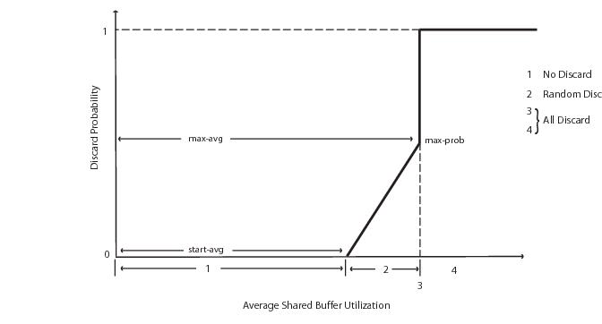
In order to gracefully manage the use of the shared portion of the buffer pool, WRED can be configured on that part of the pool, and therefore applies to all queues in the shared pool as it fills. WRED is a congestion avoidance mechanism designed for TCP traffic. This note will only focus on the configuration of WRED. WRED-per-queue is an option to have WRED apply on a per egress queue basis, but is not covered here.
WRED is configured by a slope-policy which contains two WRED slope definitions, a high-slope which applies WRED to high enqueuing priority/in-profile packets and a low-slope which applies WRED to low enqueuing priority/out-of-profile packets. Both have the standard WRED parameters: start average (start-avg), maximum average (max-avg) and maximum probability (max-prob), and can be enabled or disabled individually. The WRED slope characteristics are shown in Figure 259.
Figure 259: WRED Slope Characteristics
A time-average-factor parameter can be configured per slope-policy which determines the sensitivity of the WRED algorithm to shared buffer utilization fluctuations (the smaller the value makes the average buffer utilization more reactive to changes in the instantaneous buffer utilization). The slope-policy is applied on a network port under config>card>mda>network>ingress>pool and port>network>egress>pool and on an access port under config>port>access>ingress>pool and config>port>access>egress>pool.
WRED is usually configured for assured and best-effort service traffic with premium traffic not typically being subject to WRED as it is always given preferential treatment and should never be dropped.
The following configuration defines a WRED slope policy and apply it to an ingress access port.
configure qos
    slope-policy "slope1" create
        high-slope
            start-avg 80
            max-avg 100
            max-prob 100
            no shutdown
        exit
        low-slope
            max-avg 100
            start-avg 80
            max-prob 100
            no shutdown
        exit
        time-average-factor 12
    exit
exit
 
configure port 1/1/10
    access
        ingress
            pool 
                slope-policy "slope1"
            exit
        exit                      
    exit
exit
The queue sizing parameters and buffer pools layout is shown in Figure 260.
Figure 260: Buffer Pools and Queue Sizing
 
Dequeuing Packets: Queue Rates
A queue has two rate attributes: PIR and CIR. These affect packets only during the dequeue process.
PIR — If the instantaneous dequeue rate of a queue reaches this rate, the queue is no longer served. Excess packets will be discarded eventually when the queue reaches its MBS/high-prio-only sizes. The PIR for access ports can be set in Kb/s with a default of max or as a percentage (see below). For network ports it is set as a percentage of 390000Kb/s for ingress queues and of the port speed for egress queues, both with a default of 100%.
A percentage rate can be used in the sap-ingress and sap-egress policies, and can be defined relative to the local-limit (the parent scheduler rate) or the port-limit (the rate of the port on which the SAP is configured, including any egress-rate configured). The parameters rate and percent-rate are mutually exclusive and will overwrite each other when configured in the same policy. The example below shows a percent-rate configured as a port-limit.
config>qos#
    qos
        sap-egress 10 create
            queue 1 create
                percent-rate 50.00 cir 10.00 port-limit
            exit
 
The PIR and CIR rates are shown in Figure 261.
The queues operate at discrete rates supported by the hardware. If a configured rate does not match exactly one of the hardware rates an adaptation rule can be configured to control whether the rate is rounded up or down or set to the closest attainable value. The actual rate used can be seen under the operational PIR/CIR (O.PIR/O.CIR) in the show pools command output.
The following configuration shows a queue with a PIR, CIR and adaptation rule.
configure qos
    sap-ingress 20 create
        queue 2 create
            adaptation-rule pir max cir min
            rate 10000 cir 5000
        exit
    exit
By default, the rates apply to packet bytes based on packet accounting, which for Ethernet includes the Layer 2 frame plus the FCS. An alternative is frame accounting which adds the Ethernet inter-frame gap, preamble and start frame delimiter.
 
Dequeuing Packets: Scheduling
Once a packet is placed on a queue, it is always dequeued from the queue by a scheduler. The scheduling order of the queues dynamically changes depending on whether a queue is currently operating below or above its CIR, with expedited queues being serviced before best-effort queues. This results in a default scheduling order of (in strict priority).
1.
2.
3.
4.
This is displayed in Figure 261.
The scheduling order can be explicitly configured using hierarchical QoS (with a scheduler-policy or port-scheduler-policy) which is out of scope of this section.
Figure 261: Scheduling (Dequeuing Packets from the Queue)
The overall QoS actions at both the ingress and egress IOMs are shown in Figure 262.
 
Figure 262: IOM QoS Overview
 
Show Output
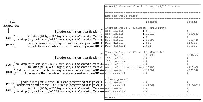
The following displays show command output for:
The show pools command output for network-ingress and network/access-egress is similar to that of access-ingress and is not included here.
 
SAP Queue Statistics
The output below shows an example of the ingress and egress statistics on a SAP for an IES service (without multicast enabled, hence no ingress multicast queue). There are two ingress queues, one being in priority mode and the other in profile mode. An explanation of the statistics is given for each entry.
 
Port Queue Statistics
This output shows an example of the ingress and egress network port statistics. There are two unicast ingress queues (1 and 2) and one multicast ingress queue (9) with two egress queues. An explanation of the statistics is given for each entry.
 
Access-Ingress Pools
This output shows an example of the default pools output for access-ingress. It includes the pools sizes, WRED information and queue parameters for each queue in the pool.
For this particular output, queue 3 on SAP 1/1/10:1 is being over-loaded which is causing its queue depth to be 6858Kbytes, made up of 5853Kbytes from the shared pool (in use) and 1008Kbytes from the reserved pool (in use). The output shows the pool total in usage as 6861Kbytes and the queue depth 3Kbytes less at 6858Kbytes, this is simply due to the dynamics of the buffer allocation which uses a ‘sliding-window’ mechanism and may therefore not always be perfectly aligned.
It can be seen that the high and low WRED slopes are both enabled and their instantaneous drop probability is shown 100% and their start/max averages are 5088Kbytes and 5856Kbytes, respectively – this shows that the reserved portion of the buffer pool on this port is exhausted causing WRED to drop the packets for this queue.
The admin and operational PIR on the overloaded queues is 10Mb/s with CIR values of zero.
B:PE-1# show pools 1/1/10 access-ingress     
===============================================================================
Pool Information
===============================================================================
Port                 : 1/1/10            
Application          : Acc-Ing           Pool Name          : default
Resv CBS             : Sum               
-------------------------------------------------------------------------------
Queue-Groups
-------------------------------------------------------------------------------
-------------------------------------------------------------------------------
Utilization                   State       Start-Avg    Max-Avg    Max-Prob
-------------------------------------------------------------------------------
High-Slope                    Up                80%       100%        100%
Low-Slope                     Up                80%       100%        100%
 
Time Avg Factor      : 12                
Pool Total           : 8448 KB           
Pool Shared          : 5856 KB           Pool Resv          : 2592 KB
 
High Slope Start Avg : 5088 KB           High slope Max Avg : 5856 KB
Low Slope Start Avg  : 5088 KB           Low slope Max Avg  : 5856 KB
                                      
Pool Total In Use    : 6861 KB           
Pool Shared In Use   : 5853 KB           Pool Resv In Use   : 1008 KB
WA Shared In Use     : 5853 KB           
 
Hi-Slope Drop Prob   : 100               Lo-Slope Drop Prob : 100
-------------------------------------------------------------------------------
Name               Tap        FC-Maps       MBS       HP-Only A.PIR    A.CIR
                                            CBS       Depth   O.PIR    O.CIR
-------------------------------------------------------------------------------
28->1/1/10:28->3
                    1/*       af            10176     0       10000    0       
                                            1008      0       10000    0       
28->1/1/10:28->1
                    1/*       be l2 l1 h2   1224      144     1000000  0       
                              h1 nc         0         0       Max      0       
28->1/1/10:28->11
                    MCast     be l2 af l1   1224      144     1000000  0       
                              h2 ef h1 nc   0         0       Max      0       
1->1/1/10:1->1
                    1/*       be l2 l1 h2   1224      144     1000000  0       
                              h1 nc         0         0       Max      0       
1->1/1/10:1->3
                    1/*       af            10176     0       10000    0       
                                            1008      6858    10000    0       
1->1/1/10:1->2
                    1/*       ef            1224      144     1000000  0       
                                            0         0       Max      0       
28->1/1/10:28->2
                    1/*       ef            1224      144     1000000  0       
                                            0         0       Max      0       
===============================================================================
B:PE-1#
Conclusion
This note has described the basic QoS functionality available on the Alcatel-Lucent 7x50 platforms, specifically focused on the FP2 chipset. This comprises of the use of queues to shape traffic at the ingress and egress of the system and the classification, buffering, scheduling and remarking of traffic on both access, network and hybrid ports.


1
IEEE 802.1ad-2005 and IEEE 802.1ah (PBB)

2
Note that network ports do not support QinQ encapsulation.

3
Strictly speaking this is marking (as opposed to remarking) as the action is adding QoS information rather than changing it.

4
A new outer encapsulation header is pushed onto traffic at each MPLS transit label switched router as part of the label swap operation.

5
The FP2 chipset is used in the IOM3-XP/IMM and in the 7750 SR-c 12/4.