System Architecture
Introduction
This section describes the architecture of the equipment and the architecture and function of the option cards.
Block diagram
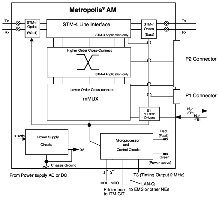
The different functions provided by the main board are (see next figure):
-
Microprocessor and control circuits.
The microprocessor and control circuits manages the different elements of the board, the interfaces (F-interface, LAN-Q) and the LEDs
-
Two STM-N (N=1 for 1643 AM; N=1 or 4 for 1643 AM) optical aggregate interfaces. One interface is referred to as the “LP1”, while the other the “LP2”.
In case of MSP protection (STM-1 only), LP1 is the “working” side and LP2 the “protection” side.
-
STM-4 Line Interface used in STM-4 applications:
-
In the transmit direction, the STM-4 Line Interface performs the collection of four AU4s and the STM-4 assembly. It performs RSOH/MSOH insertion
-
In the receive direction, the STM-4 Line Interface performs the STM-4 disassembly, the RSOH/MSOH extraction, the management of the four AU4s and the regeneration of data transmitted to the Higher Order (HO Cross-connect).
-
-
The Higher Order (HO) Cross-connect function is dedicated to STM-4 applications:
A single VC4 is accessible in add/drop mode. The three others are fully flexible cross connected to the other side.
The HO Cross-connect also performs DCC processing.
-
The Lower Order Cross-connect contains 32 E12 assemblers and disassemblers.
-
HDB3 drivers and receivers are dedicated to the sixteen 2 Mbit/s interfaces of the board.

Important! The equipment can process IT0 on the 2 Mbit/s G.703 interfaces to G.704/I.431/ETSI ETS 300 011. The bits reserved for national usage support the loop-back command (Sa6 in ETR001/I.604) and the loop signaling. It is possible to replace IT0 in both the PDH to SDH direction and in the SDH to PDH direction.
Cross-connect flexibility
The 1643 AM Cross Connect architecture consists of two cross-connects. A Lower-Order Cross Connect (LO-CC) for VC-12 and VC-3 cross-connection and a Higher Order Cross Connect (HO-CC) for VC-4 cross-connection.
High Order Cross-Connects
On STM-1 units, the HO-CC is fixed such that both the VC-4 from east and the VC-4 from west are terminated at the LO-CC.
On STM-4 units (1643 AM) the HO-CC is flexible; it allows for the cross-connection of:
-
One VC-4 (the operator can pick any) from east to the LO-CC.
-
Two VC-4s from east or two VC-4s from west or one VC-4 from east and one VC-4 from west to the STM-1 tributaries
The above mentioned flexibility offers the possibility to create add-drop rings where the lower-order signals from a VC-4 can be add-dropped, VC-4s can be add-dropped to the STM-1 tributaries and remaining VC-4s can be passed through. For VC-4 cross-connections to the STM-1 tributaries, one can apply SNC/N protection.
Lower-Order Cross-Connects
The Lower-Order Cross-Connect allows the user to cross-connect any VC-12 or VC-3 from one of the tributary ports to one of the two VC-4s that have been cross-connected to the LO-CC (see Higher-Order Cross-Connect). For VC-12 and VC-3 cross-connection one can apply SNC/N protection.
Alcatel-Lucent – Proprietary
Use pursuant to applicable agreements