Option cards
This chapter describes the option cards which can be used together with 1643 AM/1643 AMS in order to provide additional interfaces for various data rates or special applications.
X2S11TRIB/X2STM1ETRIB option card
The different functions of the X2S11TRIB (two STM-1 optical tributary line interfaces) option card are (see next figure):
-
Two STM-1 optical tributary interfaces. One interface is referred to as the “TP2.1”, while the other the “TP2.2”.
In case of MSP protection, TP2.1 is the “working” side and TP2.2 the “protection” side.
Clock and data recovery circuit separates the clock and data signals which are transmitted to ASIC circuit.
- The circuit ASIC performs :
-
In the transmit direction, the circuit ASIC performs the collect of data from the main board and the STM-1 assembly. Data are sent to the optical transmitters TP2.1 and TP2.2.
-
In the receive direction, the circuit ASIC performs the STM-1 disassembly, the management of data transmitted to the main board (HO-CC) via the P2 connector.
-
RSOH/MSOH extraction/insertion, DCC processing, VC-4 SNC/N, STM-1 MSP and switching of timing reference signal for the synchronization of the equipment.
-
-
Circuit Alarm manager performs:
X2S11TRIB option card
The X2S11TRIB option card provides two optical STM-1 short-haul tributary interfaces for an 1643 AM equipped with STM-4 line interfaces.
The X2S11TRIB option card is plugged into the P2 connector as described in Front view without cover.
The X2S11TRIB option card supports two STM-1 input and two STM-1 output signals. The physical interface is a universal optical connector which is designed for standard single mode fibers with an operating wavelength of 1310 nm.
The following figure shows the block diagram of the X2S11TRIB option card:
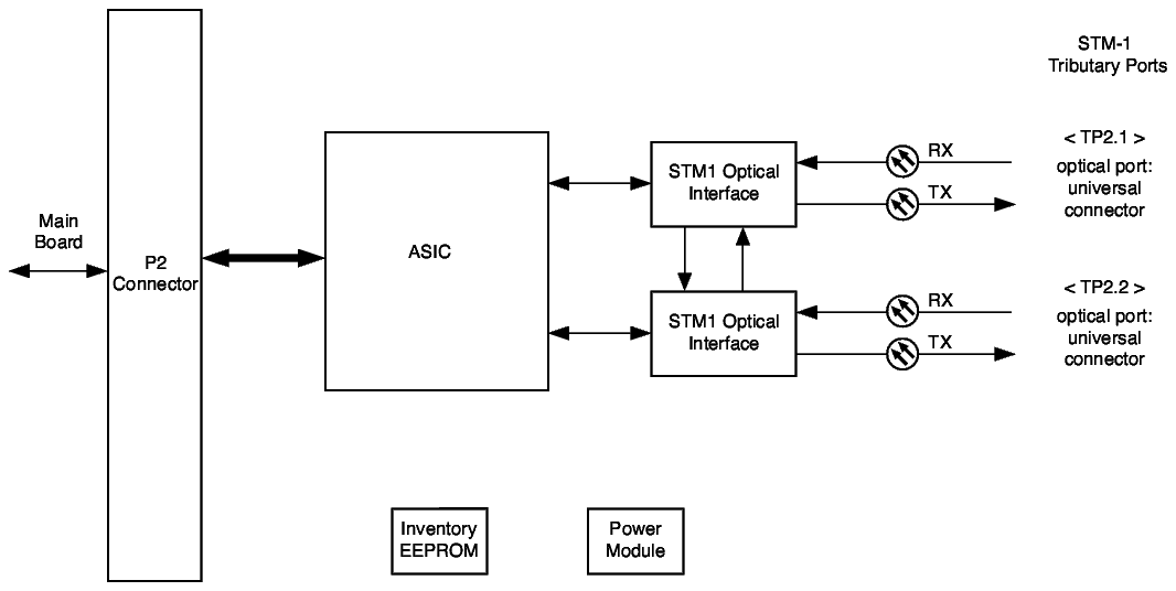
In the receive direction for both STM-1 interfaces, the optical signals are converted to electrical signals in the optical receiver. Clock and data recovery circuits separate the clock and data signals and feed them to the main ASIC. The main ASIC transmits two preprocessed STM-1 signals to the Higher Order Cross-connect on the main board via the P2 connector for further processing. The broadcast for the HO SNC/N is performed on the main board as well.
On the X2S11TRIB option card itself the following functions are performed:
Important! The power of the 1643 AM must be switched off before the option card is inserted.
Note: The STM-1 optical option cards do not utilize SFP usage.
X2STM1ETRIB option card
The X2STM1ETRIB option card provides 2 electrical STM-1 tributary interfaces for an 1643 AM equipped with STM-4 line interfaces.
The X2STM1ETRIB option card is plugged into the P2 connector as described in Front view without cover.
The X2STM1ETRIB option card supports two STM-1 input and two STM-1 output signals. The physical interface for the STM-1 signals is a coaxial 1.6/5.6 connector.
The following figure shows the block diagram of the X2STM1ETRIB option card:
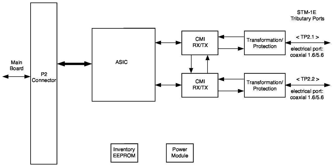
In the receive direction for both STM-1 interfaces the clock is recovered and the electrical CMI signals are decoded into the NRZ format and fed to the main ASIC. The main ASIC transmits two preprocessed STM-1 signals to the Higher Order cross-connect on the main board via the P2 connector for further processing. The broadcast for the HO SNC/N is performed on the main board as well.
On the X2STM1ETRIB option card itself the following functions are performed:
Important! The power of the 1643 AM must be switched off before the option card is inserted.
X2E3-V2 option card
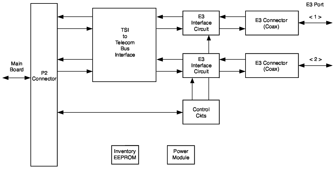
The X2E3-V2 option card provides two bidirectional 34 Mbit/s (E3) interfaces.
The X2E3-V3 option card is plugged into the P2 connector as described in Front view without cover. Physical interfaces to the additional E3 ports are four DIN1.6/5.6 coaxial connectors (one for the transmit and one for the receive directions for each E3 port).
The following figure shows the block diagram of the X2E3-V2 option board.
Important! The power of the 1643 AM/1643 AMS must be switched off before the option card is inserted.
X2DS3-V2 option card
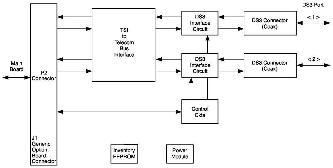
The X2DS3-V2 option card provides two additional 45 Mbit/s (DS3) interfaces.
The X2DS3-V3 option card is plugged into the P2 connector as described in Front view without cover. Physical interfaces to the additional DS3 ports are four DIN1.6/5.6 coaxial connectors (one for the transmit and one for the receive directions for each DS3 port).
The following figure shows the block diagram of the X2DS3-V2 option card.
Important! The power of the 1643 AM/1643 AMS must be switched off before the option card is inserted.
X16E1-V3 option card
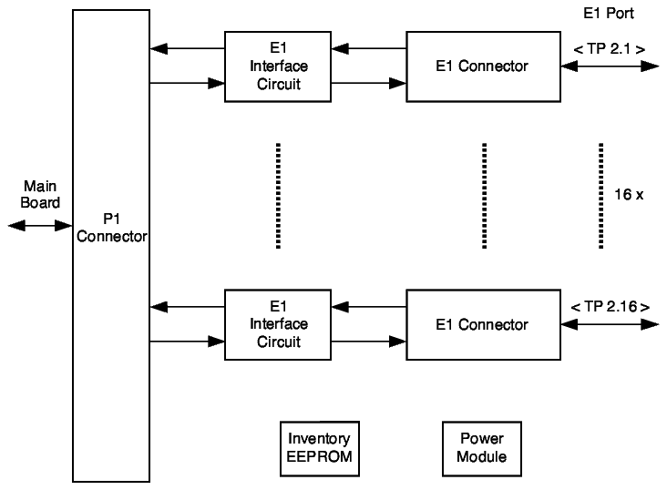
The X16E1-V3 option card provides 16 additional 2 Mbit/s (E1) interfaces.
The X16E1-V3 option card is plugged into the P1 connector as described in Front view without cover. Physical interfaces to the additional E1 ports are 16 RJ45 connectors for the use of shielded twisted pair cables.
The following figure shows the block diagram of the X16E1-V3 option card.
Important! The power of the 1643 AM/1643 AMS must be switched off before the option card is inserted.
X16DS1 option card
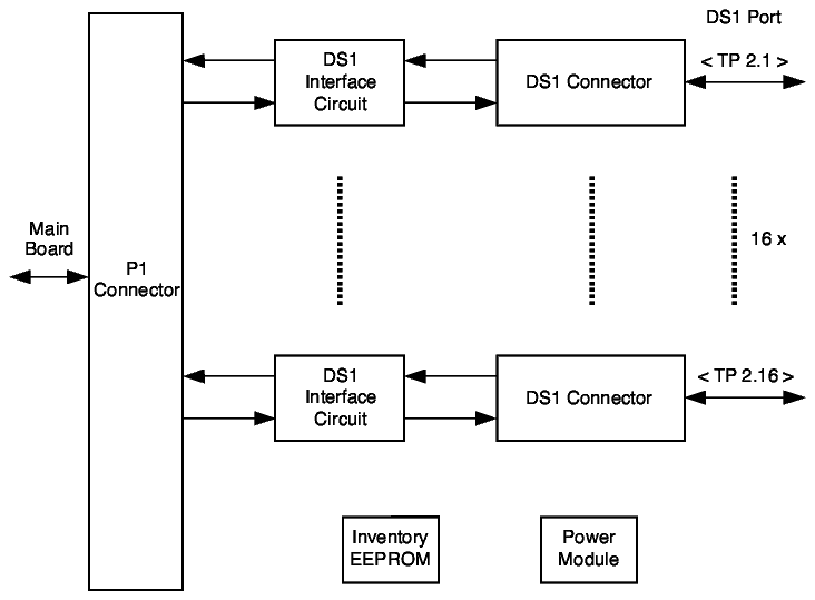
The X16DS1-V3 option card provides 16 additional 1.5 Mbit/s (DS1) interfaces.
The X16DS1-V3 option card is plugged into the P1 connector as described in Front view without cover. Physical interfaces to the additional DS1 ports are 16 RJ45 connectors for the use of shielded twisted pair cables.
The following figure shows the block diagram of the X16DS1 option card.
Important! The power of the 1643 AM/1643 AMS must be switched off before the option card is inserted.
X4X.21 option card
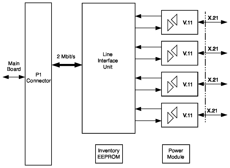
The X4X.21 option card provides four additional X.21 2 Mbit/s interfaces.
The X4X.21 option card is plugged into the P1 connector as described in Front view without cover. The physical interfaces are realized as four 15-pin female Sub-D connectors.
It provides the following features:
-
Four X.21 interfaces. The X.21 signals are bit-mapped into asynchronous 2 Mbit/s PDH signals.
-
Support of LOS defect detection and AIS insertion as consequent action
The following figure shows the block diagram of the X4X.21 option card.
Important! The power of the 1643 AM/1643 AMS must be switched off before the option card is inserted.
X8PL option card
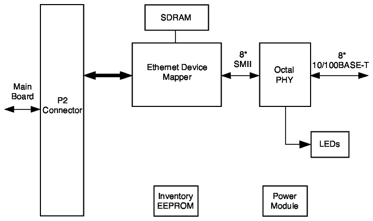
The X8PL option card provides eight Ethernet interfaces in Private Line mode for the 1643 AM/1643 AMS. The Private Line mode enables traffic to be mapped from each Ethernet port one-to-one into an SDH container. Thus a private connection from an Ethernet port through an SDH network to another Ethernet port at the remote end of the link is possible.
The X8PL option card supports a flexible allocation of SDH bandwidth to LAN ports by making use of the Link Capacity Adjustment Scheme (LCAS, see LCAS). All LAN ports have the same capabilities. Each WAN port supports VC-12-Xv (X = 1...63) or VC-3-Xv (X = 1...3).
The VC-12s that form one VCG can be chosen from any TUG-3, in any timeslot order. However, it is recommended to select the VC-12s in sequential order, preferably in one TUG-3. In this way the end-to-end network design can be kept simple and easy to maintain.
The X8PL option card supports loopbacks on outgoing Ethernet and Fast Ethernet signals.
The following figure shows the block diagram of the X8PL option card:
X4IP option card (TransLAN®)
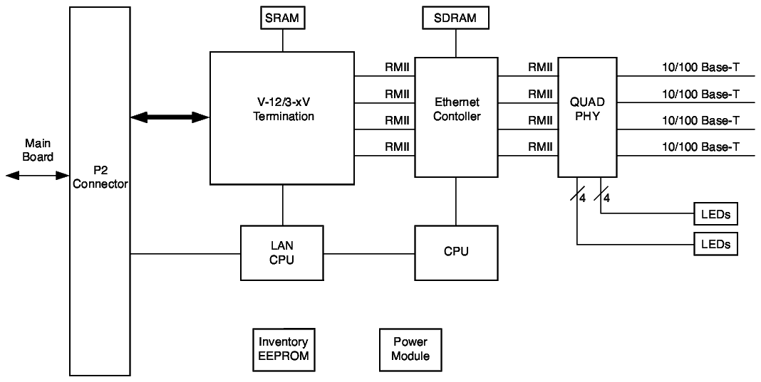
On the 1643 AM/1643 AMS an Ethernet LAN option board (X4IP) is available providing four 10/100BASE-T Ethernet interfaces. This option board is based on TransLAN®. When equipped with a TransLAN® option board, Alcatel-Lucent SDH multiplexers can offer 10/100BASE-T Ethernet interfaces.
The LAN interfaces that are supported are 10BASE-T and 100BASE-TX. The numbers "10" and "100" indicate the bit-rate of the LAN, 10 Mbit/s and 100 Mbit/s respectively. The "T" or "TX" indicates the wiring and connector type: Twisted pair wiring with RJ-45 connectors. The actual LAN speed does not need to be configured, since the Ethernet interfaces support the auto-negotiation protocol, which enables them to select the proper LAN speed automatically. The auto-negotiation function on the TransLAN® board is configurable per LAN port. This feature allows the auto-negotiation function to be manually overridden from the Alcatel-Lucent OMS or the ITM-CIT. If this auto-negotiation function is disabled, it is possible to select a specific operational mode (10 or 100BASE-T, Half/Full-Duplex).
The X4IP option card supports Enhanced Flow Classification - IEEE 802.1Q mode and IEEE 801.2ad mode. Network traffic from end users can be classified into flow categories on the edge ports of a TransLAN® domain. As a result, ports can be provisioned as “Edge” or “Interior” ports. Edge ports are either Customer Role ports (UNI) or “Virtual ports” on a Trunk port (E-NNI). A virtual port is the traffic over a trunk port belonging to a single end-user and is characterized by an S-VID tag.
On edge ports, up to seven provisionable flows can be defined with a combination of the following criteria:
Additionally, a default flow for each user is already present. When ports are designated as “Interior”, the flow classification is completely based on the S-UPT bits. There is no rate control and the S-UPT bits are transparently transported through the device. Virtual ports on a trunk port can be provisioned to behave as "Interior" ports, i.e. to use the S-UPT bits for classification instead of the freely provisionable flow. By provisioning a (virtual) port as an "Interior" port, the flow definition is fixed.
The X4IP option card supports addition of static MAC address entries into the filtering database. These entries are not submitted to the ageing time process. Conversely, users can delete MAC address entries from the filtering database using configuration commands.
The X4IP option card supports the programmable ageing pass time feature. To learn the MAC address entries automatically, the ageing pass timer can be provisioned for a duration between 10 seconds to 630 seconds in steps of 10 seconds for the whole filtering database. The default value is 300 seconds. The X4IP option card supports queries for whole and static MAC address entries and dynamic MAC address entries by specifying the MAC address and V-LAN tag.
The X4IP option card enables users to set a port in locked mode. All the new frames that are transmitted into the locked port will be dropped and the SA cannot be learnt. Alarming is reported against new frames in locked port mode.
The X4IP option card supports Committed Burst Size (CBS) and Peak Burst Size (PBS) provisioning. Users can provision the CBS and PBS parameters to QoS profiles for IEEE 802.1Q and IEEE 802.1ad modes.
The X4IP option card supports enhanced Ethernet Performance Monitoring features.
The X4IP option card supports Enhanced Basic Ethernet PM features. For detailed information, refer to Enhanced Basic Ethernet PM Counters.Note that the PM points for the 1643 AM/1643 AMS are limited.
The X4IP option card supports PM counters for high quality traffic load per TC/port. For detailed information , refer to PM counters for high quality traffic load (per TC/port).
The X4IP option card supports PM counters for low quality traffic load per TC/port. For detailed information, refer to PM counters for low quality traffic load (per TC/port).
The X4IP option card supports a performance monitoring counter for Ethernet service flow. For more information, refer to PM counters for Ethernet service flow (per flow).
The X4IP option card supports end-to-end Ethernet RTD measurement. For more information, refer to End-to-end Ethernet PM - Round Trip Delay (RTD) measurement.
The X4IP option card supports RTD PM counters and provides RTD/TCA support. For more information, refer to RTD PM Counters.
A detailed description of the Ethernet features is given in chapter Chapter 11, Ethernet Overview.
The X4IP option card supports loopbacks on outgoing Ethernet and Fast Ethernet signals.
The following figure shows the block diagram of the X4IP option card:
Alcatel-Lucent – Proprietary
Use pursuant to applicable agreements