DS1 interfaces (Main board/X16DS1 card)
Purpose
1544 kbit/s DS1 inputs and outputs can be connected to these interfaces.
Connector data
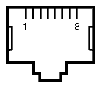
The DS1 connectors which are located on the main board (AMS only) and/or on the X16DS1 option card are RJ45 connectors with metal shell for grounding. It must be ensured that the connector metal shell has good contact with the cable shield.
Figure 4-35: DS1 connector

Table 4-12: Pin assignment (DS1 cables)
|
Point on Connector |
Signal Name |
|---|---|
|
1 |
TX positive (a-wire) |
|
2 |
TX negative (b-wire) |
|
3 |
nc |
|
4 |
RX positive (a-wire) |
|
5 |
RX negative (b-wire) |
|
6 |
nc |
|
7 |
nc |
|
8 |
nc |
Cable data
Preferably shielded twisted pair cables (CAT5) should be used (100 Ω symmetrical).
Cable connection
Please connect the DS1 cables as shown in the figure below.
Figure 4-36: DS1 cables

NOTE: The routing of the DS1 cables should be in accordance with the recommended practices of the cables selected. The cables should be strain relieved to prevent any force from being exerted on the connectors.