Link aggregation
Overview
Alcatel-Lucent 1665 DMX supports link aggregation on any two LNW170 LAN ports of the same rate (that is, 100 or 1000 Mbps), operating in switched mode. The LNW170 supports LAG operation across LNW170 packs, and equipment protected link aggregation.
LAG is also supported on the LNW910 pack. In unprotected mode, LAGs can be created from 2 FE/GE ports on the pack. In protected mode, LAGs are automatically created for ports 1–10. If required, the user can provision a LAG on port 11 (10GbE port).
Hitless bandwidth increase/decrease
Ordinarily, multiple Ethernet links between two bridges form loops (unless a spanning tree blocks all but one) so they can't be used to increase bandwidth. Link Aggregation causes defined groups of links to be treated as a single logical link, making multiple LAN ports appear as one. In this way, Bandwidth may be increased without requiring an upgrade to a higher rate link.
Facility protection
Link aggregation can also remove failed links automatically, thereby providing a means of facility protection. When a link fails, traffic is shifted to the remaining links in that Link Aggregation Group (LAG). More links than are needed can be added to the group and each is active until it fails (similar to utilizing LCAS protection for SONET tributaries). When two links are on different packs they can provide both, facility and equipment protection.
Active/Standby LAG
In Active/Standby LAG, one link of the LAG is designated as the protection link and the other is the working link. Only the working link carries MAC client traffic when none of the links fails. When the working link fails, the traffic switches to the protection link. The protection switching is bidirectional and revertive.
Equipment protection
The LNW170 and LNW910 circuit packs can be provisioned for equipment protection, in which link aggregation plays a role.
LNW170
The LNW170 supports equipment protection of function group pairs (e.g. D1, D2) using an interpack interface. Only ports 1, 2, 5 and 6 are usable. Ports 3, 4, 7 and 8 cannot be used. Signals of all usable LAN ports are fed to both LNW170 cards via the interpack interface, so that the same-numbered port of each pack belongs to a preset Link Aggregation Group. When a pair of LNW170s is used in equipment protection mode, both LNW170s are provisioned identically, except for certain physical layer parameters that remain independent. They send and receive the same signals across the backplane toward the Mains. The Mains select which of the pair is the ActiveWAN.
Link aggregation control protocol
Link Aggregation is specified in IEEE 802.3 clause 43, formerly specified in 802.3ad. An pack can be configured to either use this standard protocol to control link aggregation (which negotiates with the equipment at the other end of the link) or to simply force aggregation without a control protocol. Both ends should be provisioned to use the same protocol
General link aggregation rules
Link aggregation behaves along the following basic guidelines:
-
Maximum of 4 LAGs per pack, 2 ports per LAG, and 8 LAGs per function unit or growth group. There are 8 ports on each LNW170 pack.
-
The two ports in a LAG must be on the same pack, and be functioning at the same rate (i.e. 100 or 1000 Mbps).
-
All links in a LAG are in-service until they fail. Standby links, providing 1x1 SONET-style protection, are a future feature.
-
When a LAG is created, the attributes (VLAN, virtual switch, and other L2 provisioning) of the first port used to establish the LAG are transferred to the LAG. When the second port is added, it then inherits the L2, VLAN and Virtual Switch (VS) characteristics of the LAG for the time it remains a member. It can not be part of a VS or have any VLAN provisioning when added.
-
When a port is removed from a particular LAG, it is no longer a member of a VS.
-
A port must have L2 and VS provisioning in order for a port to be used as the Lead port or to establish a LAG (VLAN provisioning not required). This information is then transferred to the LAG once it's created.
-
The last port/member of a LAG cannot be removed from the LAG; the LAG itself must be deleted. The last port/member of a LAG inherits the LAG's L2, VLAN, and VS attributes.
-
If the last member in the LAG was the first member added originally, and if there were no subsequent changes to L2 and VLAN attributes, the port will effectively revert to its original state when the LAG is deleted.
-
If the last member/port in the LAG was not the first added initially it will inherit the characteristics of the LAG rather than reverting to its original state.
-
Link aggregation example
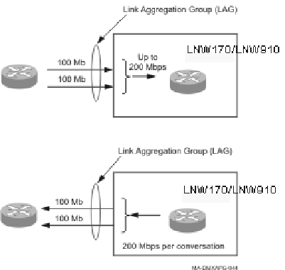
The figure below depicts link aggregation on two LNW170 LAN ports functioning at 100Mbps. The top portion of the figure shows two ports receiving separate 100 Mbps inbound flows. The bottom portion depicts the same two flows being equally split across the two outbound ports in the LAG. In this example, no failure has occurred and both ports comprising the LAG are in-service.
Traffic entering incoming ports is aggregated into a LAG. While both ports are in-service, outgoing traffic is split between working ports.
Figure 5-14: Link aggregation at 100 Mbps (all ports in-service)

The instance pictured above represents the ideal case, in which there are at least 2 flows, each a maximum of 100Mbps. In this case they can be equally split over the two ports comprising the LAG. The ability to split the two flows across multiple ports also depends on the distribution of MAC/IP addresses.
Link aggregation employs an algorithm that assigns traffic to member ports to prevent misreading. A given flow can be assigned to only one port and cannot be split across multiple ports in the same LAG. To increase flexibility, Alcatel-Lucent 1665 DMX allows a flow to be defined by either a MAC source and destination address pair or an IP source and address pair. The algorithm uses the XOR of the least significant bits of the address pairs to assign a port/link. Therefore, the actual load balancing achieved depends on the distribution of MAC/IP addresses.
Link aggregation transparency
Link aggregation allows multiple physical links between Ethernet switches to be treated as a single link. This provides for more bandwidth between the switches than can be transmitted over a single Ethernet port and it can provide protection from a cable, Ethernet port, or Ethernet circuit pack failure.
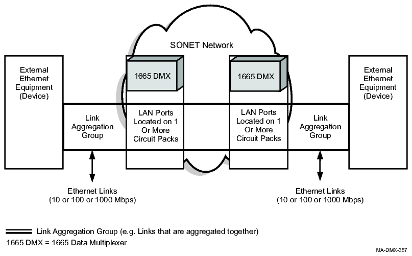
The Alcatel-Lucent 1665 DMX supports link aggregation transparency, as shown in the following figure. This allows the attached equipment to use link aggregation without participation by the Alcatel-Lucent 1665 DMX provisioning.
Figure 5-15: Link aggregation

The figure shows two Ethernet devices running link aggregation interconnected via Ethernet circuit packs and a SONET Network. The Alcatel-Lucent 1665 DMX shelves and the SONET network are invisible to the two Ethernet devices. The Ethernet traffic is transparently transferred between the external devices. Link aggregation is typically implemented using two dedicated unprotected point-to-point links (Ethernet Private Line Service) for each pair of external ports.
Link aggregation transparency requires a default VLAN ID tag or port tag in 802.1Q and Transparent Tagging mode. If a default VLAN or port tag is not specified at the port, the link aggregation messages are dropped.