ML-PPP termination
Overview
At many base transceiver stations (BTS), T1/E1 Layer-1 technology is used to transport wireless voice and data between the BTS and the servers at the Mobile Switching Center (MSC). User traffic and signaling are multiplexed onto common DS1/E1 signals and the IP layer is used to route packets for the desired MSC server.
The layer 2 protocol used for IP backhaul by the BTS URCs is Multi-Link PPP over one or more DS1/E1 signals. Each URC at the BTS uses a group of T1/E1s (typically 1–4) that is treated as a single bandwidth pipe called a Multilink Group (MLG). Traffic is bundled, fragmented, and prioritized to maximize the throughput while minimizing voice delay and jitter. Since each link requires a unique IP address, bundling of DS1/E1 signals into MLGs minimizes the number of IP addresses required by a BTS and also provides the ability to aggregate bandwidth.
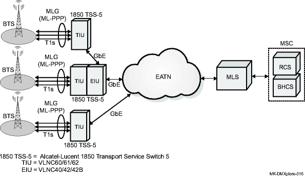
The Alcatel-Lucent 1850 TSS-5 VLNC60/61/62 ML-PPP termination feature supports the IP backhaul application by reducing the frame overhead and off-loading the MLSs. The VLNC60/61/62 terminates the ML-PPP session and transmits the IP traffic directly over the packet network using Ethernet 802.1Q encapsulation. It interworks between the DS1/E1 ML-PPP links from the BTS Universal Radio Controller (URC) and Ethernet links running 802.1Q encapsulation towards the MSCs.
For specific configuration information and CLI command information see the Alcatel-Lucent 1850 Transport Service Switch (TSS-5) Command Line Interface Guide.
ML-PPP termination architecture
Alcatel-Lucent 1850 TSS-5 supports up to 8 MLGs per VLNC60/62 and up to 16 MLGs per VLNC61. On the VLNC60/62, up to 8 T1/E1 ports can be aggregated onto a single MLG. On the VLNC61, up to 16 T1/E1 ports can be aggregated onto a single MLG. ML-PPP links within the MLGs are terminated on the VLNC60/61/62 installed in the Alcatel-Lucent 1850 TSS-5. The VLNC60/61/62 can connect directly to the EATN, or traffic from multiple shelves with VLNC60/61/62s can be aggregated through a shelf with a VLNC40/42/42B installed.

Address assignment
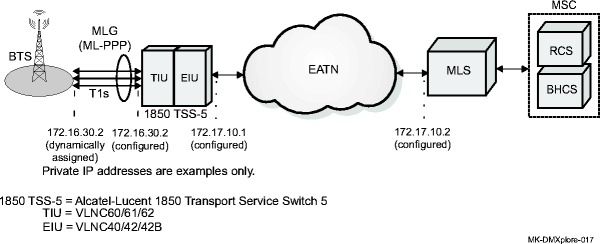
Each MLG can be configured with a single local IP address on the VLNC60/61/62. The VLNC60/61/62 will assign a remote IP address to the MLG at the BTS, based on the locally configured IP address and a user configured offset value. Remote IP address assignment is dynamically communicated using the IPCP IP Address Option during ML-PPP link initialization. VLNC60/61/62 also assigns the addresses of a pair of OA servers, known as Backhaul Connection Servers (BHCS) at the MSC to each BTS URC, via IPCP extensions RFC 1877. This is done so that BTS URC can communicate with MSC RCS, because neither has knowledge of the others address.
This takes place in the following way:
-
The BTS URC sends an address query to the RCS containing its own address.
-
The BHCS replies with the RCS address
-
The BTS can then initiate connection with RCS
Important!
There is one set of primary/backup BHCS addresses per VLNC60/61/62 for all MLGs.

Capacities
The following table describes the capacities of the VLNC60/61/62 for IP backhaul.
Table A-11: IP backhaul capacities
|
VLNC60/61/62 item |
Maximum size |
|---|---|
|
MLGs |
8 (VLNC60/62) |
|
16 (VLNC61) | |
|
DS1/E1 signals per MLG |
8 (VLNC60/62) |
|
12 (VLNC61) | |
|
Classes per MLG |
4 |
|
IP routes |
128 |
|
ARP entries |
32 |
|
L3 ACLs |
64 |
|
128 | |
|
L2 ACLs |
64 |
|
VLANs |
32 |
|
Fragment Map Profiles |
8 (VLNC60/62) |
|
16 (VLNC61) |