Internal NSP communication
Introduction
Communication among NSP components in a data center is performed over the internal network. Each internal interface is secured using TLS.
Note: TLS is also applied to the communication among internal NSP system services and processes. For additional robustness, the system-level communication uses a certificate from an internal root CA that is inaccessible to external agents.
Each NSP cluster member has a unique IP address; however, the cluster members share one virtual IP address.(VIP) that is assigned to the cluster for access by other components.
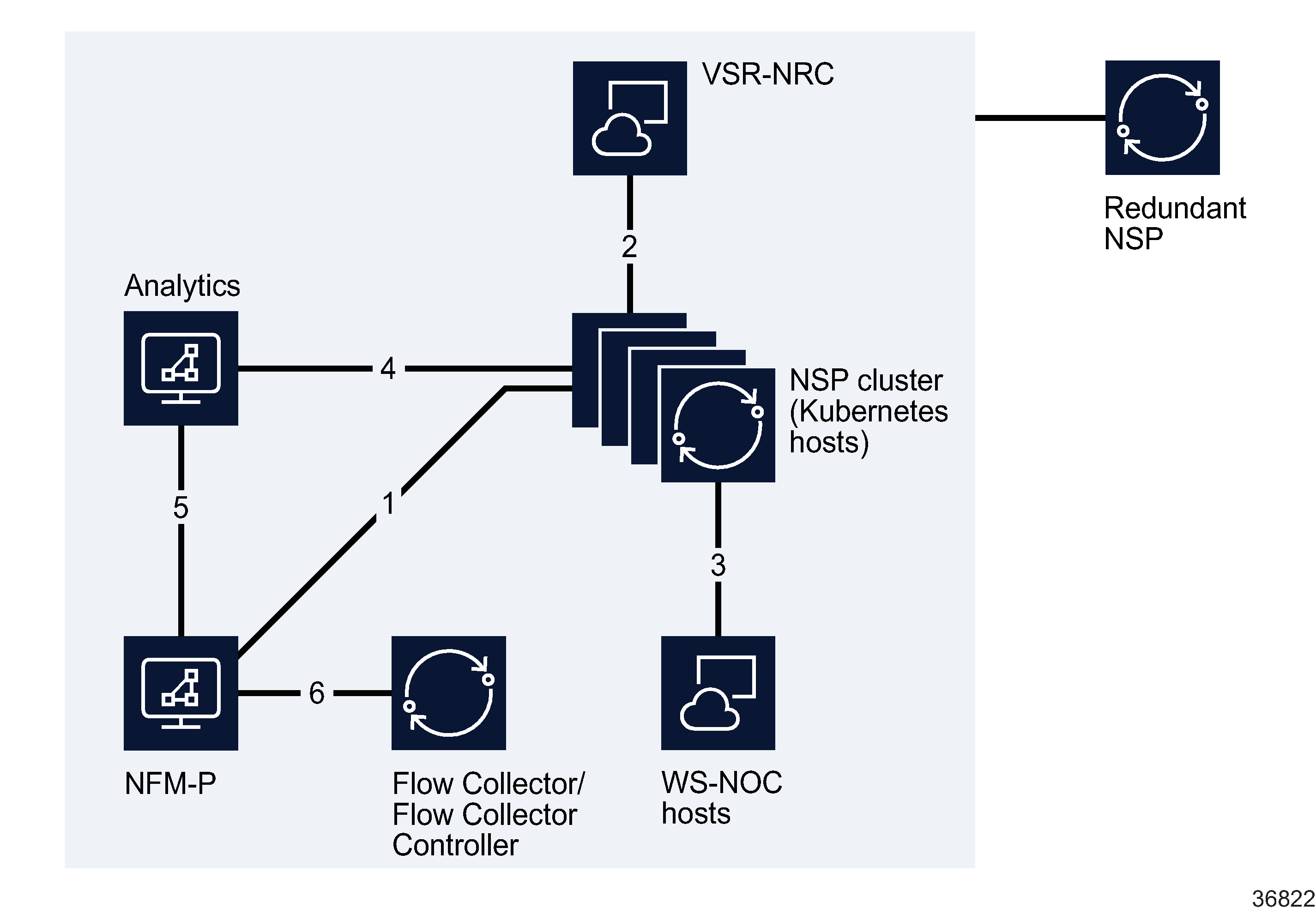
Figure 7-3: Internal NSP interfaces
The following table describes each interface shown in Figure 7-3, Internal NSP interfaces.
Table 7-3: Internal NSP connections
|
Interface |
Endpoints |
Traffic type |
|---|---|---|
|
1 |
NFM-P NSP cluster |
SSO authentication. Zookeeper registration, Kafka messaging, NFM-P API |
|
2 |
NSP cluster VSR-NRC (BOF interface) |
Data connection – CROTO (non-secure) |
|
3 |
WS-NOC NSP cluster |
SSO authentication, Zookeeper registration (non-secure), REST over HTTPS, proprietary WS-NOC HTTP communication |
|
4 |
NSP cluster Analytics hosts |
SSO authentication, Zookeeper registration, Kafka messaging, PostgreSQL transactions |
|
5 |
NFM-P Analytics hosts |
TLS-secured JDBC and REST |
|
6 |
NFM-P NSP Flow Collectors / Flow Collector Controllers |
HTTPS, JMS |
Communication between redundant data centers
NSP geographic redundancy, sometimes called geo-redundancy, uses a disaster-recovery (DR) mechanism to engage an identical NSP cluster at a standby site to support service continuity in the event that the primary site suffers an unrecoverable failure. To effectively support a DR NSP deployment, the NSP clusters at the geo-redundant sites require robust, secure communication.
The following NSP components perform DR communication over the internal NSP network:
For more information about DR deployments, see Chapter 8, System redundancy and fault tolerance.
