How do I view RAN transport equipment and bindings?
Simplified RAN Transport Equipment and Bindings Summary
You can view a summary of managed T-BTS and their associated transport bindings using the Simplified RAN Transport Equipment and Bindings Summary view in the Network Map and Health view. This view can be filtered to display all radio planes, only those associated with a transport slice, or only the “basic” functions that do not belong to a slice.
This view displays the following counters:
-
Healthy Bound radio planes (radio planes, with enabled or unknown operationalState, associated to a Transport Service via their vlanId in the same subnet)
-
Affected Bound radio planes (radio planes, with disabled operationalState, associated to a Transport Service via their vlanId in the same subnet)
-
Partially Bound radio planes (radio planes, with at least one of the transport paths “bound”, while one or more of the others are any combination of “partially bound”, “misconfigured”, and “not bound”).
-
Misconfigured radio planes (radio planes associated to a Transport Service via their vlanId but with a configuration mismatch)
-
Not Bound radio planes (radio planes configured with vlanId and transportIpAddress but with no associated Transport Service)
When the value of a counter is over 1000, the number displayed by the counter bubble is rounded down to the nearest 100 (for example, 8969 displays as “8.9k”). The mouse-over tooltip for the counter bubble displays the exact value.
Binding a radio plane to a transport service is possible only if there is a link between the BTS port and a Service Access Point (i.e a router port). The link can be a direct physical cable to the router’s port, or the two ports can be linked via a UBT-SA link (waveguide between two UBT Standalone Gears) or via MSS or other BTS nodes (via L2 backhaul services).
Fault management
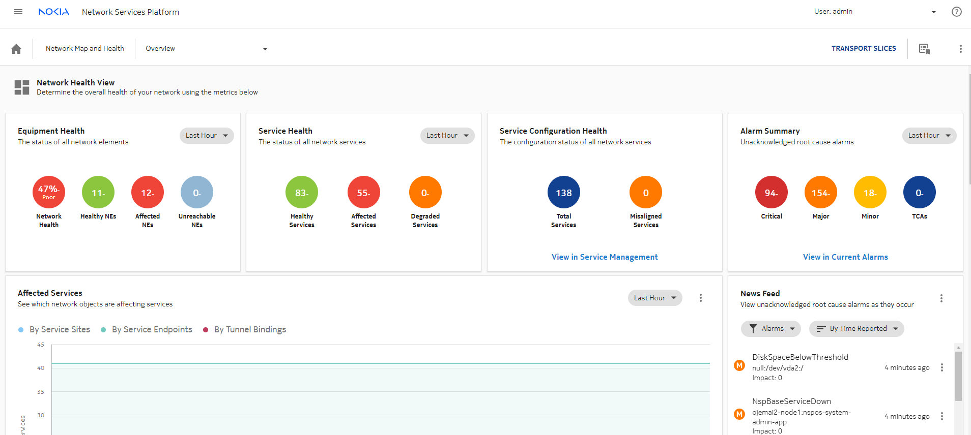
Network Map and Health, Overview displays the overall health of the network, including the health of services and an at-a-glance view of alarms. For general information about network troubleshooting using NSP, see the NSP Network and Service Assurance Guide.
Figure 3-1: Network Map and Health, Overview
T-BTS alarms are updated in real time in NSP (Alarm Views, network map views, Radio Plane Bindings table, Transport Paths Binding Summaries).
SRT maps T-BTS alarms to the relevant equipment, such as ports and cards. The alarmed object ID displays the DN of the affected BTS or equipment (port or card). After an event that affects the alarm list, such as the discovery of new T-BTS nodes, the alarm view may need to be refreshed to display the updated alarm list.
Using views and crosslaunching other NSP functions
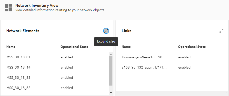
You can expand any of the Network Inventory View panels and open a NSP function view for that component type by clicking ![]() and selecting a navigation option.
and selecting a navigation option.
Figure 3-2: Expand panel size
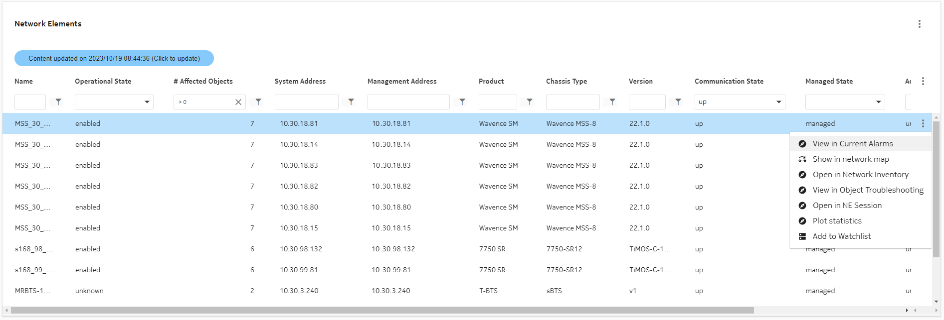
SRT offers multiple crosslaunch options to other NSP functions for a selected NE.
Figure 3-3: Navigation from Network Elements list to other NSP functions
Radio plane bindings in SRT
SRT displays radio plane information in the following panels:
The Simplified RAN Transport Equipment and Bindings Summary panel displays several KPIs represented by bubbles and can be viewed by All, Slice, or Base.
Figure 3-4: Simplified RAN Transport Equipment and Bindings Summary
Clicking the # Base Stations Stations (T-BTS) counter bubble automatically navigates to a filtered list of T-BTS Network Elements. Clicking any of the radio plane-specific counter bubbles automatically navigates to a list in the Radio Plane Bindings table that is filtered for the selected KPI. The table can be further filtered and sorted to help find specific entries.
Note: Filtering is case-sensitive and does not support the use of { }.
When automatic refresh is enabled, the bubbles and table contents are refreshed every 5 minutes.
Clicking the # Radio Planes KPI navigates to and expands the Radio Plane Bindings table.
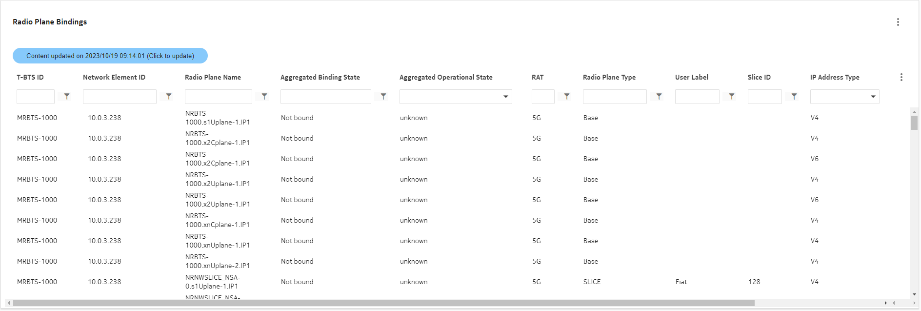
Figure 3-5: Radio Plane Bindings table
The Radio Plane Bindings table provides a filterable view of radio planes keyed on T-BTS and the NE ID, represented by the IP address of the BTS. If the table view is not expanded, click More ![]() and select Expand size to expand to the full-size displayed in
Figure 3-5, Radio Plane Bindings table.
and select Expand size to expand to the full-size displayed in
Figure 3-5, Radio Plane Bindings table.
Radio planes with multiple transport paths
Radio planes with multiple transport paths are represented in the Radio Plane Bindings table by a single entry. The “Aggregated Binding State” and “Aggregated Operational State” columns in the table display an aggregate value based on the current values of the associated transport paths. The aggregated value for Binding State can be one of the following:
-
Partially bound—at least one of the transport paths is “bound”, while one or more of the others are any combination of “partially bound”, “misconfigured”, and “not bound”.
-
Misconfigured—none of the transport paths are “bound”, and at least one path is “misconfigured”.
The aggregated value for Operational State can be one of the following:
-
Disabled—at least one transport path is operationally “Disabled”, regardless of the state of the other paths.
-
Unknown—at least one transport path is operationally “Unknown”, and none are “Disabled”. For example, one path is “Enabled” but two others are “Unknown”.
Viewing a radio plane in Object Troubleshooting
You can navigate from a radio plane in the bindings table to a specific radio plane view in Object Troubleshooting by clicking the ![]() icon. This view provides detailed information using the following panels:
icon. This view provides detailed information using the following panels:
-
Radio Plane Summary—summarizes identifying information for the radio plane, including T-BTS ID, NE ID, Radio Plane Name, RAT (Radio Access Technology), and source IP.
-
Radio Plane Health Summary—displays the aggregated Binding State and aggregated Operational State values for the radio plane.
-
Transport Binding Path Summary—displays entries for each transport path (non-aggregated) for the radio plane with the full set of associated parameter values. In this view, you can see individual paths and perform assessment based on their Binding State and color-coded alarm status. You can also navigate from an entry in this list to a Current Alarms view filtered on chosen transport path by clicking More
For a detailed view of a transport path, you can click More and selecting View in Current Alarms.
 and select View Details. This moves focus to a series of panel tables under the path summary table that display the following components involved in the transport path binding:
-
Network Element Ports—the ports that comprise the transport path and their operational states.
-
Physical Links—the name of the associated physical links and their operational states.
-
Services—services associated with the transport path, the service types (such as VPRN or VPLS), operational states, and affected component details (a list of the service components that are used by the transport path and have a disabled operational state).
From these panel tables you can further drill-down by clicking the
 icon for an entry to view the selected component in Object Troubleshooting.
 -
The following is an example workflow for using Object Troubleshooting to diagnose issues with a radio plane.
-
We open the Radio Plane Bindings table and see that a radio plane for MRBTS-308 has an Aggregated Binding State of “Bound” but an Aggregated Operational State of “disabled”. Since these are aggregated states, we need to view the associated transport paths individually. We click
 for the radio plane to view it in Object Troubleshooting.
 -
In the Object Troubleshooting view, we can see in the Transport Paths Binding Summary that all three transport paths for the radio plane are operationally disabled. We select a transport path, click More
 , and select View Details. The three panels described above (Network Element Ports, Physical Links, and Services) are displayed.
 -
In the three panels, we can enter a filter entry of “disabled” for each of them in the Operational State column. All three panels now only display components that are operationally disabled.
-
Using the filtered displays, we can see that a TRMOD in Network Element ports is disabled. Correspondingly, a physical link is also disabled. We can click
 to open Object Troubleshooting for the physical link.
 -
In the Object Troubleshooting view for the physical link, we can verify that one of the link endpoints matches the disabled TRMOD, and that this endpoint is the only one that is operationally disabled for that link.
-
Moving back to the Object Troubleshooting view for the transport path, we can also see in the Services panel that a service is operationally disabled. In the Affected Component Details column, the message states that the L2 Backhault Endpoint with the same name as the faulted TRMOD is disabled.
-
We now know that the issue with the radio plane is being caused by a faulted port on the MRBTS.
See the NSP Network and Service Assurance Guide for more information about the functionality available in Object Troubleshooting.
Radio Plane Bindings table parameters
See Appendix B, Radio Plane Bindings table parameters for more information about the parameters displayed in the Radio Plane Bindings table.
Binding State and Binding State Details
The Binding State column displays the status of each binding entry while the Binding State Details column provides a more detailed message on the status cause. The following table provides remedial action information for each possible binding state details message.
Note: A radio plane may have several binding state details, separated by commas.
Table 3-1: Binding States, details messages, and remedial actions
|
Binding State |
Possible Binding State Details |
Remedial action |
|---|---|---|
|
Not Bound |
No physical connectivity to backhaul. |
Check physical links between T-BTS and router. If physical links are OK but LLDP is not activated, create links between T-BTS and router via network map view. |
|
Not Bound |
T-BTS Port Name T-BTS port name: no L3 VPN found on Router router NE ID router port name. |
Check the L3 VPN service configuration and/or Life Cycle State in Service Management or create a L3 VPN service with this VLAN on the router/port or bind the radio plane to another L3 VPN of this router/port. |
|
Not Bound |
T-BTS Port Name T-BTS port name: no L2 Backhaul service on Node NE ID NE port name leading to a Router. |
Check the L2 backhaul service configuration and/or Life Cycle State in Service Management or create a L2 backhaul service with this VLAN between the T-BTS and the router. |
|
Misconfigured |
Vlan Id not configured for T-BTS radio plane Source IP Address ip_address. |
Bind the radio plane with the same IP address and the same VPRN/VLAN. |
|
Misconfigured |
Vlan Id is not configured on physical T-BTS Port Name T-BTS port name. |
Bind the radio plane with the same IP address and the same VPRN/VLAN. |
|
Misconfigured |
No route defined in T-BTS Routing Table. |
Add routing configuration in the MRBTS (via WEB EM or NetAct/MantaRay NM). |
|
Misconfigured |
T-BTS Transport IP Address and L3 VPN SAP IP Address are not in the same subnet. |
Bind the radio plane with the same VPRN/VLAN but correct IP address. |
Binding radio planes to transport services
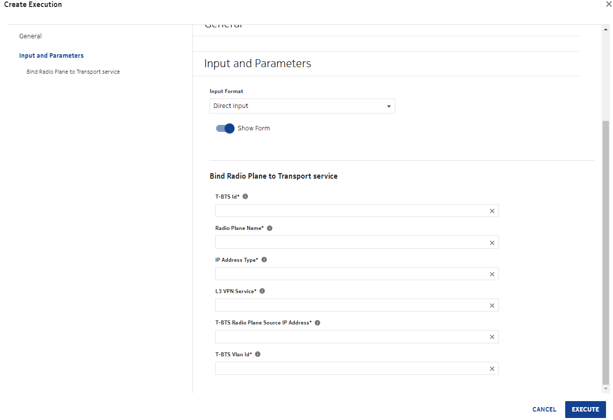
You can bind or rebind a radio plane to a transport service when there is a physical link between a T-BTS port and a backhaul equipment port. To create the binding, click More ![]() and select Bind to L3 VPN in the Radio Plane Bindings view. This launches the Workflow Manager, where you can enter the inputs required for the binding.
and select Bind to L3 VPN in the Radio Plane Bindings view. This launches the Workflow Manager, where you can enter the inputs required for the binding.
Figure 3-6: Creating radio plane binding in Workflow Manager
When the binding is executed, NSP sends a configuration plan to NetAct/MantaRay NM with the specified inputs. In case of IPIF and/or VLANIF creation, userLabels are added to identify objects created via NSP. The binding creates IPIF objects with an ipMtu default value of 1500.
You can view the results of the binding workflow execution in the Workflow Executions history. Logs for this operation are also recorded in the NSP MdmServer.log file.
Note: Only single VLAN ranges (vlanId x, vlanId x) are added or removed from BRGPRT.l2VlanIdList during the binding operation. Multiple VLAN ranges (vlanId x, vlanId y) of BRGPRT.l2VlanIdList are not modified during the binding operation.
Note: When a BTS is linked to several routers containing the same L3 VPN with the same vlan ID, binding this BTS to the L3 VPN is not supported.
Note: Binding 2 radio planes to a VLAN using 2 different IP addresses in the same subnet is not supported. For example, when radio plane 1 is bound to VLAN V using IP address 10.11.12.13/27, radio plane 2 cannot be bound to VLAN V using IP addresses 10.11.12.13/24 or 10.11.12.10/27.
