Serial socket and IP transport services
Overview
Raw socket for serial data transport is a method of transporting serial data over an IP network using L3-based services (IES or VPRN). A raw socket allows direct sending and receiving of IP packets between network devices without any protocol-specific transport layer formatting.
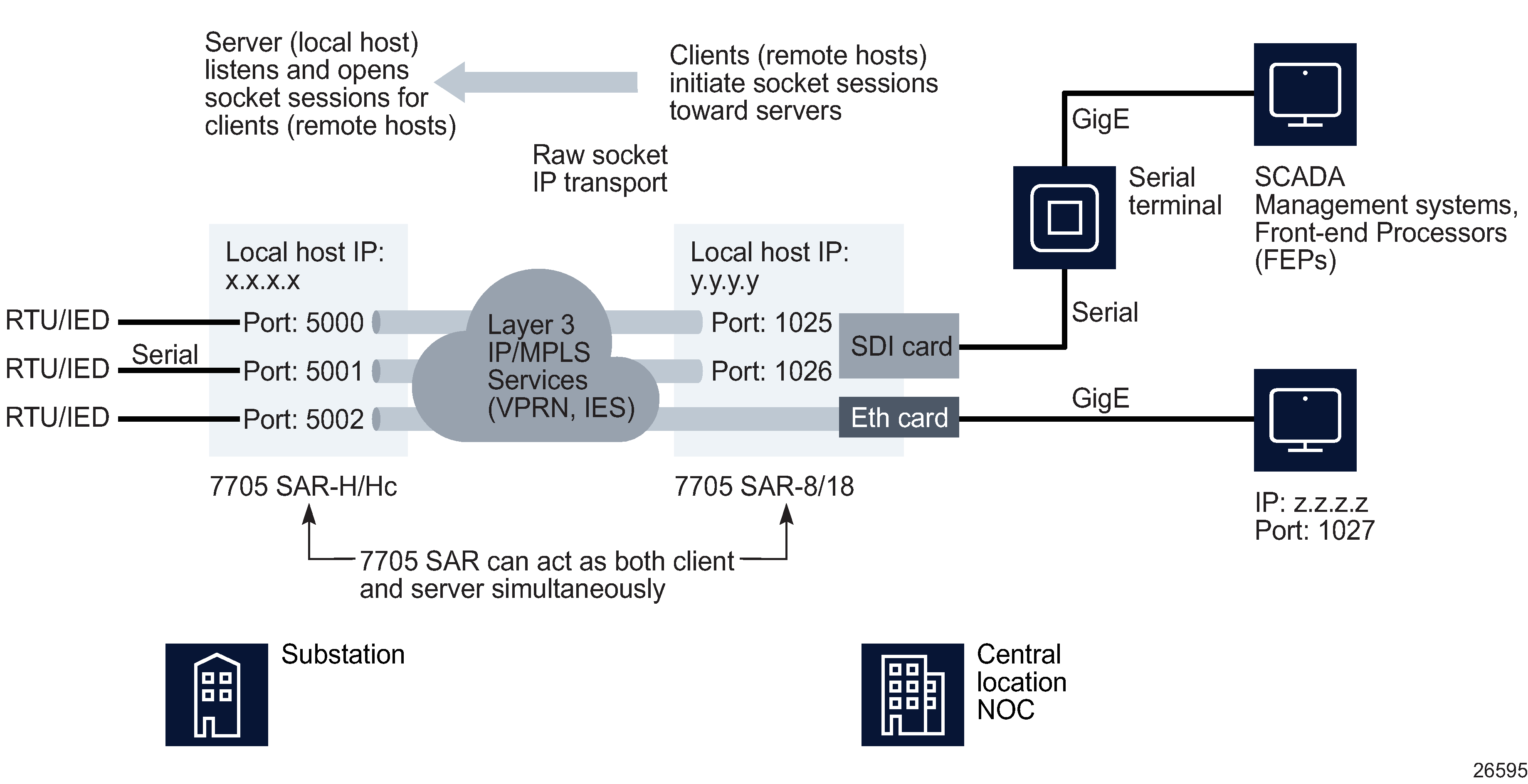
Through local-host and remote-host configurations on an NE, the serial socket IP transport sessions are established to carry serial data over an IP/MPLS network. Incoming serial data is packetized into L3 TCP/UDP packets which ingress IES or VPRN L3 SAPs and are forwarded across an IP/MPLS network. These packets belong to individual sessions between an RTU and SCADA management system/FEP, and are transported as an IP transport sub-service within an IES or VPRN context. The IP transport sub-service uses the local host and remote host details, and port numbers (session parameters) to establish TCP/UDP sessions.
Figure 21-1: Sample serial data transport configuration

For example, SCADA data from RTUs can be transported to FEPs or SCADA controlling units. The serial port-facing RTU is configured as both server and client. Unsolicited messages are communicated by the RTU as a client to the FEPs. When the FEPs request data, the RTUs respond as a server. This transport method is an alternative to C-pipes where the transport medium is an L3 IP/MPLS service instead of L2. For more information about SCADA, see SCADA on the 7705 SAR.
This functionality is supported on the 7705 SAR-8, 7705 SAR-18, 7705 SAR-H and 7705 SAR-Hc, release 8.0 R4 or later, and the 7705 SAR-Hm, Release 15.0 R4 or later.
The benefits of serial sockets are:
-
Lower bandwidth consumption - serial sockets only send data when needed.
-
Multiple head end FEPs can poll RTUs at the same time which avoids serial data collisions from both FEPs at the RTU serial link. Serial sockets can be used to queue and manage data streams and respond back to each at once.
-
A single RTU can send a single data stream to multiple FEPs for unsolicited polls that originate from the RTU.
-
There is no requirement for terminal servers at the FEP locations to convert IP to serial data and back. SCADA controlling units can connect to the head end router via Ethernet to send and receive serial data to and from the RTU.
Serial socket and IP transport configuration setup
-
A 7705 SAR NE with a serial port is connected to local hosts (RTUs) through serial ports acting either as client, server, or both client and server.
-
Serial data over an IES or VPRN L3 interface is carried from the 7705 SAR NEs through another 7705 SAR over IP/MPLS cloud.
-
The remote hosts (SCADA management systems/FEPs) can be connected in one of two ways:
-
Through serial ports of a serial data card on a 7705 SAR-8 and 7705 SAR-18 connected to serial terminals, which is then connected to FEPs/SCADA management systems through GigE interfaces.
-
Through direct TCP/UDP sessions from RTU servers to FEPs/SCADA management systems through GigE interfaces with no serial terminal in between.
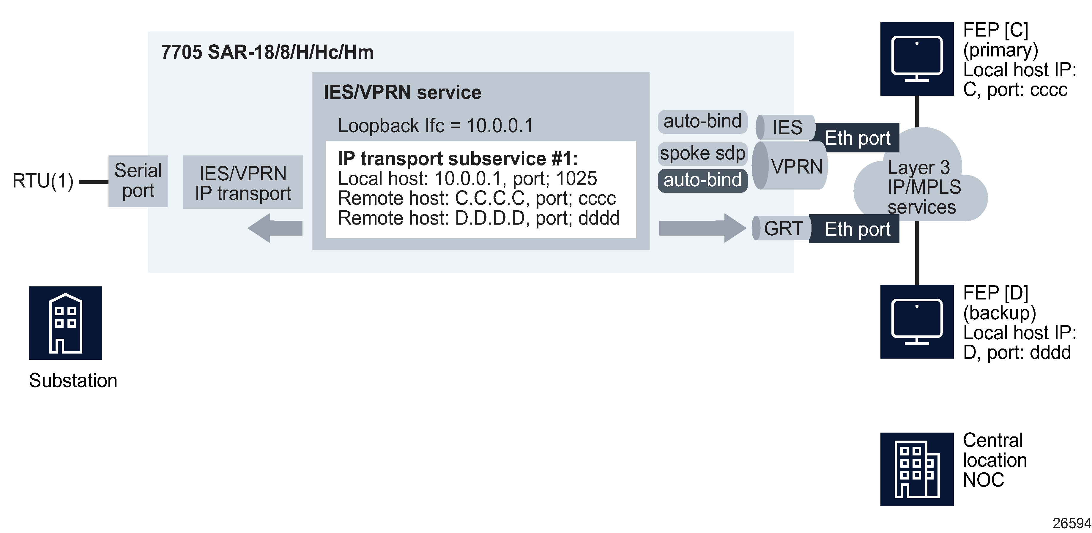
The source and destination IP addresses and port numbers for the IP transport sessions are derived from the local/remote-host configurations associated with each serial port.
-
Figure 21-2: Sample IES/VPRN IP transport configuration

Serial raw socket squelch
A condition may occur where the end device connected to the serial port sends out a continuous stream of data, stopping the far end raw socket or controlling unit from receiving data from other end devices in the network. To resolve this condition, enable the squelch command on the raw socket at the port level (disabled by default) to suppress the socket from receiving any more data from the device connected to the port.
The squelch function is enabled by configuring a delay period that specifies the delay between when the start of a constant character stream begins (e.g. a new packet) and when to start the squelch function. When a constant character stream occurs for the delay timer value, the port is considered locked up, an alarm is raised indicating the lock-up, and the squelching function is triggered. The range of the delay between the alarm and the squelching function is from one to 120s.
To recover from squelch, there are two methods:
-
Manually clear the squelch function for the serial port and put the port in a normal state.
-
Automatically clear the squelch function after a configurable amount of time (one to 120 s) after the squelch function was instantiated to put the serial port back into a normal state.
Socket profile mismatch
A socket profile mismatch occurs when the local properties of a serial raw socket on a 7705 SAR-Hm node with an assigned socket profile no longer match the values defined in the profile. The Socket Profile Mismatch parameter on the RS-232 Socket tab of the port configuration form becomes enabled, and the ReApply button is available. To resolve the mismatch, click on the ReApply button in the Socket Profile panel. The mismatched parameters on the port are configured with the values from the profile.