Sample MPLS configuration
Overview
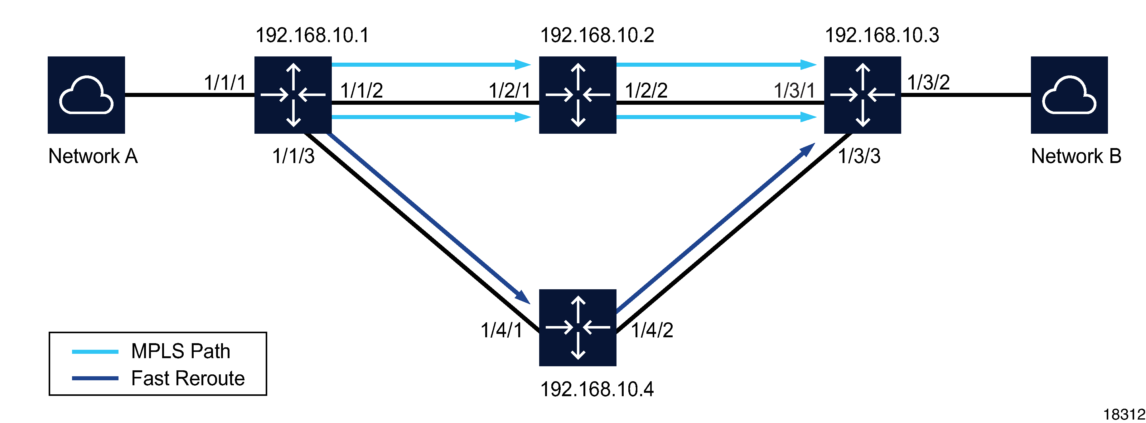
The following figure shows an example of an MPLS service configuration. The actual configuration depends on the specific network requirements.
Figure 31-1: Sample MPLS configuration

Stages
This process describes the high-level tasks that are required to configure the MPLS service example shown in the figure.
Preconfiguration | |
1 |
Before you begin, verify that the following preconfigurations have been made.
|
Configuration | |
2 |
Create an MPLS path. Use the following steps:
|
3 |
Create a Dynamic LSP. Use the following steps: |
4 |
Bind the Dynamic LSP created in Stage 3 to the MPLS path created Stage 2 . |