| Grounding electrode system | |||
|
| GO | ||
UMTS Macrocell sites must be equipped with a grounding electrode system. The cell site grounding, including all cabinets and antenna cable shields, must be bonded to the grounding electrode system.
Electrically conductive materials in the vicinity, that are likely to become energized, must be connected together and to the grounding electrode system in a manner that establishes an effective ground-fault current path.
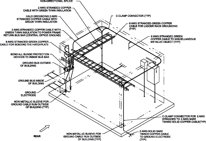
Buried ground conductors must be at least 35 mm2 (2-AWG) bare, solid, tinned copper wire. Exterior ground conductors shall be 35 mm2 (2-AWG), minimum, solid, bare, tinned copper or stranded, insulated (outdoor insulation to be sunlight-resistant) copper cable. The interior ground cable shall be at least 16 mm2 (6-AWG) stranded copper with green insulation, type THWN or equivalent.
For indoor applications, a halo grounding system must be installed with the appropriate number of down conductors with non-directional splices. A sufficient number of pigtails (16 mm2 (6-AWG) stranded copper) shall be provided to bond miscellaneous metallic objects (such as the Z-IDC mounting bracket, louvers, doors, conduits, etc.).
A supplementary grounding conductor (35 mm2 (2-AWG) stranded copper) shall be installed on the top of the ladder rack with sufficient pigtails (16 mm2 (6-AWG) stranded copper) for bonding the cabinet. Each cabinet must be grounded at least at one point, two grounding connections per cabinet is recommended using # 16 mm2 (6-AWG) stranded copper cable.
The supplementary cable shall be bonded to the same bus bar, to which the return of the power cabinet is grounded.
Refer to Grounding and Lightning Protection Guidelines for Wireless System Cell Sites, 401-200-115, for detailed requirements.
Verification of the grounding requirements can be performed using Checklist SP-3 found in Appendix A, UMTS Macrocell site preparation checklists of this document.
Important! All grounding system material (cable, connectors, buses, etc.) must be of high quality materials that resist deterioration and require little or no maintenance.
The following diagram shows a typical halo grounding configuration for a UMTS Macrocell site.
|
|
GO | ||
| © Alcatel-Lucent | |||