| Antenna requirements and interfaces for dual duplex, MCPA and simplex receive (general) | |||
|
| GO | ||
The following are general requirements for RF and GPS antennas when the customer is installing a dual duplex configuration only (No MCPA, no Simplex Receive):
Alcatel-Lucent recommended antenna cables should be used.
RF external surge protector is required at the UMTS Macrocell cabinet end. Use Alcatel-Lucent approved surge protectors or Alcatel-Lucent KS-24577 list 5-A for filters with TTLNA support (1900 and 2100MHz), KS-24577 list 4A for filters without TTLNA support (850 MHz), or KS-24577 list 3A for GPS if used.
All cable runs must be appropriately supported in accordance with the connector and cable manufacturer's instructions and should be terminated with DIN male connectors.
Antenna and cable sweeps must be performed prior to the start of the installation.
The following interfaces are provided at the Macrocell cabinet when the customer is installing or supplying a RxAIT:
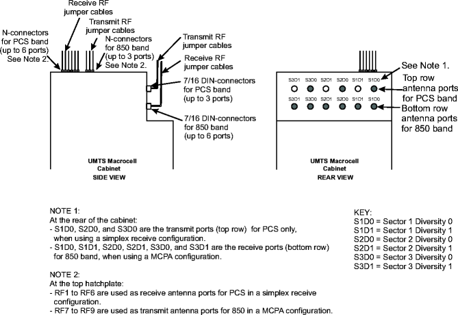
On the receive path, there are twelve RF outputs with N-connectors located at the top hatchplate of the cabinet. They are labeled RF1 to RF6 for the PCS band and RF7 to RF 12 for the 850 band. The top hatchplate is the Lucent demarcation point. See Multi-carrier Power Amplifier (MCPA)/Simplex receive hatchplate for label details.
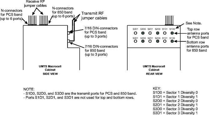
On the transmit path, there are three (max) outputs with 7/16" DIN-connectors located at the rear of the cabinet. The top row connection ports S1D0, S2D0, and S3D0 positions are for the PCS band. The bottom row connection ports S1D0, S2D0, and S3D0 positions are for the 850 band.
Important! The customer must supply the appropriate External RxAIT filter for a simplex receive configuration.
The customer is responsible for providing all cabling from the UMTS Macrocell simplex receive hatchplate to customer's equipment (RxAIT).
The following requirement should be met:
The insertion loss between the UMTS Macrocell cabinet and the RxAIT must be 8 dB. This means the customer may require an external attenuator.
The following interfaces are provided at the UMTS Macrocell cabinet if the customer is installing or supplying a MCPA cabinet:
For the transmit path, there are six RF outputs with N-connectors located at the top hatchplate of the cabinet. They are labeled RF1 to RF3 for the PCS band and RF7 to RF9 for the 850 band.
The top hatchplate is the Lucent demarcation point. See Multi-carrier Power Amplifier (MCPA)/Simplex receive hatchplate for label details.
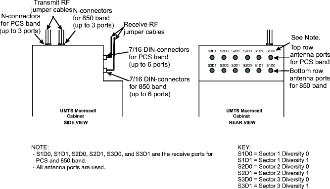
For the receive path, RF jumper connections are made at the rear of the cabinet, but only to the installed filter panels.
The top row connection ports (S1D0, S1D1, S2D0, S2D1, S3D0, and S3D1) are for the PCS band. The bottom row connection ports (S1D0, S1D1, S2D0, S2D1, S3D0, and S3D1) are for the 850 band.
The customer is responsible for providing all cabling from the UMTS Macrocell MCPA hatchplate to the customer's equipment (MCPA).
The transmit signal level at the UMTS Macrocell cabinet interface is +5.2 dBm.
The simplex receive and MCPA interfaces can be provided in a single UMTS Macrocell cabinet. See the following diagram for details.
The following requirements should be met if the customer wants simplex receive and MCPA in the same base station:
For simplex receive (PCS) and MCPA (850), dual band.
The insertion loss between the UMTS Macrocell cabinet and the RxAIT must be 8 dB for the simplex receive PCS configuration. This means the customer may require an external attenuation.
The transmit level at the UMTS Macrocell cabinet interface is +5.2 dB for the MCPA 850 configuration.
The customer is responsible for providing all cabling from the UMTS Macrocell cabinet to the customer equipment RxAIT and MCPA.
The remaining RF jumper connections (9 max) are made at the rear of the cabinet, but only to the installed filter panels.
The top row connection ports (S1D0, S2D0, and S3D0) are for the PCS band. The bottom row connection ports (S1D0, S1D1, S2D0, S2D1, S3D0, and S3D1) are for the 850 band.
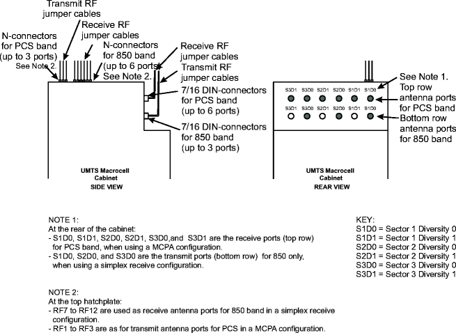
For MCPA (PCS) and simplex receive (850), dual band.
The insertion loss between the UMTS Macrocell cabinet and the RxAIT must be 8 dB for the simplex receive 850 configuration. This means the customer may require an external attenuator.
The transmit level at the UMTS Macrocell cabinet interface is +5.2 dB for the MCPA (PCS) configuration.
The customer is responsible for providing all cabling from the UMTS Macrocell cabinet to the customer equipment RxAIT and MCPA.
The remaining RF jumper connections (9 max) are made at the rear of the cabinet, but only to the installed filter panels.
The top row connection ports (S1D0, S1D1, S2D0, S2D1, S3D0, and S3D1) are for the PCS band. The bottom row connection ports (S1D0, S2D0, and S3D0) are for the 850 band.
Antenna installations for the UMTS Macrocell cabinet shall be performed in accordance with all applicable manufacturer's recommendations, and national laws and regulations.
To ensure correct antenna installation, the antenna installer shall perform all necessary calculations and/or field measurements to evaluate compliance with applicable national laws or regulations regarding exposure to electromagnetic fields. The antenna manufacturer or supplier shall deliver all technical data necessary to perform this compliance evaluation (e.g., antenna gain pattern, antenna dimensions, etc.). Information on the methodology and results of the compliance evaluation shall be available for inspection by officials of the governing authorities.
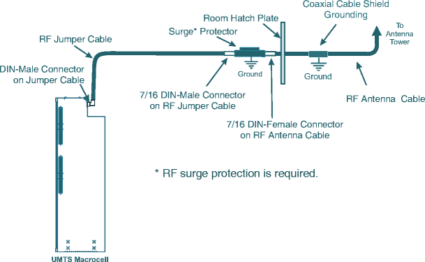
The following diagram shows how to connect a typical single band 850, PCS, or 2100 MHz RF antenna cable with dual duplex filters, single band cabinet.
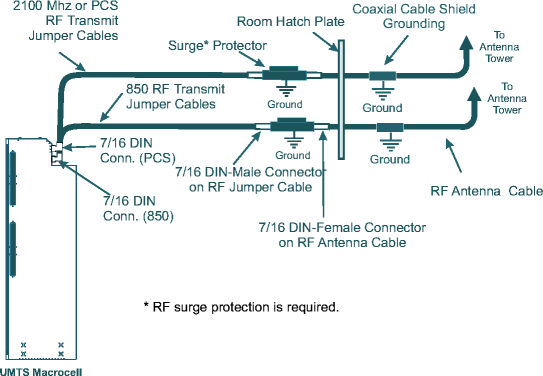
The following diagram shows how to connect a typical RF antenna cable with dual duplex filters, dual band cabinet.
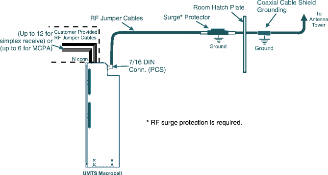
The following diagram shows how to connect a typical RF antenna cable with simplex/duplex filters in a simplex receive or MCPA configuration.
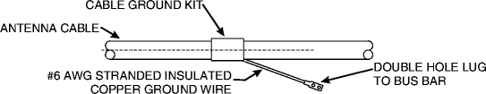
Grounding of the antenna cable outer shield must be performed in accordance with the ground kit manufacturer's instructions and as outlined in the Grounding and Lightning Protection Guidelines for Alcatel-Lucent Network Wireless System Cell Sites, 401-200-115.
The following diagram shows a typical method for grounding the outer shield on an antenna cable.
The cabinet can support six RF antennas, maximum, in a three-sector configuration with transmit/receive diversity.
The RF antenna cable shall satisfy the following requirements:
Impedance: 50 Ω
Attenuation: < 3 dB
The antenna jumper cable end (to the cabinet) must be equipped with a 7/16 DIN male, center-pin straight connector (6.6 to 13.1 feet, 2 to 4 meters).
Surge protection (required).
The antenna cables must be protected by a cable duct or protective cable pipes.
The cable must comply with the X21300 standard.
Jumper cables can be ordered from Alcatel-Lucent in specified lengths.
|
|
GO | ||
| © Alcatel-Lucent | |||