| T1/E1, T3/E3, and OC3/STM1 requirements | |||
|
| GO | ||
Each UMTS Macrocell indoor cabinet supports:
Up to 8 T1/E1 lines, or
One T3/E3 line, or
One OC3/STM1 line
Important! T1/E1, T3/E3, and OC3/STM1 line interfaces are not supported simultaneously. Only one interface type is supported at a time. This applies to 850, PCS, and dual band cabinets.
The T1/E1 facilities must be in place prior to installation of the UMTS Macrocell cabinet. A primary protection device must be supplied and installed by the customer at the NIU as part of site preparation. If required, a balun must also be supplied and installed for converting unbalanced 75 ohm coaxial cable E1 to balanced 120 ohm twisted pair T1 at the Network Interface Unit (NIU).
For each radio cabinet that is being installed, one Z-IDC punchdown block is required as part of site preparation for terminating the T1 cable from the NIU, and must be located within 10 m (35 ft) of the UMTS Macrocell cabinet. Some NIUs contain an internal equivalent punchdown block that can be used for this purpose. Connections from the NIU are made on the NETWORK (rear) side of the Z-IDC block. The Z-IDC punchdown block may be ordered from Alcatel-Lucent.
When a single conductor is terminated in an insulation displacement contact (IDC) slot, a maximum conductor size or 0.5 mm2 (20-AWG) may be used. However, if two conductors are to be terminated in the same IDC slot then a maximum conductor size of 0.34 mm2 (22-AWG) may be used.
A fully-configured indoor cabinet requires eight twisted-pair 0.25 mm2 (24-AWG) cables from the punchdown block to the cabinet. These cables are connectorized at the cabinet end with a 25 pin male D-sub. The other end of each cable is punched down, by the installer at the time of installation, at the EQUIPMENT side of Z-IDC blocks. The cables are 10 m (35 ft) long and are color-coded in accordance with the standard telephone industry code for eight twisted-pair cable.
Important! In the United States, refer to Article 800 of the National Electrical Code, NFPA 70, for selection and installation of the primary protector. In Canada, refer to Section 60 of the Canadian Electrical Code, Part I, CSA C22.1 for selection and installation of the primary protector.
For International applications, refer to ITU K.11, Principles of Protection Against Overvoltages and Overcurrents.
For further information concerning installation of primary protectors, see Telcordia TR-NWT-000937.
Important! If the Z-IDC punchdown block is used, a Krone punchdown tool (or equivalent) will be required to terminate the twisted-pair cables at the Z-IDC punchdown block. The Z-IDC punchdown tool can be obtained from CommScope (suplr-key: ZIDC-WT1) or from KRONE (suplr-key: 6417 2 055-01).
The T3/E3 facilities must be in place prior to installation of the UMTS Macrocell cabinet. The required coax (two single cables initially) must be supplied and installed to the T3/E3 facility cabinet.
Important! Coax cables should be handled and installed as per manufacturer's instructions to avoid cable damage.
Sufficient cable length must be routed and coiled to allow for future connection to the left oval hatchplate located at the top of the UMTS Macrocell cabinet. The appropriate number of T3/E3 cables must be available at the site prior to installation (two cables per cabinet initially).
There are two sets of coax cable available from Alcatel-Lucent:
15.24 m (50 ft) coax cable with BNC connector at one end, and no connector at the opposite end (BNC supplied loose).
30.48 m (100 ft) coax cable with BNC connector at one end, and no connector at the opposite end (BNC supplied loose).
The recommended coax cable consists of a single conductor 0.5 mm2 (20 AWG) solid silver-platted copper conductor, beldfoil +58% tinned copper braid with an overall diameter of 0.235.
The OC3/STM1 facilities must be in place prior to installation of the UMTS Macrocell cabinet. The required fiber cable (one-pair) must be supplied and installed to the OC3/STM1 facility cabinet.
Important! Fiber cables should be handled and installed as per manufacturer's instructions to avoid cable damage.
Sufficient cable length must be routed and coiled to allow for future connection to the left oval hatchplate located at the top of the UMTS Macrocell cabinet. The appropriate number of OC3/STM1 cables must be available at the site prior to installation (one cable per cabinet).
There are two types of fiber cables available from Alcatel-Lucent:
One-pair fiber cable, single mode, LC straight to LC straight, with protective cap, 15.24 m (50 ft) .
One-pair fiber cable, single mode, LC straight to LC straight, with protective cap, 30.48 m (100 ft) .
A customer provided fiber cable protection system may be required to prevent cable damage during equipment operation or maintenance. An Alcatel-Lucent part is available from LWS (Comcode 408349983, quantity 2).
If there is extra cable remaining after interconnection of fiber cable at both ends and the cable is not jacketed, a customer provided fiber slack storage reel may be required to prevent equipment malfunction or cable damage. The fiber cable currently available from Alcatel-Lucent is jacketed.
The wiring interfaces for the indoor UMTS Macrocell primary cabinet are covered in the following two figures:
T1/E1, T3/E3, and OC3/STM1
User alarms.
Refer to the figure below for an overview illustration of T1/E1, T3/E3, and OC3/STM1 and user alarm wiring using Z-IDC punchdown blocks. T3/E3 and OC3/STM1 lines do not use Z-IDC punchdown blocks.
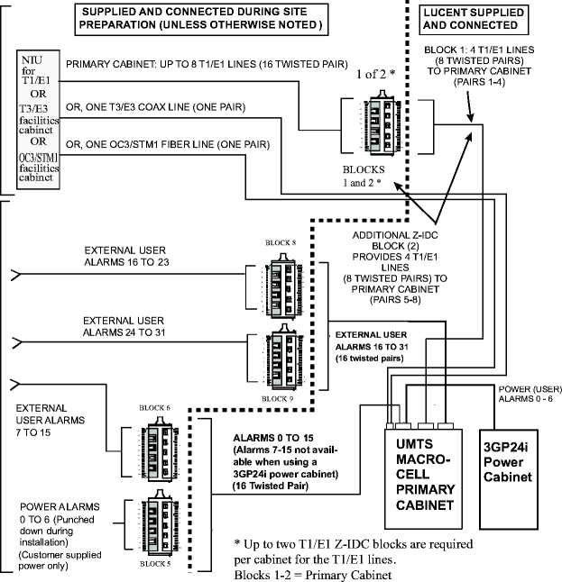
The figure and table below illustrates the position assignments of the Z-IDC punchdown blocks within the wall mounting bracket for the primary cabinet.

|
Z-IDC punchdown block position number |
URC in primary cabinet |
What assigned |
|
1 |
First URC II |
One to four T1/E1 lines |
|
2 |
First URC II |
13 to 16 T1/E1 lines |
|
3 |
N/A |
Blank (Possible future T1/E1 lines |
|
4 |
N/A |
BLANK (Possible future T1/E1 lines) |
|
5 |
N/A |
User Alarms 0 to 6 |
|
6 |
N/A |
User Alarms 7 to 15 |
|
7 |
N/A |
Blank (Possible future T1/E1 lines) |
|
8 |
N/A |
User Alarms 16 to 23 |
|
9 |
N/A |
User Alarms 24 to 31 |
|
10 |
N/A |
Blank (Possible future T1/E1 lines) |
| 1 | Each URC II supports up to eight T1/E1 lines. |
| 2 | T1/E1 lines 1-4 are connected to URC II via IOU. |
| 3 | T1/E1 lines 13–16 are connected to URC II via SECB. |
The following diagram shows a typical configuration for the T3/E3 facilities cabinet to the left oval hatchplate at the UMTS Macrocell end for T3 input lines.

Important! The shielding coax cables must be grounded at the T3/E3 facilities cabinet end, and at the UMTS Macrocell cabinet end. Alcatel-Lucent recommends that the recommended tool, ITE No. R-5648B or R-5648C be used for the ferrule outer conductor, and ITE No. R-6106 be used for center pin conductor, to connect the optional coax cable with BNC loose connector provided by Alcatel-Lucent at the T3/E3 facility cabinet.
CAUTION
Equipment Damage
Cable damage
To prevent cable damage when handling and installing the coax cable as part of site preparation, do not exceed maximum bending radius of ten times the outside diameter at any point of the cable run.
The following diagram shows a typical configuration for the OC3/STM1 facilities cabinet and the connection to the URC II in the UMTS Macrocell.
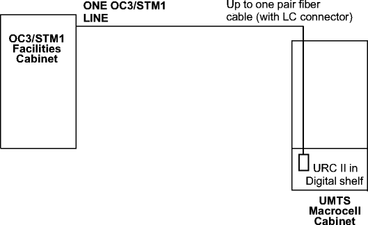
Important! The provided Alcatel-Lucent optional fiber cables are connectorized LC straight at the customer's OC3/STM1 facilities cabinet end. If a different connector is used, a customer provided adapter will be required for interface with the OC3/STM1 facilities cabinet.
CAUTION
Equipment Damage
Cable damage
To prevent cable damage when handling and installing the fiber cable as part of site preparation, do not exceed maximum bending radius of 15 times the outside diameter at any point of the cable run. Do not twist, pull, or kink the fiber cable
The following diagram shows a typical configuration for the NIU and terminal block for T1 input lines.

WARNING
Equipment Damage
The Z-IDC punchdown tool (ITE No. R-6097) must be used when punching down wires on a Z-IDC punchdown block. Use of any other tool will damage the Z-IDC punchdown block.
Important! The customer must make the connections in the following tables as part of site preparation.
As previously stated, one to three Z-IDC punchdown blocks are required as part of site preparation for terminating the T1 cable from the NIU. The following three tables (one for each URC) provide the punchdown information.
|
T1 cable (URC II) |
Pair No. |
Function Tx/Rx, Tip/Ring |
Z-IDC Network Side Punchdown block and position for URC (see Note) |
|
Primary Cabinet Block - Position | |||
|
LINE |
1 |
Tx T |
1-1 Upper |
|
Tx R |
1-1 Lower | ||
|
2 |
Rx T |
1-2 Upper | |
|
Rx R |
1-2 Lower | ||
|
LINE |
3 |
Tx T |
1-3 Upper |
|
Tx R |
1-3 Lower | ||
|
4 |
Rx T |
1-4 Upper | |
|
Rx R |
1-4 Lower | ||
|
LINE |
5 |
Tx T |
1-5 Upper |
|
Tx R |
1-5 Lower | ||
|
6 |
Rx T |
1-6 Upper | |
|
Rx R |
1-6 Lower | ||
|
LINE |
7 |
Tx T |
1-7 Upper |
|
Tx R |
1-7 Lower | ||
|
8 |
Rx T |
1-8 Upper | |
|
Rx R |
1-8 Lower | ||
|
EXAMPLE 1-3 Lower = Block Number 1, Position 3, Lower | |||
|
The Z-IDC positions 9 and 10 are not used. Unused T1 cables at the customer's NIU must not be looped back towards the UMTS Macrocell cabinet during normal operation. | |||
|
|
GO | ||
| © Alcatel-Lucent | |||