| Ethernet interconnect requirements | |||
|
| GO | ||
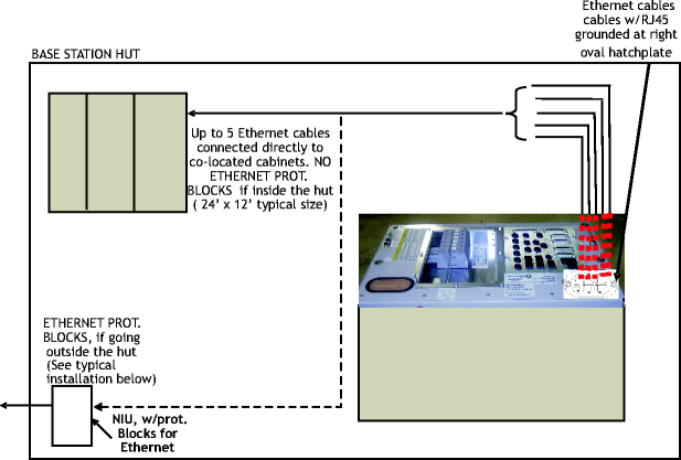
The UMTS Macrocell cabinet may be equipped with an Ethernet switch which can provide up to five output 10/100 Mb switched RJ45 ports.
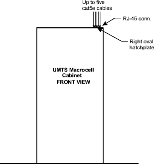
Up to five cat5e cables for Ethernet connections must be in place prior to installation of the UMTS Macrocell cabinet when equipped with an optional Ethernet switch.
The five cat5e cables for Ethernet connection shall be connected to co-located cabinets within a hut only.
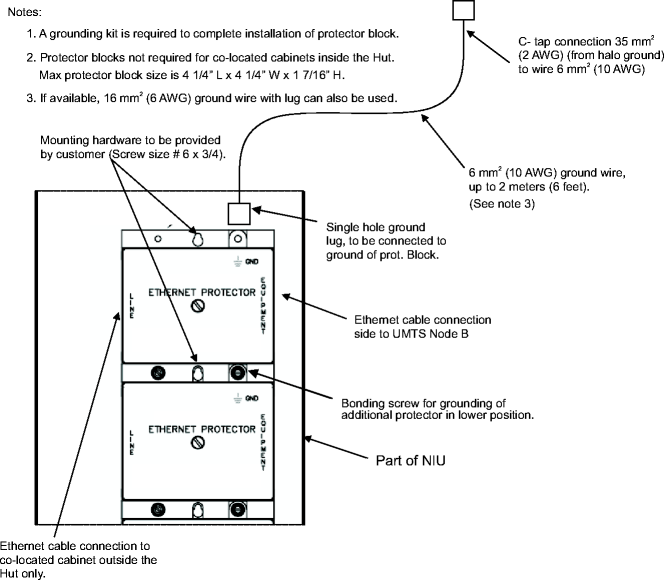
Important! An Ethernet protector block (primary and secondary protection) is required per Ethernet port at the NIU if the Ethernet connections are to be connected outside the hut. Alcatel-Lucent may provide the Ethernet protector blocks if required, which include connection for grounding. Mounting hardware shall be provided by the customer.
If protector blocks are used, they shall be installed as part of site preparation. See example below for a typical installation.
Sufficient cable length must be routed and coiled to allow for future connections of the Ethernet switch located at the top of the UMTS Macrocell cabinet.
There are two sets of cat5e, 4-pair, shielded twisted pairs (STP), RJ-45 connectorized cables available that may be purchased from Alcatel-Lucent:
15.24 m (50 ft) cat5e, 4-pair (STP), RJ-45 connectorized at both ends
30.48 m (100 ft) cat5e, 4-pair (STP), RJ-45 connectorized at both ends
The following figure shows an example of a Ethernet protector block typical installation for two blocks. Make final installation per instructions provided with the protector block kit.
The following figure shows how to run the cat5e cables from the hatchplate located at the top right of the UMTS cabinet to the up to five co-located cabinets inside a hut
|
|
GO | ||
| © Alcatel-Lucent | |||