| Power system requirements | |||
|
| GO | ||
This section specifies the mechanical, electrical, and environmental requirements the power system shall meet. Unless specified, the following requirements apply to indoor power systems only.
Alcatel-Lucent strongly recommends that the power system meet the same environmental, safety and regulatory requirements as the Alcatel-Lucent equipment to maintain its safety and regulatory certification.
The following table provides the interface requirements required to connect the UMTS Macrocell cabinet to a customer supplied power system.
|
Interface |
Requirement |
|
Mechanical interface |
The customer is responsible for specifying all the mechanical requirements for the power system such as dimensions, weights, anchoring, grounding, conduit/cable interfaces, and installation features. |
|
UMTS Macrocell cabinet interfaces |
All the power system electrical interfaces are located at the top of the UMTS Macrocell cabinet. For dimensions of the UMTS Macrocell cabinet refer to Chapter 2, Overview of UMTS Macrocell indoor base station of this document. Note: Under no circumstances shall any modification (e.g. drilling) be made to the UMTS Macrocell cabinet(s) unless the modification is covered by a Alcatel-Lucent “Change Notice”. |
|
Electrical interface requirements |
The electrical interfaces between the power system and the UMTS Macrocell cabinets consist of DC power, and power system alarms. All cabinets receive DC power independently from the power system. All power system alarms interface with the UMTS Macrocell Primary cabinet only. |
The following diagram shows the electrical interfaces of a typical power system.
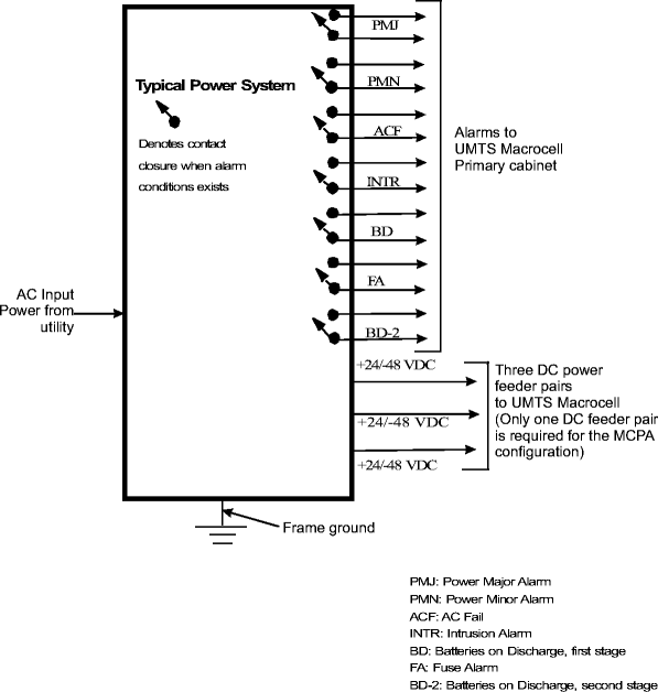
The nominal +24/-48 VDC power supplied to the UMTS Macrocell cabinet(s) shall meet the requirements specified in this section. All of the electronic equipment related to processing of calls, and the fans in the UMTS Macrocell cabinet are powered from the +24/-48 VDC power supplied to the equipment. The DC power system shall be capable of providing constant power to the equipment over the entire range of environmental condition for the “country of use.”
The UMTS Macrocell has three 24 VDC input power feeds, each rated at 120 A, or 48 VDC input power feeds, each rated at 90 A.
The typical power level is the DC power consumption expected while the site is operating with “busy hour” traffic and an ambient temperature between 20° and 25° Celsius. The UMTS Macrocell cabinet(s) have constant power load characteristics. The power levels in the table are based on an input of +27.25 VDC for +24 VDC and 54.5 VDC for -48 VDC. For various UMTS configurations, the typical and maximum DC power requirements and number of required rectifiers are provided in the Alcatel-Lucent ERD (ER_0202_0001). See Appendix F, Power requirements and battery reserve times for UMTS Macrocell Indoor cabinets.
Each UMTS Macrocell cabinet requires three DC feeds, as shown in the table on the next page. Only one DC feeder is required for MCPA configurations.
Alternate wire gauges may be used for the DC feeders, but shall be sized to limit the round trip voltage drop between the power system output terminals and the UMTS Macrocell input terminals to less than one volt. A current level equal to 80% of the circuit breaker current rating specified shall be used for this calculation. The wire used for the DC feeders shall be rated for the environmental condition in which it is used and shall be rated and sized according to the applicable sections of the National Electrical Code (NFPA 70) or the Canadian Electrical Code, Part I (CSA C22.1) for NAR markets, IEC 60364 for non-NAR markets, or the local electrical code in use. The circuit breaker characteristics shall be equivalent to Airpax Inc. model LEL/LML, circuit breakers with type 51, DC trip delay curve characteristics.
DC feeds must be type Class B stranded wire, rated for 90 degrees Celsius.
Important! If Class I stranded wire is used, a ferrule connector must be crimped to the end of the wire to avoid short circuit damage to the terminal block.
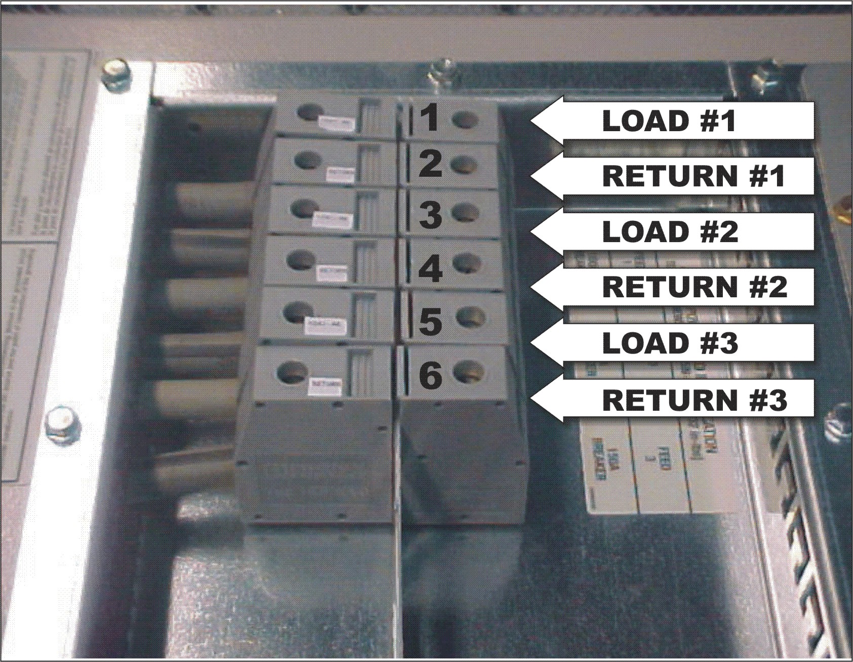
The DC terminal block is located at the top of the UMTS Macrocell cabinet. (See figure on the next page).
Important! The connections at the DC terminal block must be torqued to 6 Nm.
|
DC feeders and connection interface | |||||||
|
Feeder #1 |
Feeders #2, #3 * |
Maximum wire size at DC terminal block | |||||
|
Circuit breaker (Amps) |
Wire size (AWG) |
Max. Length (Feet) |
Circuit breaker (Amps) |
Wire size (AWG) |
Max. Length (Feet) | ||
|
+24 V cabinet |
150 |
1/0 |
11 m (35 ft) |
150 |
1/0 |
11 m (35 ft) |
50 mm2 (1/0 AWG) |
|
-48 V cabinet |
90 |
2 |
11 m (35 ft) |
90 |
2 |
11 m (35 ft) | |
|
* Feeders #2 and #3 are not required for MCPA configurations. MCPA uses Feeder 1 only. | |||||||
| 1 | DC wires and lugs must be rated for 90 degrees Celsius installations. |
| 2 | For longer wire runs, wire size and circuit breaker ratings must be calculated as specified above, in this section. |
UMTS Macrocell DC power terminal block (Front -View)
The DC input terminals of the UMTS Macrocell primary cabinet are equipped with electrolytic capacitors to reduce noise, ripple, and the effect of transients. The capacitors can draw a high inrush current when power is first applied to the UMTS Macrocell.
|
UMTS Macrocell |
Inrush current (Amps) |
Time (Milliseconds) |
|
+24 VDC |
400 to 1250 |
up to 1 |
|
-48 VDC |
600 to 1200 |
up to 1 |
The circuit breakers providing DC power to the UMTS Macrocell must be able to withstand this high inrush current. The Airpax Inc., model LEL/LML, circuit breakers with type 51, DC trip delay curve characteristics is rated to withstand the inrush current.
The following table provides the overload trip characteristic for the Airpax circuit breaker with type 51 delay characteristics, used in UMTS Macrocell +24/-48 VDC. If an alternate circuit breaker is used, it must have equivalent overload trip.
|
Airpax model LEL/LML type 51 Overload Trip Time (Seconds) | ||||||||
|
Rating |
100% |
125% |
150% |
200% |
400% |
600% |
800% |
1000% |
|
Time (sec.) |
No trip |
0.5 - 6.5 |
0.3 - 3 |
0.1 - 1.2 |
0.3 - 0.5 |
0.011- 0.25 |
0.004 - 0.1 |
0.004 - 0.08 |
The normal DC input voltage range, the set point of float voltage for the battery and the maximum float voltage set points for the UMTS Macrocell, are provided in the following table.
|
UMTS Macrocell |
Normal input voltage range (volts DC) |
Set point of float voltage (volts DC) |
Maximum float voltage (volts DC) |
|
+24 VDC |
20 to 28.1 |
27.24 |
28.1 |
|
-48 VDC |
-42.2 to -56.2 |
-54.48 |
-56.2 |
The DC power system output voltage shall remain within the range specified in the table above. If a failure occurs with the DC Power system controller
The DC voltage shall be regulated to within ± 0.5% of the voltage set in the table above under all conditions of line, load and temperature.
The DC voltage at input of the UMTS Macrocell shall not overshoot more than 3.5% of the set voltage in the table above for a period of more than 100 milliseconds, under any conditions.
The following table provides ripple and noise requirements. This requirement applies, with or without batteries connected to the system, however the system is not intended to operate without batteries.
|
UMTS Macrocell |
Ripple voltage mVpp (0 to 100 MHz) |
Ripple voltage mVpp (mVRMS) |
DC system noise mV (psophometric) |
|
+24 VDC |
Not to exceed 100 |
50 |
Less than 1 |
|
-48 VDC |
Not to exceed 250 |
100 |
Less than 2 |
For any step-load demand change of 10% to 90%, or 90% to 10%, on the DC power system, the DC input voltage to the UMTS Macrocell shall remain within 5.0% and return to the 0.5% regulation band within 300 milliseconds.
In the event of a commercial power failure, Alcatel-Lucent recommends the DC power provided to the UMTS Macrocell be backed up for a minimum of 30 minutes. The DC power to the equipment shall not be interrupted during the transition from normal operation to backup operation and vice versa.
Important! If the DC power supplied to the UMTS Macrocell cabinets is not equipped with backup power, undesirable performance may be experienced during interruption and/or transients to the AC input power.
The DC power source may shut down if the output voltage reach the following values:
|
UMTS Macrocell |
Maximum Voltage range (Volts DC) |
Maximum Voltage for up to one second |
|
+24 VDC |
28.1 to 30 |
30 |
|
-48 VDC |
-56.2 to -60 |
-60 |
| 1 | The DC power system shall not provide sustained voltage to the UMTS Macrocell at the maximum voltage values, for more than one second, as shown in the table above. If a power system failure occurs which causes loss of regulation resulting in voltage levels given in the table above stated as the “maximum voltage range”, the power system shall shutdown or clamp its output voltage below -56.2 VDC (for –48 VDC systems) and 30 VDC (for +24 VDC systems) until the problem is corrected. |
The DC power system shall be designed to prevent surge transients at its input passing through to the output and causing voltage transient in excess of 30 Volts (for +24 VDC systems) or -60 Volts (for -48 VDC systems) the UMTS Macrocell cabinet(s). In addition, surge protectors and/or surge suppressors may be required to limit surge voltages to less than 30 Volts (for +24 VDC systems) and -60 Volts (for -48 VDC systems).
The +24/-48 VDC return conductors shall be bonded to the frame ground system at the output of the DC power system. For proper site grounding of the equipment, refer to Grounding and Lightning Protection Guidelines for Alcatel-Lucent Network Wireless System Cell Sites, 401-200-115.
Each alarm generated by the power system shall be provided by a set of isolated dry relay contacts, an “alarm state” may be indicated by a “closed circuit” or an “open circuit”. If an alarm condition is indicated by a “closed circuit”, the DC power system alarm contacts shall present a contact closure when the alarm circuit fails or looses power. If an alarm condition is indicated by a “open circuit”, the DC power system alarm contacts shall present an “open circuit” when the alarm circuit fails or looses power. The resistance of a “closed circuit” shall be less than 100 ohms. The resistance of an “open circuit” shall be greater than 1 megohms. The table on the next page provides for the standard power system alarm assignments and connection points for the UMTS Macrocell cabinet.
The UMTS Macrocell has 25 additional external user alarm positions provided through the Z-IDC blocks, as shown in Chapter 7, T1/E1, T3/E3, OC3/STM1, user alarm, and Ethernet facility requirements of this document. These user alarms are available at the UMTS Macrocell cabinet to alarm additional equipment. The UMTS Macrocell software configuration must be programmed to report an “open circuit” or “closed circuit” for an alarm condition. (The UMTS Macrocell software is configured for a “contact closure” for power system alarms. A software change to the User Alarm definitions is required to announce a power system an “open circuit” as an alarm condition).
The following table lists the minimum set of alarm functions that must be provided to alert and announce power system failures. There are seven (7) alarms that are specially dedicated and provisioned ONLY for power.
|
Power alarm cable | |||
|
Z-IDC terminal block |
Alarm function |
Alarm # |
Position on Z-IDC terminal block (Network side) |
|
Power alarms (Locations 1-7) |
Power Major (PMJ) |
User 0 Alarm |
5-1 Upper 5-1 Lower |
|
Power Minor (PMN) |
User 1 Alarm |
5-2 Upper 5-2 Lower | |
|
AC Fail (ACF) |
User 2 Alarm |
5-3 Upper 5-3 Lower | |
|
Power Cabinet Intrusion (INTR) |
User 3 Alarm |
5-4 Upper 5-4 Lower | |
|
Batteries on Discharge (BD) |
User 4 Alarm |
5-5 Upper 5-5 Lower | |
|
Fuse Alarm |
User 5 Alarm |
5-6 Upper 5-6 Lower | |
|
Batteries on Discharge (BD) 2 |
User 6 Alarm |
5-7 Upper 5-7 Lower | |
| 1 | If the DC power system does not support some of the power alarms described above, it is strongly recommended that the customer not connect alarms from other equipment to these power alarms. Because these power alarms are reported back to the core network, it is important that the customer maintain circuit integrity to avoid misinterpretation when equipment alarms and failures are reported. Each specific power alarm function should, therefore, maintain its identity throughout the network and should not be used for any other purpose. |
Two Z-IDC blocks (see figure below) must be installed so power and user alarms can be connected to the UMTS Macrocell. If alarms are required for outdoor components (e.g., tower light) they should be connected through the NIU and the Z-IDC block. Insulation displacement contact (IDC) terminals interface the power system alarms with the UMTS Macrocell cabinet user alarms. Alarm wire pairs are punched down at terminals 1 to 7 in the table shown above. The ITE No. R-6097 (KRONE) punchdown tool is needed to terminate the alarm wire pairs at the IDC terminals. The IDC terminals accept 0.34 mm2 (22-AWG) - 0.25 mm2 (24-AWG) wire.

|
|
GO | ||
| © Alcatel-Lucent | |||