| UMTS Macrocell base station overview | |||
|
| GO | ||
The following diagram provides a typical overview of the UMTS Macrocell base station when connected to a 3GP24i power cabinet.
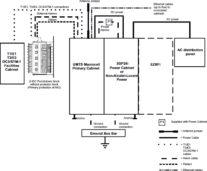
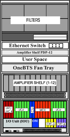
The UMTS Macrocell cabinet contains UMTS radio communication equipment, amplifiers, alarms, a T1/E1, optional T3/E3, and OC3/STM1 facilities interface, Ethernet switch, filters, and a user alarm interface. The UMTS Macrocell cabinet can be shipped with components that provide 1 to 2 carriers maximum (up to 4 carriers in the future), and 1 to 3 sectors, maximum. The figure below shows an interior view of the UMTS Macrocell cabinet.
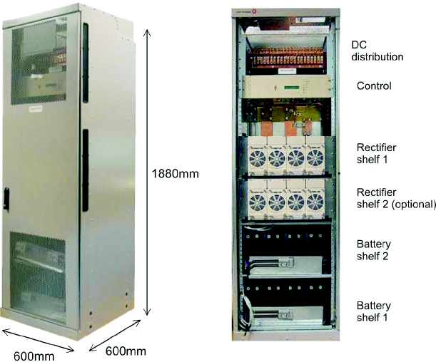
The 3GP24i power cabinet supplies +24 VDC and contains AC/DC rectifier modules, a controller (with alarms), batteries, and distribution elements.
The EZBFi battery module is used with the 3GP24i power cabinet. It provides supplementary battery backup for the batteries that are located inside the 3GP24i power cabinet. This design is modular. Additional battery strings can be added in the field to extend battery backup time. The first battery module, which goes at the base, is shown in the figure below. Additional (add-on) modules contain one or two battery shelves. Each shelf contains four L1 batteries (two strings).
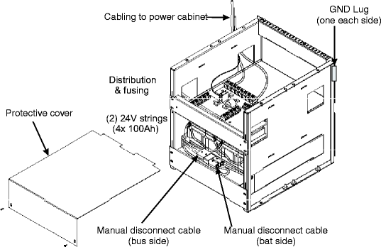
For information on installing the EZBFi battery frame, see EZBFi Modular Battery System Installation Manual for +24V and -48V, 401-703-507.
The following table specifies the attributes of a UMTS Macrocell indoor primary cabinet.
|
UMTS Macrocell |
Attributes |
|
Frequency bands |
PCS 1900 MHz Cellular 850 MHz Dual Band 850/1900 MHz 2100 MHz Dual Band 850/2100 MHz (FUTURE) |
|
Indoor operating temperature |
-5°C to +40°C (continuous) -5°C to +50°C (short-term) |
|
Electrical rating |
Three (3) lines: 24 VDC, 120 A each Three (3) lines: -48 VDC, 90 A each |
|
Power and battery |
3GP24i power cabinet EZBFi battery frame |
|
Sectors |
up to 3 sectors |
|
Carriers |
1-2 (1-4 future) per cabinet (Single Band) 1 850 (1-2 future) / 1 1900 (1-2 future) (Dual Band) |
|
Filters |
Dual Duplex Block Simplex/Duplex |
|
Facilities for R04.03: T1/E1 facilities T3/E3 facilities option OC3/STM1 facilities option Ethernet switch option |
- Up to 8 T1/E1s, or One, or One, or - Up to 5 output ports |
|
Antenna |
RF: Up to 6 for Single Band - Duplex RF: Up to 18 for Dual Band - Simplex and MCPA GPS: optional |
|
User alarms |
32 |
|
User relay |
Optional (hardware ready) |
|
|
GO | ||
| © Alcatel-Lucent | |||