Root cause analysis overview
Introduction
You can use the CPAM as a tool for determining the root cause of a problem, such as a service outage or service degradation. For example, you can view the time of a service outage to determine how the network was behaving at that time. The CPAM records IGP network events—such as router and network LSAs—in the database.
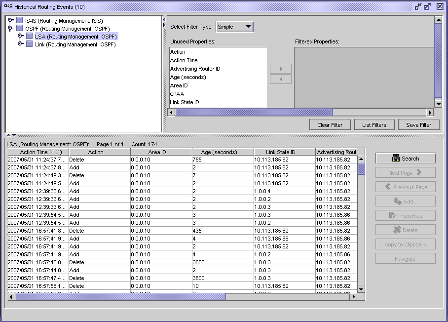
You can specify whether the events are recorded on each CPAA on a per-CPAA basis, and on a protocol-by-protocol basis (OSPF, OSPF-TE, ISIS-TE). You can use size constraint policies to control the number of events stored in the database. You can export historical data using the XML API or the NFM-P GUI. The following figure displays the CPAM search form for captured events.
Figure 14-1: Browse network-level protocol objects
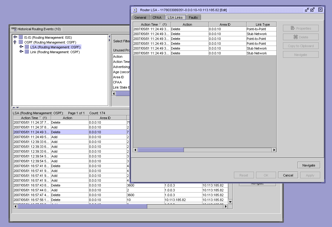
The following figure shows the drill-down of captured events into detailed LSA information.
Figure 14-2: Browse network-level protocol events
The recording of IGP router events into a database allows you to filter and analyze historical data to determine if any significant routing events occurred. The CPAM allows you to highlight routers and links on the topology map that were affected by a router event. All window entries, such as LSA, follow the standard NFM-P filtering and sorting functionality.
Note: See Chapter 8, Path and prefix monitoring for more information about configuring size constraint policies.
You must enable the Keep Event History parameter on the CPAA configuration form to save historical events. See To deploy a CPAA to monitor a BGP AS for information.
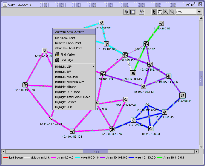
You can select map objects that are affected by specific protocol events. The following figure shows the Find Vertex and Find Edge contextual menu options that you can use to search for map objects.
Figure 14-3: Find Vertex and Find Edge menu options
Next hop FEC overlay
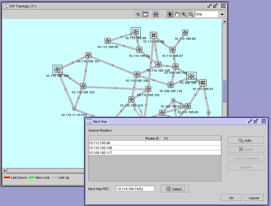
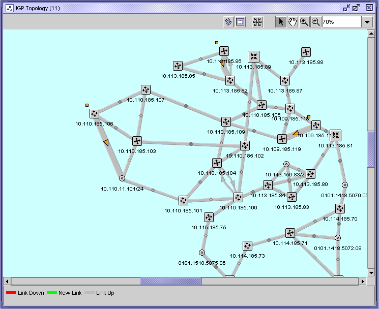
You can view the next hop for a FEC from a set of routers that use the CPAM. By typing in a next hop prefix and selecting a group of routers, the next hops to a FEC are highlighted with arrows on the appropriate topology map. The next hop view can be used to search for suspicious routing of an address in the network. ECMP for next hop FEC overlay allows more than one link to be highlighted from a router. Routers that do not have a next hop for a FEC are displayed in an error dialog.
The following figure shows the next hop FEC configuration form.
Figure 14-4: Next hop FEC overlay configuration
The following figure shows the next hop FEC overlay results on the topology map.
Figure 14-5: Next hop FEC overlay results
© 2024 Nokia. Nokia Confidential Information
Use subject to agreed restrictions on disclosure and use.