Overview
This chapter describes the concept of end-to-end network slicing and how transport slices relate to NSP functionality as Transport Slice Controller (TSC). This chapter covers the following topics:
Note: Please contact your NSP PLM representative to assess your network and use-case if you intend to deploy TSC.
What is end-to-end network slicing?
End-to-end network slicing is a technology for concurrent delivery of differentiated services and a key component of moving wireless network use-cases toward a service-driven evolution that supports meeting SLAs deterministically across end-to-end network resources. Network slices are independent, logical self-contained networks representing common physical or virtual network infrastructure that extends from end devices to application servers and includes all intermediate functions and domains.
Network slicing is beneficial to various applications, including the following:
Network slices can include virtual and physical network functions, cloud infrastructure, transport/connectivity, augmented services (for example, network analytics and security services), as well as application functions. Network slices are orchestrated to form service-specific logical networks running on the same physical network that meet certain Service Level Objective (SLO) attributes such as data speed, capacity, latency, reliability, availability, coverage, and security.
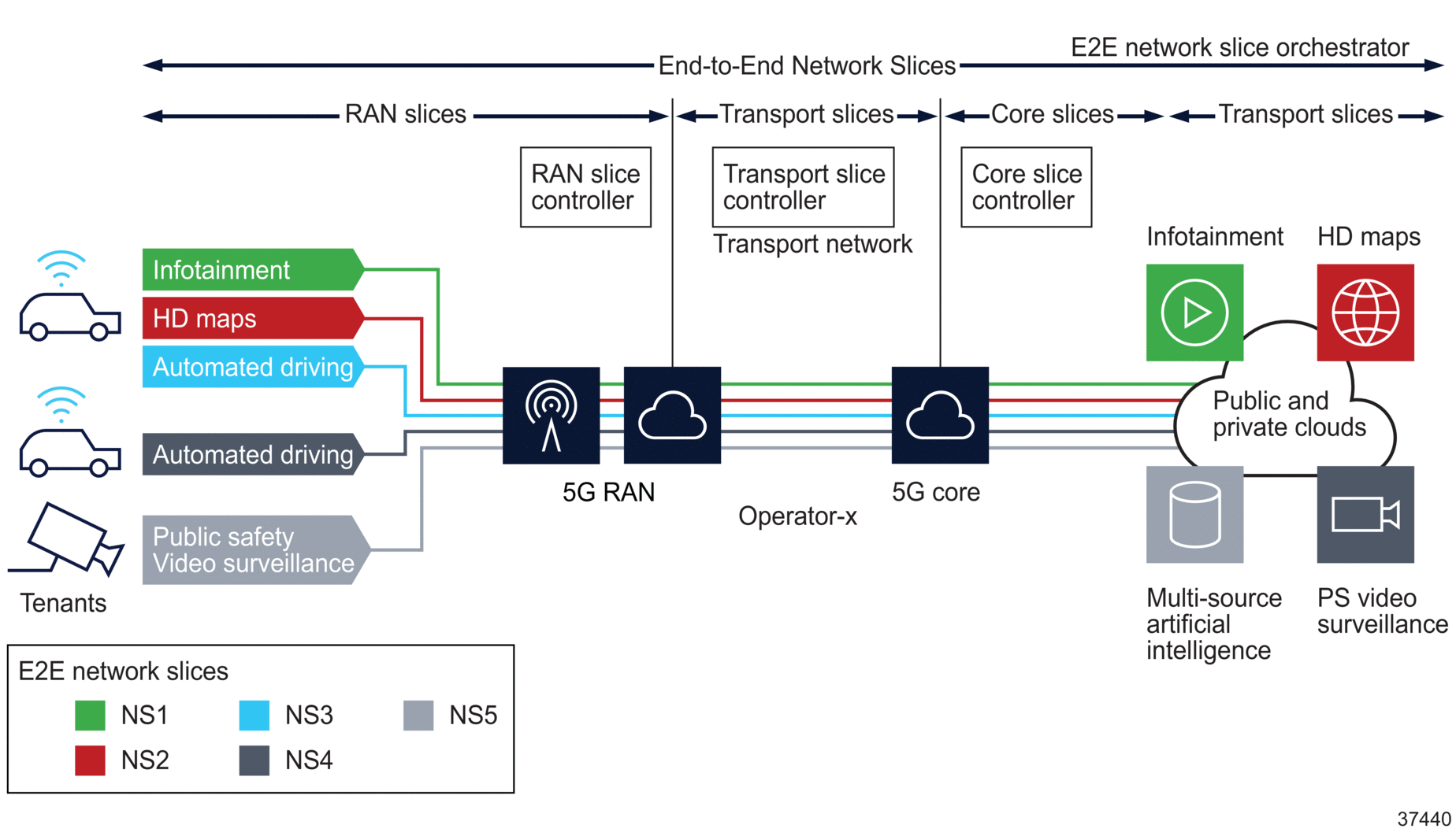
To better demonstrate the concept of network slicing, Figure 1-1, Typical end-to-end network slice from Operator-X perspective shows a typical network from Mobile Network Operator (MNO) Operator-X that supports network slicing. The operator has three customers (a.k.a. tenants): Public Safety, Enterprise-Y, and Enterprise-Z. Each of these customers asks Operator-X to create one or more logical independent end-to-end networks within its common or shared network infrastructure with SLOs. Each of these end-to-end logical networks is called a “network slice”. In this network, Operator-X has created five network slices (NS1 to NS5), each with specific SLO marked in different colors (SLO red, green, etc.).
Network slicing is required since services and devices have their own specific SLO requirements, many of which vary diversely depending on the application. As shown in Figure 1-1, Typical end-to-end network slice from Operator-X perspective, each end-to-end network slice consists of one RAN slice, one Core slice and one or more IETF Network Slices. Note that network slices are inherently an end-to-end concept and used to connect user equipment to tenant-specific applications/servers.
Figure 1-1: Typical end-to-end network slice from Operator-X perspective
In this example network, customer Enterprise-Y has three end-to-end network slices for services “Infotainment”, “HD maps” and “Autonomous driving”, each with its own SLO. Similarly, customers Enterprise-Z and Public Safety each have one end-to-end network slice (NS4 and NS5) for services “Autonomous driving” and “Video Surveillance”, respectively. For instance, NS1 is created by Operator-X for customer Enterprise-Y for service “Infotainment” where the SLO is bandwidth (SLO green) whereas the NS3 is created for the same customer but for “Autonomous driving”, where the SLO is the combination of latency and reliability (SLO blue).
How are network slices created?
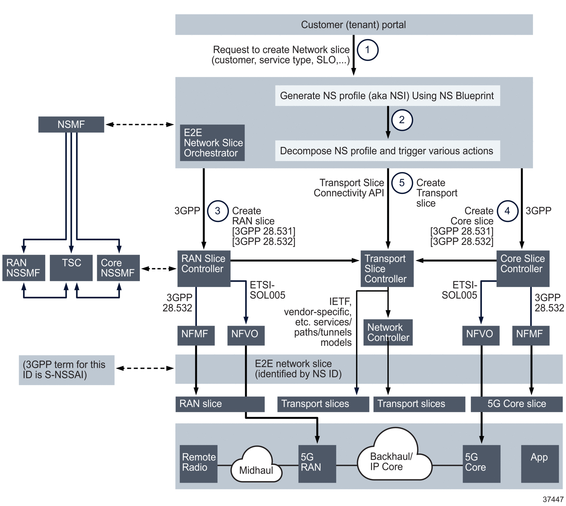
Continuing the example shown in Figure 1-1, Typical end-to-end network slice from Operator-X perspective, the following is an example of how end-to-end network slice NS5 is created in the operator’s network:
-
The “E2E Network slice Orchestrator” receives an abstracted Service Catalog instantiation request from the customer portal.
-
Using Network Slice Blueprints, the “E2E Network slice Orchestrator” creates the “Network Slice Profile (NS Profile)” for this request and starts decomposing the profile request into smaller chunks of network slice subnet sent to various slice domain controllers.
-
The RAN slice controller (i.e. RAN NSSMF) will receive a request to create the RAN Slice. If the RAN is virtualized, it will in turn use the NFVO to initiate VNF creation and then program the RAN slice.
-
Similar to step 3, the Core slice controller (i.e. Core NSSMF) will receive a request to create the Core Slice. If Core is virtualized, it will in turn use the NFVO to initiate VNF creation and then program the Core slice. The Core Slice Controller uses network service descriptors to create new EPC/5GC VNF Components, DC networks, or additional GiLAN SFC VNF Service Chains (e.g. vFW, vNAT, vLoad Balancer).
-
The Transport Slice Controller (i.e. TSC) will act on instructions passed on in the transport slice connectivity API to instantiate various connections between RAN and Core networks, between RAN CU-DU, or RH-DU and Core to applications.
The following figure provides an example for the creation of end-to-end network slice NS5.
Figure 1-2: Network slice creation
Note that Interfaces (3) and (4) are defined in various 3GPP technical specifications such as 28.530, 28.531, 28.540 and 28.541. However, interface (5) currently has no standard. Nokia is working with the IETF and BBF towards standardizing this interface.
What is a transport slice?
Transport slices provide technology-agnostic connectivity between various network physical/virtual functions and applications. The example shown in Figure 1-1, Typical end-to-end network slice from Operator-X perspective displays two transport slices; one transport slice is the connection between the RAN and core slices, and the other is the connection between the core slice and application servers. Each transport slice has its own SLA. IETF network slices have deterministic Service-Level Objectives (SLO) in order to achieve the end-to-end network slice SLA.
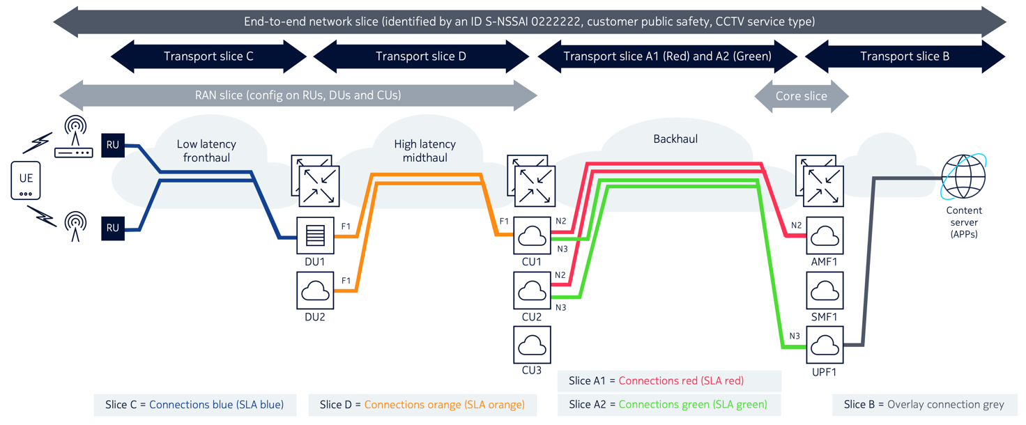
The following figures illustrate the concept of transport slices in various RAN deployments (Distributed-RAN or D-RAN, Centralized RAN and Cloud RAN or C-RAN) for an end-to-end network slice identified by the following attributes:
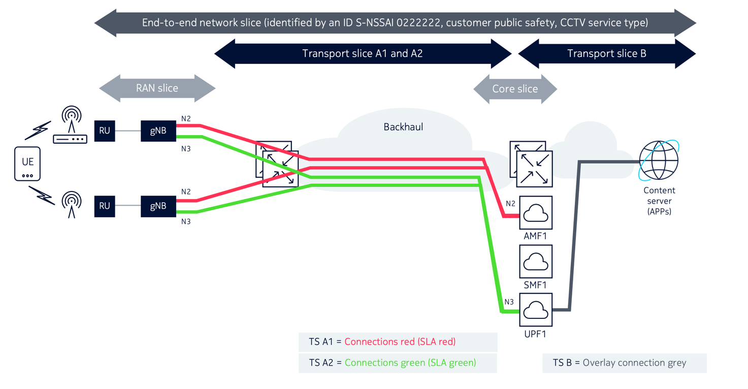
A D-RAN deployment is illustrated in Figure 1-3, Transport slices in Distributed-RAN, where the RAN elements are responsible for all aspects of the radio access functions including signal processing, radio interfacing, and scheduling. This type of deployment is the functional equivalent of the standard 4G network, where eNodeB NEs are responsible for all 4G RAN functions. In this case, the transport slices A1 and A2 are between gNB NEs and core network functions for SLAs Green and Red. The transport slice B (with SLA Grey) is between the core slice and application servers.
Figure 1-3: Transport slices in Distributed-RAN
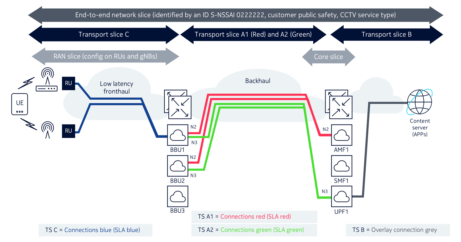
As shown in Figure 1-4, Transport slices in Centralized-RAN, in a Centralized-RAN deployment, the signal processing units (BBU) of the RAN nodes are centralized to simplify network management and enhance computation capability. Resulting from this, a new network type called a “fronthaul network” is introduced to provide the transport connectivity between the Radio Unit (RU) and the BBU. The following figure illustrates the transport slices for this deployment for the same end-to-end network slice.
Figure 1-4: Transport slices in Centralized-RAN
Comparing Figure 1-3, Transport slices in Distributed-RAN and Figure 1-4, Transport slices in Centralized-RAN shows that in addition to transport slices A1, A2, and B, a new transport slice C is required to provide connectivity between the RU NEs and BBU nodes. Transport slice C contains “Blue” connections with strict latency SLA requirements.
In a Cloud-RAN (CRAN) deployment, the BBU NEs can be divided further into Distributed Unit (DU) and Central Unit (CU). In this scenario, a new network called a “midhaul network” is introduced to provide transport connectivity between DUs and CUs. Figure 1-5, Transport slices in Cloud-RAN shows a new slice D with SLA Orange is required to interconnect the DU and CU functions in the midhaul transport network.
