Device-specific commissioning information
7705 SAR management bandwidth
Some additional bandwidth management configuration is required on the NFM-P, if you want to transmit on in-band management on the 7705 SAR. Currently, if in-band and out-of-band management are both used, then the 7705 SAR will only transmit on the out-of-band management out-of-preference if that route exists.
You need to configure NFM-P so that each 7705 SAR with out-of-band management connectivity has the following parameter values:
See To configure polling for a 7250 IXR, 7450 ESS, 7705 SAR, 7750 SR, 7950 XRS, VSR, or Wavence SM for the steps on how to configure these values.
7210 SAS in-band and out-of-band management
The NFM-P supports the in-band and out-of-band management of 7210 SAS NEs, except for the 7210 SAS-D and 7210 SAS-K, which do not support out-of-band management. In-band management uses the system address on a network interface. Out-of-band management uses the management address on the management port. Addresses are assigned using a CLI on the console port; see To commission a device for NFM-P management.
IPv6 is supported for management port addresses on all 7210 SAS chassis types except the 7210 SAS-D, 7210 SAS-K, 7210 SAS-S, and 7210 SAS-Sx. The management port address can be IPv4 or IPv6, but not both.
IPv6 is supported for system interface addresses on the following 7210 SAS chassis types:
Where IPv6 is supported, you can assign a system interface address using IPv4, IPv6, or both. When both IPv4 and IPv6 addresses are assigned, the address used is determined by the Management Protocol parameter configured in To configure a discovery rule.
Note: For 7210 SAS NEs, when both the management address and the system address use only IPv6, the following network functions and protocols are not supported:
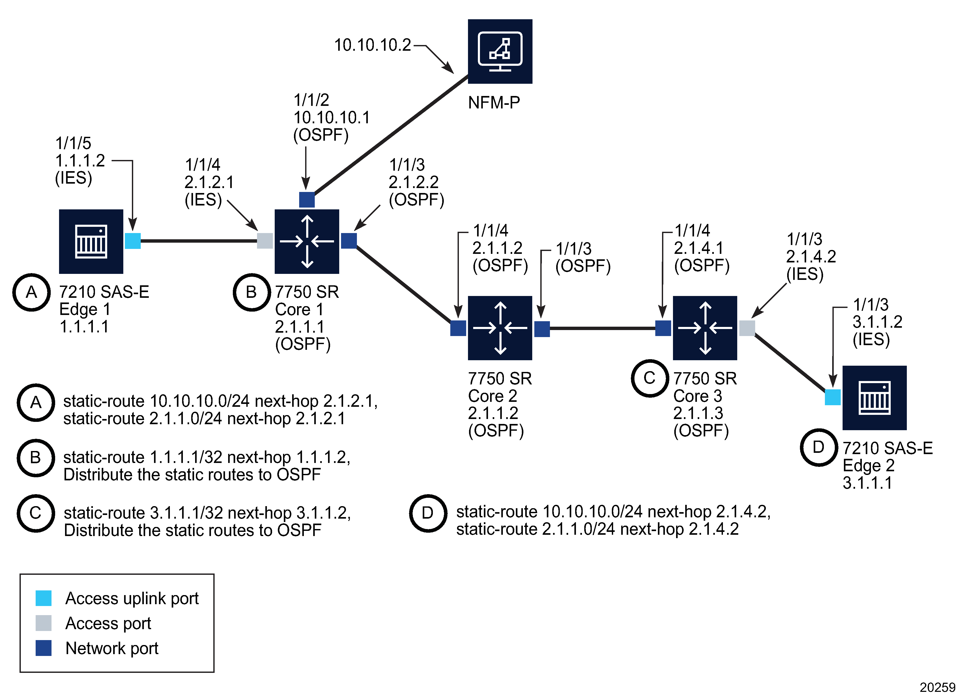
The 7210 SAS-D, 7210 SAS-E, and 7210 SAS-K support static routes, but do not support an IGP or SDPs. The example network shown in the following figure and the associated configuration steps describe the configuration required to enable 7210 SAS-E in-band management using static routes that are distributed to an IGP, which, in the example, is OSPF.
Figure 8-2: Example 7210 SAS-E in-band management network

The following configuration steps are required to set up the example network:
-
Using the CLI, configure the SNMP security parameters on the devices that you need to discover. See To commission a device for NFM-P management for more information.
-
Perform the following steps on Core 1.
-
Configure an interface on port 1/1/2 that connects to the NFM-P server interface.
-
Configure an interface on port 1/1/3, which is connected to Core 2.
-
Create an ASBR OSPF (area 0.0.0.0) instance on the system and enable OSPF on the interfaces to Core 2 and the NFM-P server.
-
Create a routing policy to distribute the static route to OSPF.
-
-
Perform the following steps on Core 2.
-
Perform the following steps on Core 3.
-
Create an L3 interface on port 1/1/4, which is connected to Core 2.
-
Create an L3 interface on port 1/1/3, which is connected to Edge 2.
-
Create an ASBR OSPF (area 0.0.0.0) instance on the system and enable OSPF on the interface to Core 2.
-
Create a routing policy to distribute the static route to OSPF.
-
-
Perform the following steps on Edge 2.
-
Perform the following steps on Edge 1.
-
Ensure that each 7210 SAS-E can ping the network interface IP address which is configured on the NFM-P main server.
-
Ensure that the NFM-P main server can ping the system IP address of each 7210 SAS-E.
-
Configure an in-band polling policy using the NFM-P. See To configure polling for a 7210 SAS for more information.
Model driven devices
Model driven devices are read-only in the NFM-P.