Sample VPLS configuration
Sample VPLS
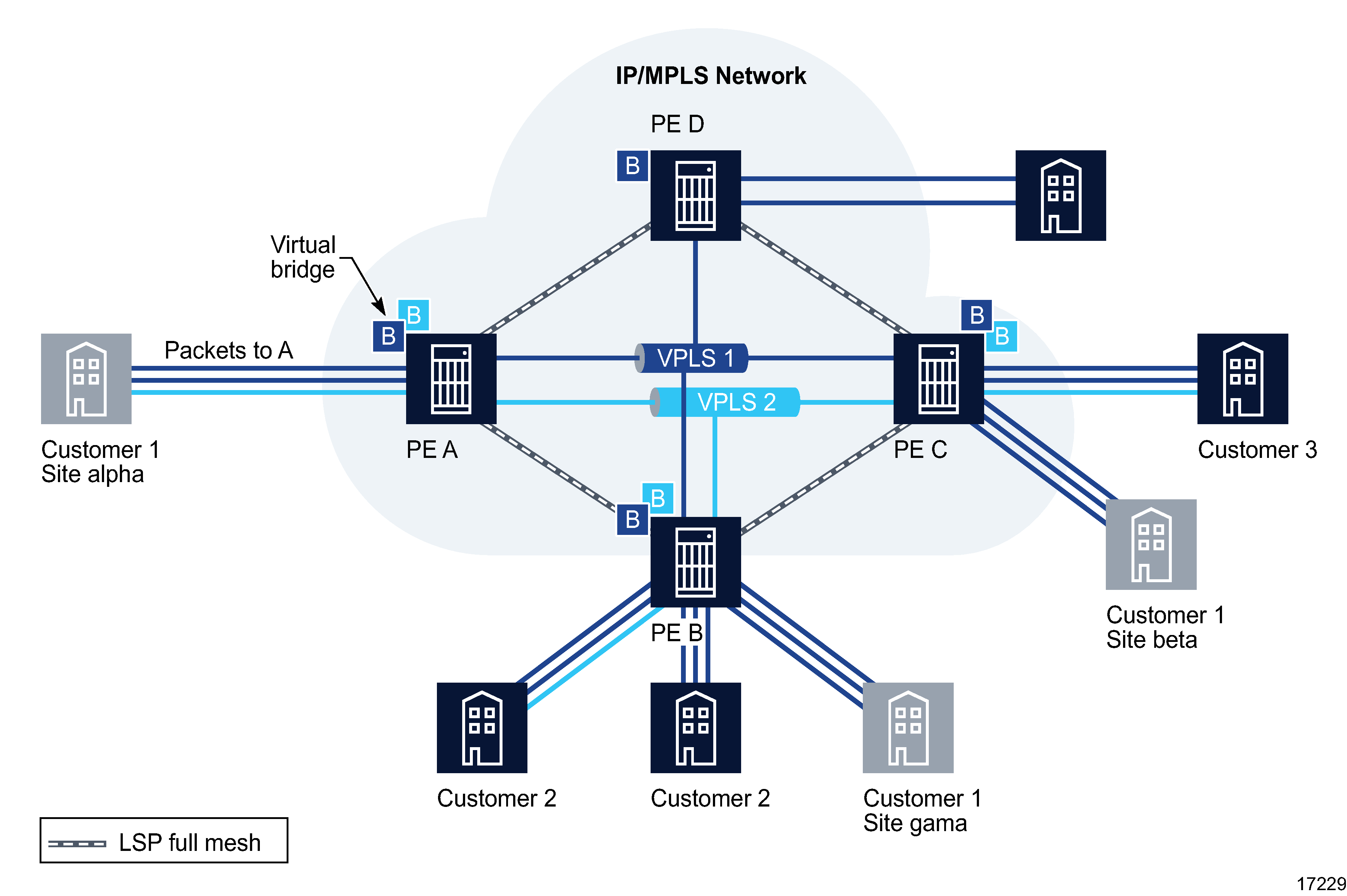
The following figure shows a sample VPLS configuration.
Figure 77-12: Sample VPLS

VPLS 1 is a distributed service, which consists of customer 1 connected to PE A, PE B, and PE C, at sites alpha, gamma, and beta, respectively. All three customer sites belong to VPLS 1.
In the following example, Customer 1 wants to send data from site alpha to site beta.
Customer 1 packets arriving at PE A are associated to the appropriate VPLS 1 for that customer, based on the combination of the access port and the dot1q (VLAN ID) in the packet. PE A learns the source MAC address in the packet and creates an entry in the FIB table that associates the MAC address to the access port on which it was received.
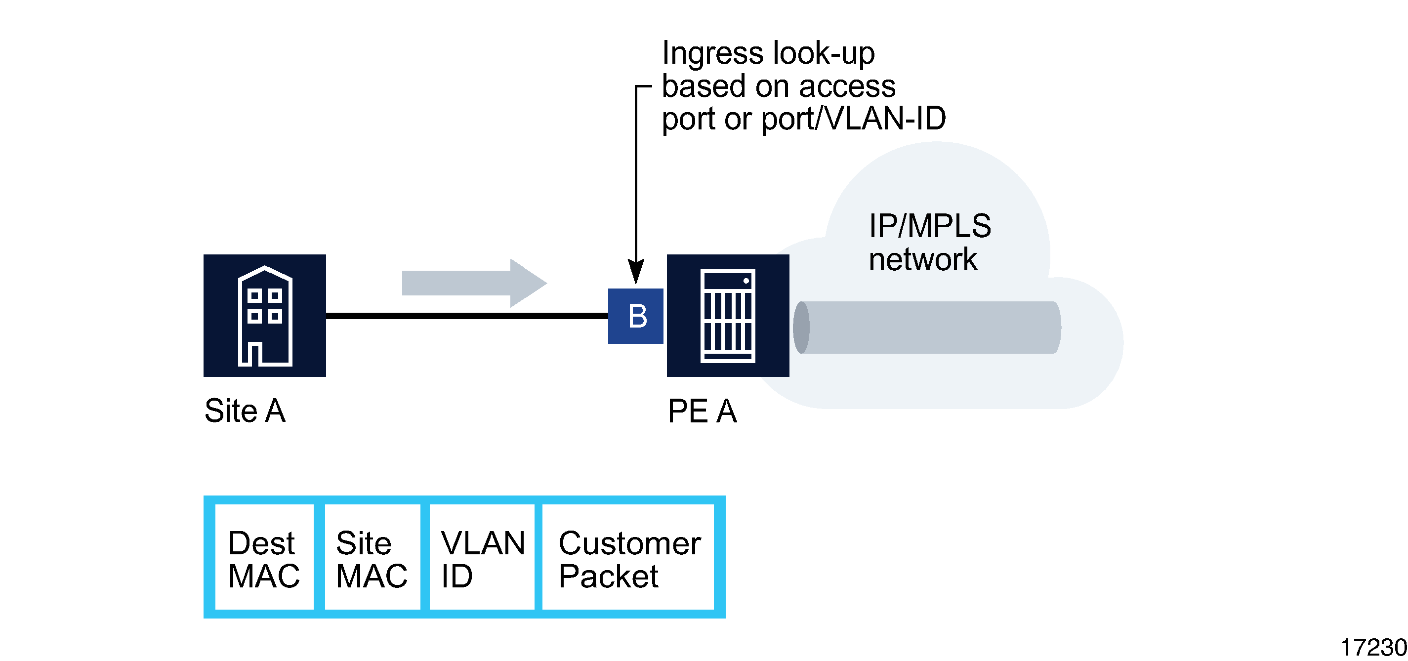
PE A is sending the packets to PE C. The destination MAC address in the packet is looked up in the FIB table of PE A for the VPLS instance, as shown in the following figure.
Figure 77-13: Packet forwarding by ingress router PE A

The destination MAC address in the FIB table has one of two values:
If the destination MAC address is known by PE A, an existing entry in the FIB table identifies the far-end PE C and the service VC label (VLAN ID) used to send the packets from PE A to PE C. PE A chooses a transport LSP to send the packets to PE C. The packets from the customer 1 site alpha to site beta are sent on the LSP after the VC label is removed and the transport label is added to the packet, as shown in Figure 77-13, Packet forwarding by ingress router PE A .
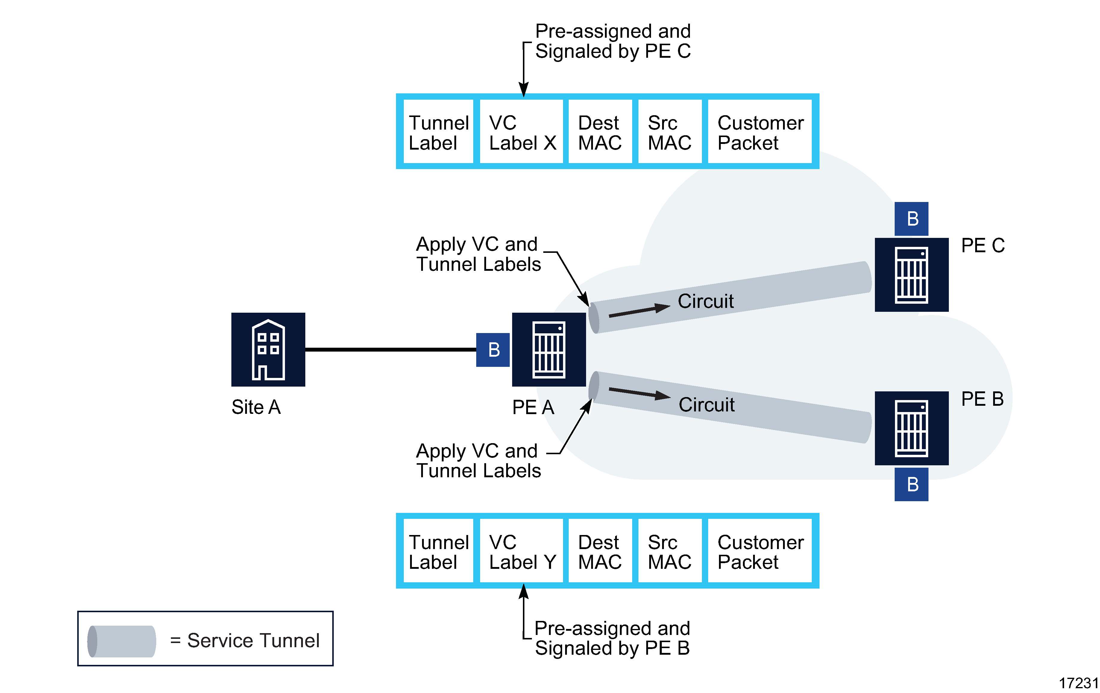
If the destination MAC address is not known by PE A, PE A floods packets to both PE B and PE C, which are both part of VPLS 1. PE A uses the VC labels (VLAN IDs) that PE B and PE C previously signaled for this VPLS 1.
As shown in the following figure , the packets from PE A are transported across the core IP/MPLS network.
Figure 77-14: Packet forwarding from PE A across the core IP/MPLS network

The core routers are LSRs that switch the packets towards their destination based on the tunnel label, also called a transport label. The core routers are not aware that the packets belong to a VPLS.
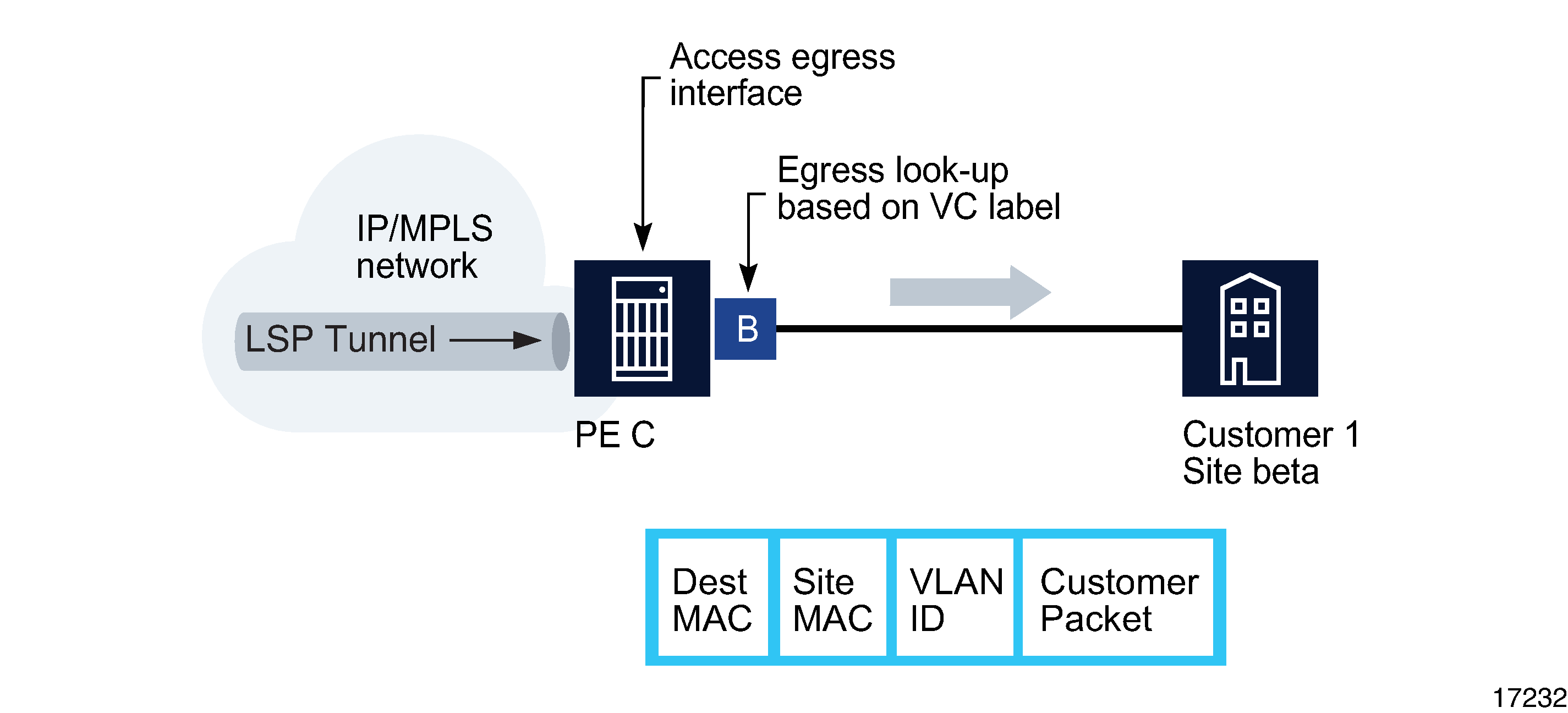
When the packets from PE A arrive at PE C, PE C removes the tunnel label to reveal the VC label that associates the packets with VPLS 1, as shown in the following figure.
Figure 77-15: Packet forwarding by egress router PE C

PE C learns the source MAC address of PE A and creates an entry in its FIB table that associates the MAC address and the VC label with PE A. The destination MAC address is looked up in the FIB table. It has one of two values:
If the destination MAC address is known by PE C, an existing entry in the FIB table identifies the local access (egress SAP) port used by VPLS 1 site beta and the service VC label (VLAN ID) that needs to be added to send the packets from PE C to customer 1.
If the destination MAC address is not known by PE C, PE C floods packets to all local access ports that belong to VPLS 1.
Configuration steps
Assuming the core IP/MPLS network has already been configured, the following high-level tasks are required to configure this sample VPLS.
1 |
Configure policies as required, for example, access ingress and access egress, Scheduler, ACL MAC, Accounting, ANCP, DoS protection, and DDoS protection. |
2 |
Configure ports as access ports for use in the service. |
3 |
Configure service tunnels, as required. |
4 |
Create and configure Customer 1. |
5 |
Create and configure VPLS 1. |
6 |
Create, update, or configure additional sites or L2 access interfaces for the VPLS. |
7 |
For an HVPLS, use spoke SDP bindings to connect VPLS sites to other sites in the same VPLS, to sites in a different VPLS, or to VLL service sites. |
8 |
Create a single MVPLS. |
9 |
Create a composite MVPLS to manage traffic blocking for multiple VPLS. |