lightRadio Wi-Fi
Overview
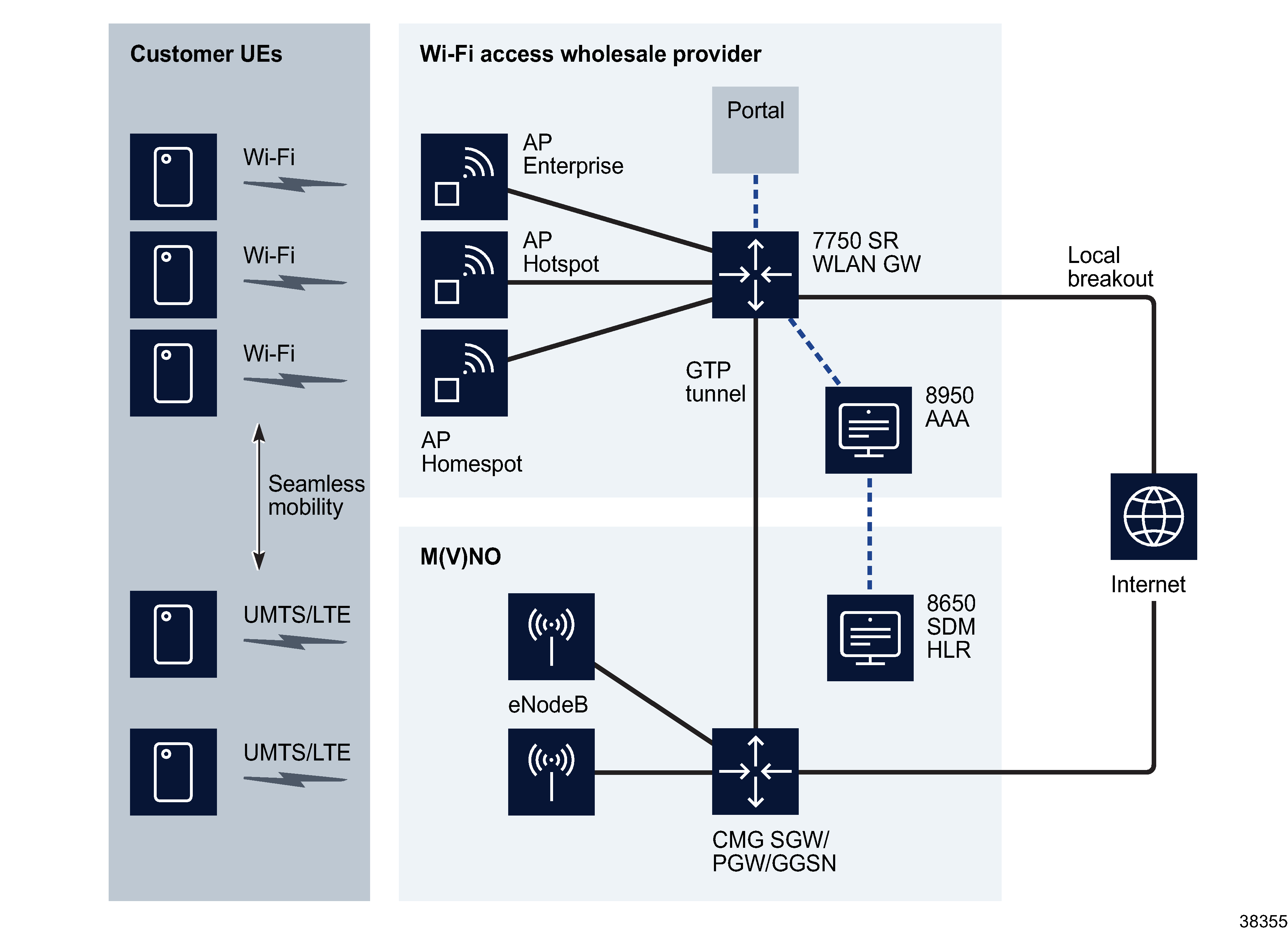
To provide additional capacity and extended coverage to a network, the NFM-P supports the offloading of traffic to WLANs, also known as Wi-Fi Offload. Users within range of a WLAN access point can establish a secure connection using RADIUS authentication. WPA2 keys are provided by a RADIUS server. Data is then transmitted through a single GRE tunnel to the WLAN Gateway (GW), where a subscriber DHCP session is created. The WLAN GW supports a RADIUS proxy server, which stores all available information from the RADIUS access-accept message.
In cases where the RADIUS server instructs the WLAN GW to forward traffic to a GGSN, a mobile gateway (MG) peer is created on the NE. Read-only information relating to the MG peers can be viewed on a base routing instance configuration form, under the WLAN GW tab.
Wi-Fi access can be offered from:
Wi-Fi access can be offered using the following SSID types:
-
Private SSID - used by a residential subscriber to access wireline Internet service.
-
Community SSID - used by visiting subscribers to access a Wi-Fi community broadband service after IEEE 802.1X authentication.
-
Public SSID - used by visiting subscribers to access a free Internet service, or to access a Wi-Fi community broadband service after portal-based authentication.
The following figure shows a typical Wi-Fi Offload scenario. The UE attempts to switch over to Wi-Fi upon detection of a network SSID. Transparent IEEE 802.1X/EAP authentication takes place between the AP and UE. An optional GTP session can be established from the WLAN GW to the GGSN/PGW. This session is established dynamically so that UE traffic can be transferred back to an MMO.
Figure 39-1: Wi-Fi Offload
Migrant user handling
The NFM-P supports migrant user handling in a Wi-Fi offload application. Migrant users may have no intention of using the service, or may be invalid users who have failed authentication on the service. Both of these types of subscriber consume IP addresses and ESM resources on a WLAN GW. In a dormant subscriber handling model, the ESM subscriber is created on the IOM only when the following conditions are met:
-
The subscriber is authenticated, either by RADIUS authentication or by MAC-based pre-authentication (where the RADIUS server remembers a previously authenticated UE).
-
The subscriber is determined to be active by transmitting data beyond the initial DHCP request (data-triggered host creation).
Migrant user support works in conjunction with L2-aware NAT, where each UE is allocated the same inside IP address, and is assigned an outside address based on its subscriber ID (MAC address). In the case of L2-aware NAT and soft GRE, the address is assigned via DHCP, and each user is assigned the same lease. Migrant user handling is configured on an IES or VPRN soft GRE group interface, and includes the following functions:
-
Data-triggered authentication and ESM host creation for ISA users.
-
ESM host creation based on RADIUS COA request for portal-authenticated users.
-
Migrant user DHCP performance.
IP addresses are assigned on the ISA for L2-aware NAT (without ESM host). CPM-based DHCP is employed on a soft-GRE group interface without L2-aware NAT.
An HTTP-redirect function is configured on the ISA.
Distributed subscriber management
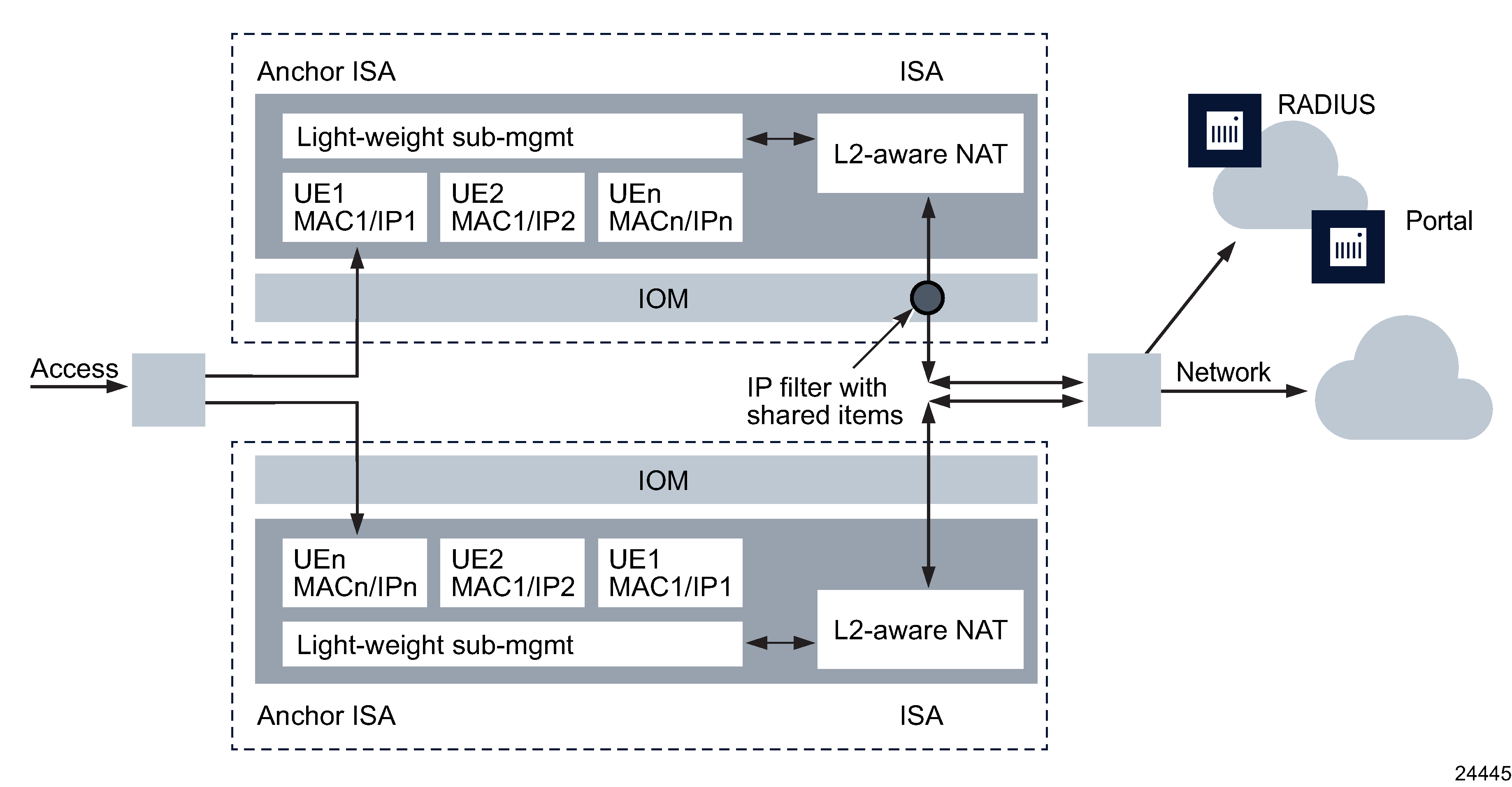
In a distributed subscriber management (DSM) scenario, the subscriber is instantiated as a distributed subscriber on the ISA, based on a RADIUS VSA during initial authentication. DSM works in conjunction with an L2-aware NAT configuration, under which the same inside IP address is allocated to all subscribers on the same group interface (WLAN GW tunnel endpoint), or on the same VLAN tag (corresponding to SSID). Upstream and downstream forwarding is implemented without the need for an ESM host.
The L2-aware NAT is configured on the anchor ISA, and packets do not require an extra pass through the switch fabric. The NAT configuration must include RADIUS accounting.
In a DSM configuration, traffic forwarding is performed without an IOM-based ESM host. Upstream traffic (AP to network) reaches the anchor ISA as usual via B-VPLS. On the anchor ISA, the subscriber state (and L2-aware NAT state) exist prior to DHCP. Downstream traffic (network to AP) passes through L2-aware NAT on the anchor ISA, resulting in an ISA-based subscriber lookup on the anchor ISA, based on the subscriber MAC address. Traffic does not require an additional switch fabric hop to perform the NAT function. Figure 39-2, Distributed subscriber management The following figure shows a DSM configuration.
Figure 39-2: Distributed subscriber management

IPv6 pool manager
In order to support IPv6 migrant users and DSM users, an IPv6 pool manager can be configured on an IES or VPRN subscriber interface. The IPv6 pool manager uses an internal DHCPv6 client to delegate IA_NA or SLAAC prefixes to ISAs. Subnets are added to the FIB with respective ISAs as the next hop, allowing downstream forwarding without an ESM host. Up to eight DHCPv6 servers can be specified on the IPv6 pool manager.
The IPv6 pool manager keeps track of the context in which it allocates subnets in order to correctly acquire subnets after a fail-over or reboot. To support fail-over redundancy of this information, an identical virtual chassis identifier string can be configured on a redundant pair of NEs hosting IPv6 pool managers.
Local breakout using NAT
Typically, Wi-Fi traffic on a WLAN GW is considered GTP-tunneled or local breakout. Traffic is treated as local breakout by default. Local breakout traffic is controlled and routed to the Internet/VPN from the WLAN GW directly.
For certain traffic from a Wi-Fi subscriber, it may be preferable to perform local breakout. This can be performed using the GTP Local Breakout action in the IP filter entries. When this action is applied to traffic marked for GTP-tunneling to the GGSN/PGW, the traffic is routed as local breakout. In this GTP local breakout case, the UE receives its IP address using GTP from the GGSN/PGW, but the matching traffic is routed as local breakout from the WLAN GW directly into the network. This traffic is passed through NAT. NAT is required to ensure the selected traffic is routed back to an IP address on the WLAN GW and not through the GGSN/PGW network. An L2-aware NAT host is created when the address is returned through GTP from the PGW/GGSN. The returned address is the inside IP address. Internally, a GTP tunnel directs traffic to and from L2-aware NAT. Local and remote tunnel endpoint identifiers are create for the local breakout traffic and associated with the ESM host state. For packets that are not sent in the context of a GTP tunnel, this traffic is forwarded.
Hybrid access
In a hybrid access deployment model, the CPE sets up both an LTE and fixed access uplink to the Internet. Both uplinks share the same IP address and classifiers on the CPE, and the PDN gateway determines which link is to be used for traffic. The double uplinks can be used for both redundancy and bandwidth management. AMBR uplink and downlink bit rates are configurable on the mobile gateway/peer profile, along with radio access type. The PDN gateway is configurable for IPv4, IPv6, or Ipv4v6 address requests on the WLAN GW on a base or VPRN routing instance.
VLAN access to anchor ISA
In cases where customers want to employ VLAN access from APs to the WLAN-GW over an L2 network, you can configure L2 APs as part of the WLAN GW configuration on IES and VPRN group interfaces. The NFM-P creates an internal epipe per access SAP or spoke SDP to the WLAN GW tunnel ISA, thereby preserving features requiring soft GRE functionality (for example, migrant user handling and distributed subscriber management). L2 frame processing on WLAN GW ISAs is functionally the same as with a WLAN GW tunnel.
An L2 AP configuration on a WLAN GW specifies an access port, encapsulation information, and an epipe SAP template policy. The epipe SAP template policy allows ingress and egress qos policy configuration and traffic filtering for access SAPs, allowing users to shape traffic based on the Wi-Fi radio technology of the AP.
L2 wholesale
In an L2 wholesale deployment model, subscribers are handled by a wholesale partner (MSO/telco) on behalf of the service provider (retailer), through an L2 network. In this model, the AP is configured with one or more SSIDs per service provider. The wholesaler does not host the subscriber for the service provider. L3 terminations (including address assignment, authentication, and subscriber management information) are performed by individual service providers on their own gateway.
The AP broadcasts an SSID per provider, and is configured with a unique .1q tag per SSID before bridging the L2 frames from the subscriber to the WLAN GW tunnel. VPLS L2 retail service instances are configured statically on the WLAN-GW. Static mappings of .1q tag(s) to L2 retail service instances are configured on the WLAN GW group interface. For each L2 service referenced under a VLAN tag range under the WLAN GW group interface, an internal SAP between the tunnel anchor ISA and IOM is created in that L2 service, on each of the WLAN GW IOMs in the WLAN GW group.
