Service differentiation and QoS
Overview
This TPSDA approach provides a model based on call admission for video and VoIP, with the need to guarantee delay, jitter, and loss characteristics after the service connection is accepted. The architecture also meets the different QoS needs of HSI, namely per-user bandwidth controls, including shaping and policing functions that have little or no value for video and VoIP service delivery.
In conjunction with the architecture's support for content differentiation, this approach enables differentiated service pricing within high-priority data packages, also known as HSI. The distribution of QoS policy and enforcement across BSA and BSR allows the service provider to implement meaningful per-user service level controls. Sophisticated and granular QoS in the BSA allows the service provider to deliver truly differentiated IP services differentiation based on the user as well as on the content.
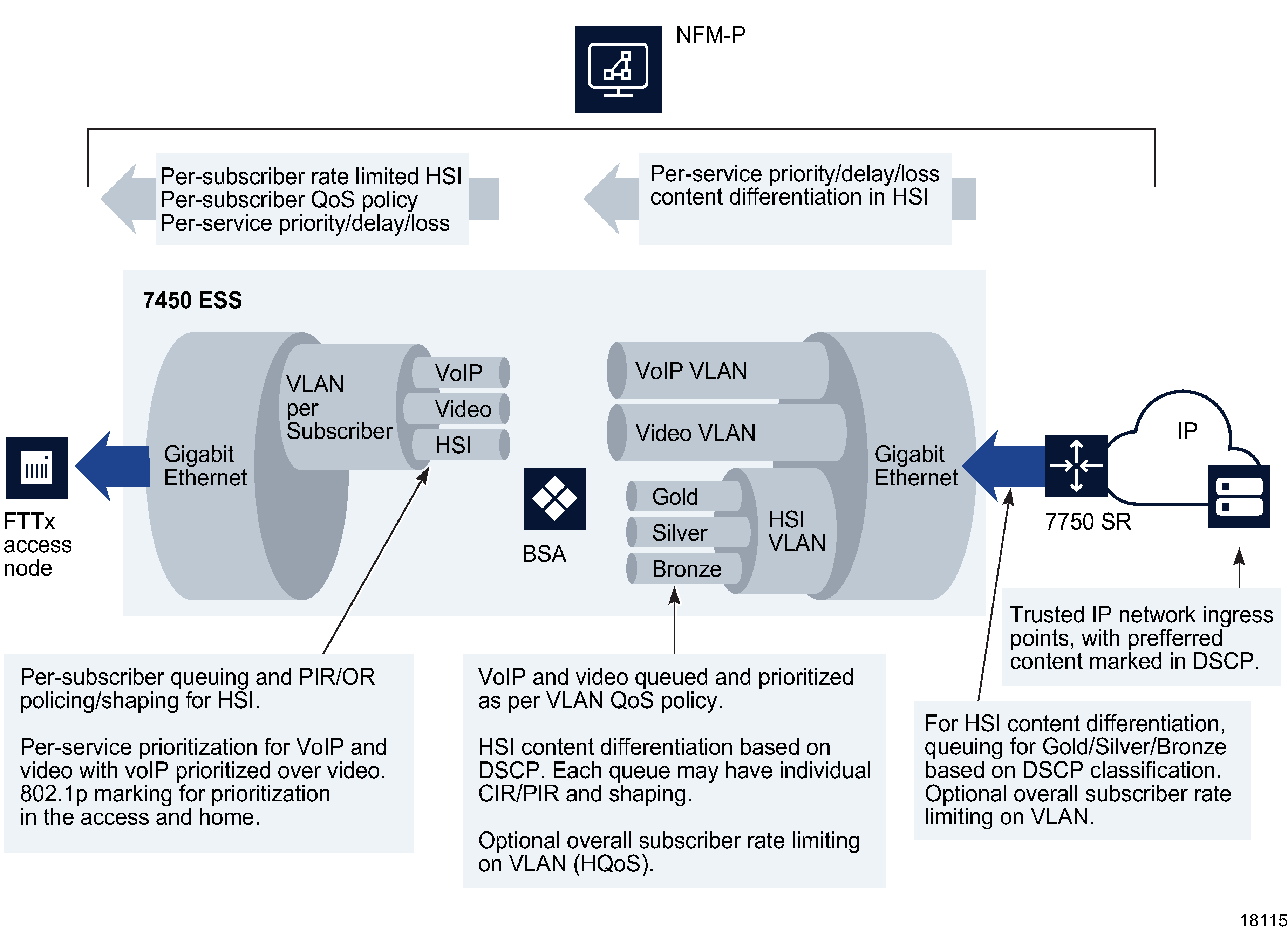
In the BSR to BSA downstream direction, IP services rely on IP layer classification of traffic from the network to queue traffic appropriately towards the BSA. Under extreme loading (only expected to occur under network fault conditions), lower priority data services and/or HSI traffic are compromised to protect video and voice traffic. Classification of HSI traffic based on source network address or IEEE 802.1p marking allows the QoS information to be propagated to upstream or downstream devices.
The BSR performs service distribution routing based on guarantees required to deliver the service and associated content, rather than on individual end users. The BSR only needs to classify content based on its forwarding class for a specific BSA to ensure that traffic for each service receives the appropriate treatment towards the BSA.
Figure 70-14: TPSDA downstream QoS configurations

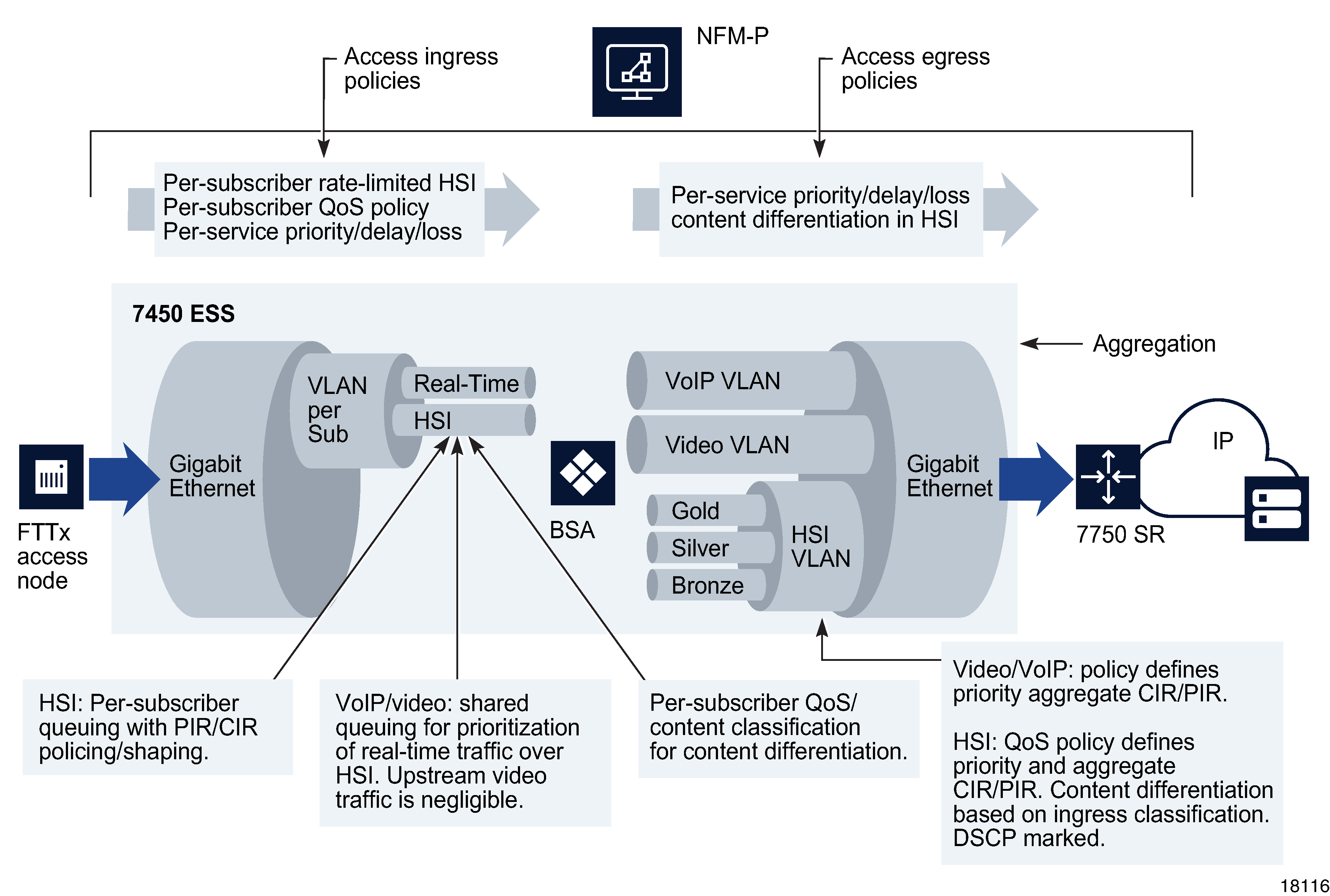
In the BSA-to-BSR upstream direction, traffic levels are substantially lower. Class-based queuing is used on the BSA network interface to ensure that video traffic is forwarded with minimal delay and that preferred data or HSI high-priority data traffic services receive better treatment than for best-effort Internet traffic. The IP edge device (BSR) therefore does not need to enforce per-user policies for hundreds of thousands of users. This function is distributed to the BSAs, and the per-user policies can be implemented on the interfaces directly facing the access NEs.
The BSA is capable of scheduling and queuing functions on a per-service, per-user basis, in addition to performing wire-speed packet classification and filtering based on both L2 and L3 interfaces. In addition to per-service rate limiting for Internet services, service traffic for each user can be rate-limited as an aggregate using a bundled service policy created using the NFM-P. These functions allow different users to receive different service levels independently and simultaneously.
Figure 70-15: TPSDA upstream QoS configurations

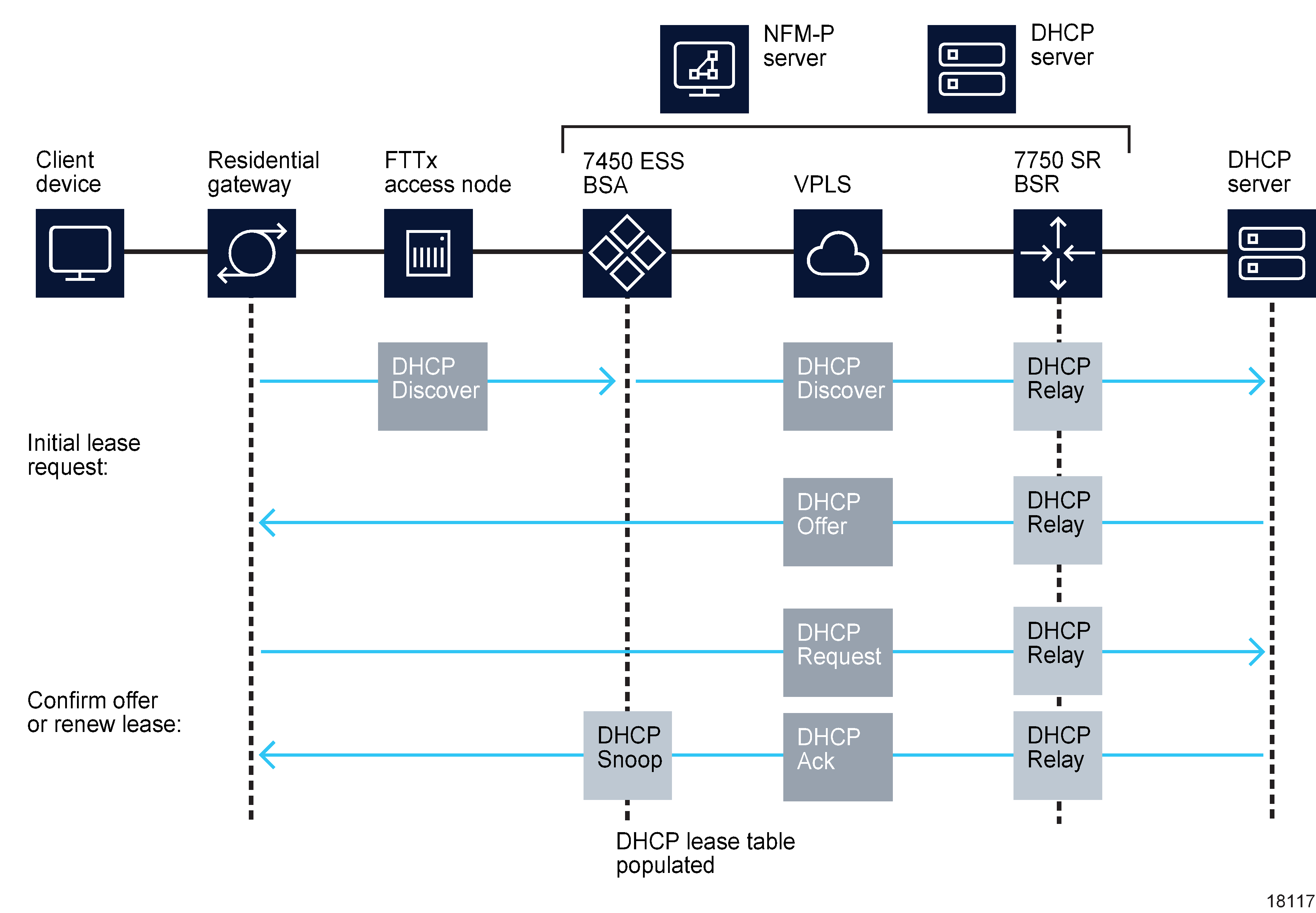
When a residential host device such as a residential gateway or a set-top box in the customer's home starts up, it requests network information, including the required IP address from a DHCP server. The figure below shows IP address assignment. See Table 70-4, TPSDA features for information about DHCP configuration options in the TPSDA.
Figure 70-16: DHCP IP address assignment in the TPSDA

The table below lists the TPSDA features that you can configure using the NFM-P.
Table 70-4: TPSDA features
|
Feature and use |
Notes |
Reference |
|---|---|---|
|
Split horizon groups | ||
|
For the TPSDA, there can be no user-to-user communication in the BSA; instead, all communication is done through the BSR. This residential bridging is done using split horizon groups, which ensures that traffic from different SAPs in the same service are not forwarded to other SAPs or spokes. |
Traffic arriving on a spoke service tunnel or SAP within the split horizon group is not copied to other SAPs or spoke service tunnels. Traffic is copied to SAPs and spokes in other split horizon groups existing within the same service, such as a VPLS. |
See Chapter 77, VPLS management for configuration of split horizon groups. |
|
DHCP | ||
|
For the TPSDA, host devices, such as a residential gateway, SIP phone, or set-top box, use DHCP to obtain IP address and other network configuration information. The client device sends a DHCP discover message to request an IP address. The sequence of events is shown in Figure 70-16, DHCP IP address assignment in the TPSDA . |
Information added to the DHCP discover requests may include information added by the FTTx access NE or the BSA, for example, the shelf, slot, port, VPI, VCI, or other identifier of the host. You can use the NFM-P to configure DHCP relay on the first IP interface in the upstream direction. The BSA or BSR relays the message to a DHCP server. The gateway (residential gateway) IP address indicates to the DHCP server the subnet an IP address should be allocated to for the host. |
See the appropriate service configuration chapter, as DHCP, option 82, and DHCP relay are configured at the service level. |
|
DHCP relay DHCP discover messages are broadcast packets that typically do not leave the IP subnet. DHCP relay agents intercept the requests and forward them as unicast messages to a DHCP server. DHCP request messages from subscriber hosts are usually sent from the FTTx access NE, with information appended to uniquely identify the residential gateway, either by MAC address of the residential gateway or by an option 82 string identifier that indicates the device, port type, rack, shelf, slot, port, and VLAN ID or VPI/VCI of the circuit connected to the residential gateway. |
The DHCP relay agent sets the GIADDR in the packet to the IP address of the ingress interface (SAP). You must configure the BSA and BSR devices as DHCP relay agents when the DHCP requests are going to be forwarded to a DHCP server. The maximum DHCP relay packet size is 1500 bytes. |
See the appropriate L3 service (IES and VPRN) or L2 service (VPLS) configuration chapter. |
|
DHCP lease state table The BSA maintains the identities of hosts that are allowed network access for each SAP on each service. |
The lease state information is collected by snooping DHCP acknowledge messages on the SAP, using DHCP snooping. Entries in the DHCP lease state table remain valid for the duration of the IP address lease. |
|
|
DHCP snooping The BSA can copy DHCP packets and inspect them to help secure the system. For example, if malicious user A sends an IP packet requesting a video stream intended for user B, return packets sent to user B could jam B’s connection. |
Use the NFM-P to configure DHCP snooping for the following purposes:
|
See the appropriate service chapters for configuration of the lease populate and snooping parameters. See Chapter 74, Residential subscriber management for information about using DHCP snooping for subscriber identification purposes. |
|
Option 82 The DHCP relay option allows managed devices to append information to the DHCP request that identifies where the DHCP request originated. You can also independently insert Option 82 information when DHCP snooping is enabled on a VPLS SAP. The Option 82 information can be:
|
Using Option 82, you can identify:
The maximum DHCP relay packet size is 1500 bytes. If adding Option 82 information to the packet causes the packet to exceed 1500 bytes, the DHCP relay request is forwarded without including the Option 82 information. |
See the appropriate service configuration chapter. For DHCP option 82 information inserted to identify subscribers, see Chapter 74, Residential subscriber management . |