VLL service management overview
VLL types
The NFM-P supports the creation of the following VLL service types:
See the NSP NFM-P Microwave Radio User Guide for Wavence device VLAN service management configuration information.
Epipe (Ethernet VLL)
An Epipe, or Ethernet VLL service, provides a point-to-point Ethernet service. One endpoint of an Epipe uses Ethernet encapsulation, and the other endpoint uses Ethernet, ATM, frame relay, or CEM encapsulation. An Epipe effectively provides ATM and frame relay bridged encapsulation termination for interworking. The NFM-P supports local cross-connecting when the Epipe endpoints are on the same device.
The device supports these Epipe connectivity scenarios:
-
a frame relay or ATM user in an ATM network communicating with an Ethernet user on an IP/MPLS network
-
a frame relay or ATM user who connects to a PE device in an IP/MPLS network and communicates with an Ethernet user who connects to another PE device in the same network
ATM users connect through a UNI using AAL-5 or bridged Ethernet PDUs, and use the VCI/VPI as the ATM SAP identifier. Frame relay users connect through a UNI that uses Multiprotocol Interconnect over frame relay or bridged Ethernet PDUs, or over an Ethernet UNI interface. The DLCI is the frame relay SAP identifier. The VCI/VPI and DLCI identifier tags are transparent to the service and remain unaffected during transport.
Devices which support MEF 8 can support TDM services encapsulated on Epipe services using circuit emulation mode. A SAP with a TDM port can then be assigned to an Epipe service using CEM encapsulation. The TDM SAP defines a local and remote ECID as well as a remote MAC address. The MAC address of the TDM port is used as the source MAC address for the emulated circuit.
MEF 8 can be configured on an Epipe service in the following two scenarios:
Using MEF 8 functionality to emulate TDM services, Epipe services can interoperate with devices that support MEF 8 Epipe services, but not MPLS Cpipe services, such as the Wavence SM. MEF 8 is supported on the 7450 ESS, 7705 SAR, and 7750 SR.
The NFM-P supports the following Ethernet SAP encapsulations for an Epipe service:
Epipe services allow you to designate a dot1q encapsulated SAP as the default SAP for a specific port. For more information about how you can use default SAPs on an Ethernet port, see Default SAPs in VPLS management overview .
A default SAP can co-exist with other SAPs on a port, but it cannot be implemented on a null encapsulated port. You can use the NFM-P GUI to create a default SAP by specifying an outer encapsulation value of 4095 or * for a SAP. If the XML API is used, the outer encapsulation value is always 4095.
When you enable the Enable Q in Q Untagged Sap parameter on an NE, the NFM-P allows the creation of the following two default SAP types:
-
The SAP type *.null functions as a default SAP for single-tagged frames on a Q in Q port. This SAP accepts single tags in the range 0 to 4095 as well as untagged traffic.
-
The SAP type *.* functions as a default SAP for double-tagged frames on a Q in Q port. This SAP accepts untagged, single-tagged, and double-tagged frames with tags in the range 0 to 4095.
SAP types X.0 and X.* as well as SAP types *.null and *.* can be configured on the same Q in Q port on an Epipe service.
QTag Manipulation
The NFM-P supports QTag Manipulation on VLL access interfaces, on supporting NEs. QTag Manipulation allows you to define actions for inner and outer VLAN IDs, and assign tag values where required. For example, you can configure QinQ Tunneling, VLAN Translation, or other manipulations for L2 traffic that ingresses and egresses the interface. QTag Manipulation is configured on the Port tab of the L2 Access Interface properties form. See the NE documentation for more information about QTag Manipulation actions.
3-plus-tag Epipe service
You can configure a 3-plus-tag Epipe service on supporting 7210 SAS NEs. A 3-plus-tag Epipe service enables processing of packets with more than two tags when received on a QinQ SAP. A 3-plus-tag Epipe service requires a QinQ SAP as one endpoint and one of the following as the other endpoint:
The spoke SDP binding must be of VC type VLAN, and the encapsulation values, or tags, must be configured to match. See To configure a VLL site , To configure a spoke SDP binding on a VLL site , To create a VLL L2 access interface on a terminating site , and the NE documentation for more information.
Support for 3-plus-tag Epipe services on 7210 SAS NEs varies, depending on the chassis type and release. See the NE documentation for support information.
Ethernet CFM is supported for 3-plus-tag Epipe services.
Apipe (ATM VLL)
An Apipe, or ATM VLL service, provides a point-to-point ATM service between users who connect to 7750 SR, 7705 SAR, 7950 XRS, or 7450 ESS NEs in an IP/MPLS network directly or through an ATM access network. One endpoint of an Apipe uses ATM encapsulation and the other endpoint uses ATM or frame relay encapsulation. An ATM PVC—for example, a VC or a VP—is configured on the managed device. As a result, the ATM switches at the service endpoints appear to be directly connected over an ATM link. The NFM-P supports VPI/VCI translation in an Apipe and supports local cross-connecting when the Apipe endpoints are on the same managed device.
An Apipe encapsulates standard UNI/NNI cells that ingress the ATM SAP into a pseudowire packet using N:1 cell mode encapsulation or AAL-5 SDU mode encapsulation. When using N:1 cell mode encapsulation, an Apipe supports cell concatenation into a pseudowire packet and the setup of both VC- and VP-level connections.
For ATM and frame relay interworking, an Apipe provides a point-to-point service between a user who connects to an existing ATM network and another user who connects to a PE in an IP/MPLS network. An ATM AAL-5 SDU pseudowire or a frame relay 1-to-1 mode pseudowire connects the nodes. The PE performs an FRF.5 interworking function to join the ingress and egress data paths.
An ATM VT SAP on a PE is identified by the physical port and VPI range. Cells that arrive on a specified port and are within the specified VPI range go into a single pseudowire for transport through the IP/MPLS network. A user can configure the whole ATM port as a VT and does not need to specify a VPI range. There is no ingress or egress VPI/VCI translation or loss of cell order.
The 7705 SAR uses N>1 cell mode encapsulation to support multiple VCs on an Apipe. You can multiplex VCs on a 7705 SAR Apipe service using SAP aggregation groups. See To create a SAP aggregation group on a 7705 SAR Apipe for more information about how to configure SAP aggregation groups.
The NFM-P supports the ATM N:1-N>1 VC type to allow interoperability between 7705 SAR and 7750 SR Apipe services, despite each site using different cell mode encapsulation. An interoperating Apipe service uses the ATM N:1-N>1 VC type, while the 7705 SAR site uses ATM VCC and the 7750 SR uses ATM Cell. An interoperating Apipe service combines SAP aggregation groups from the 7705 SAR Apipe with connection profiles from the 7750 SR Apipe onto a single Apipe service. See Chapter 63, Connection profile policies for more information about connection profiles.
Fpipe (frame relay VLL)
An Fpipe, or frame relay VLL service, provides a point-to-point frame relay service between users who connect to PE 7750 SR or 7450 ESS NEs in an IP/MPLS network. Both endpoints of an Fpipe use frame relay encapsulation. An Fpipe connects users through frame relay PVCs. An Fpipe receives standard Q.922 core frames on the frame relay SAP and encapsulates them in a pseudowire packet according to the 1-to-1 frame relay encapsulation mode. This is the VC type used on the SDP by default. The NFM-P does not support the many-to-one, or port encapsulation, mode. Fpipe creation supports local cross-connecting when the endpoints are on the same managed device.
Hpipe (HDLC VLL)
An Hpipe, or HDLC VLL service, is used to carry HDLC PDUs over an MPLS network. HDLC PWs enable service providers to offer emulated HDLC services over existing MPLS networks. HDLC mode provides port-to-port transport of HDLC-encapsulated traffic.The HDLC PDU is transported in its entirety, including the HDLC address and control fields, but the HDLC flags and the FCS are excluded. If the optional control word is used, the flag bits in the control word are not used and must be set to 0 for transmitting and must be ignored upon receipt.
Before HDLC SAPs can be configured, the mda-mode command must be set to cem-fr-hdlc-ppp at the card level. Only ports that are configured with HDLC encapsulation can be mapped to an Hpipe SAP.HDLC encapsulating ports do not terminate the HDLC. The ports pass the HDLC frames through the Hpipe. HDLC encapsulated ports can pass through any HDLC-framed traffic, such as Cisco-HDLC, FR, PPP, etc.
Ipipe (IP interworking VLL)
An Ipipe, or IP interworking VLL service, uses the IP/MPLS network to provide Layer 3 connectivity between different Layer 2 technologies. An Ipipe service provides point-to-point IP connectivity between a user on a frame relay, ATM, cHDLC, or PPP access circuit with routed PDU IPv4 encapsulation and a user on an Ethernet interface. The Ethernet SAP interface can terminate on a 7705 SAR, 7750 SR, 7450 ESS, or 7950 XRS.
The following table summarizes the supported SAP types.
Table 76-1: Supported SAP types
|
SAP Types |
Frame relay |
ATM |
PPP/IPCP |
cHDLC |
Ethernet |
|---|---|---|---|---|---|
|
Frame relay |
✓ | ||||
|
ATM |
✓ | ||||
|
PPP/IPCP |
✓ |
✓ | |||
|
cHDLC |
✓ |
✓ | |||
|
Ethernet |
✓ |
✓ |
✓ |
✓ |
✓ |
In an Ipipe service, both CE devices appear to be on the same IP interface. The PE devices must therefore resolve Layer 2 addresses when different resolution protocols are used on either SAP. Each PE device is manually configured with the IP addresses of both CE devices, or alternatively, can be set to automatically discover the IP addresses of the CE routers. The PE device maintains an ARP cache context for each IP interworking VLL, and responds to ARP request messages received on the Ethernet SAP. The PE device responds with the Ethernet SAP configured MAC address as a proxy for an ARP request for the frame relay, ATM, or PPP user access circuit IP address, and silently discards any ARP request message received on the Ethernet SAP for any other address. The PE device maintains a record of the association of IP addresses with MAC addresses for ARP requests that it receives over the Ethernet SAP.
An Ipipe SAP can be bound to a physical or logical port with PPP, cHDLC, ATM, or FR encapsulation. ATM users connect through a UNI using AAL-5 MUX IP or AAL-5 SNAP routed PDU encapsulation. Frame relay users connect using routed PDU IPv4 encapsulation. PPP interfaces use PPP/IPCP encapsulation of an IPv4 packet. Users of cHDLC connect using routed IPv4 encapsulation.
The NFM-P supports the following Ethernet SAP encapsulations for an Ipipe service:
Note: IPCP SAPs on the 7705 SAR can be configured to assign primary and secondary DNS addresses to the remote peer.
The following identifiers are used for packet forwarding:
Cpipe (circuit emulation VLL)
A Cpipe, or circuit emulation VLL service, provides a point-to-point CEM service between supporting devices. The endpoints of a Cpipe use CEM encapsulation.
The Cpipe L2 access interface can be bound to a unstructured DS1 or E1 channel, a channelized DS0 channel group, or a DS0 group with CAS signaling. Consider the following when creating a Cpipe:
VLL spoke switching
VLL spoke switching allows you to create a VLL service by cross-connecting two spoke SDPs. Spoke switching allows you to scale L2 services, such as VLLs and H-VPLS, over a multi-area network without the requirement for a full mesh T-LDP. The NFM-P supports spoke switching on all VLL types, however, all service instances must be the same type.
The NFM-P supports VLL services with spoke switching on the 7210 SAS, 7250 IXR, 7450 ESS, 7750 SR, and 7950 XRS. Support for 7210 SAS NEs varies depending on the chassis type and release; see the NE documentation for information.
The following table describes the VLL site types that you can use in a spoke switching configuration.
Table 76-2: VLL site types
|
VLL site type |
Description |
|---|---|
|
Terminating |
VLL instance has one or two VLL SAPs. |
|
Switching |
VLL instance cross-connects two spoke bindings. |
The following figure shows a switching VLL that connects two VPLS. The configuration uses two T-PEs, three S-PEs, and two pairs of spoke bindings to connect the two VPLS.
Figure 76-1: VLL spoke switching
Configuration requirements
You must consider the following configuration rules when provisioning VLL services with spoke switching:
-
Segments in the service can run on different types of tunnels; for example, LDP, GRE, and RSVP SDPs.
-
VLL instances in a service must use the same service ID to avoid the discovery of multiple and composite services.
-
VLL with one or more switching sites must have two or more terminating sites.
-
Autobinding creation service is not supported for switching VLLs.
VLL redundancy
VLL redundancy requires that you associate the SAP or SDP bindings to an endpoint. You can configure the endpoint association as active or standby so that you can create a redundant configuration. The associated nodes use signaling to determine the active SAP or SDP binding. The NFM-P supports VLL redundancy on SR OS NEs.
A VLL service site can have up to two local endpoints. A local endpoint combines a SAP with a binding (access) or a group of bindings (network). A SAP or an SDP binding can also exist without an endpoint association.
The 7450 ESS, 7750 SR, and 7950 XRS support HSDPA offload fallback for VLL Apipe and Epipe services by allowing fallback from an active PW on a primary spoke SDP to a secondary SAP.
The following table describes the components in redundant VLL configurations.
Table 76-3: VLL components for redundant configurations
|
VLL component |
Description |
|---|---|
|
Primary or Redundant binding |
Primary or redundant binding is the same as a regular spoke binding. Up to four spoke bindings can form a VLL instance network endpoint. Only one binding can be configured as the primary; up to 3 others can only be configured as redundant spokes. Each redundant spoke has a precedence value to decide which spoke is the immediate backup. Only the terminating VLL instance can have multiple bindings on the network side endpoint. A switching VLL instance has up to 2 bindings, one on each side. |
|
Inter-Chassis Backup |
You can use an ICB in conjunction with a redundant SAP to provide protection for the SAP. The SAP must also be associated with a MC-LAG or MC-APS port. The ICB transports network traffic to the SAP on the second PE when the local SAP is unavailable. You must define a switching state for the redundant SAP. You must also configure the return ICB on the opposite endpoint of the protected site. |
Configuration options
The following table describes the redundancy configuration options for each VLL site.
Table 76-4: VLL redundancy configuration options
|
Option |
Configuration |
Description |
|---|---|---|
|
1 |
SAP SDP binding |
You can create an endpoint without any SAP or SDP. |
|
2 |
SAP SAP |
You can create an endpoint without any SAP or SDP. |
|
3 |
SDP binding SDP binding |
You can configure this option for switching sites only. |
|
4 |
SAP Endpoint with SDP bindings (maximum of 4 spokes and 1 ICB) |
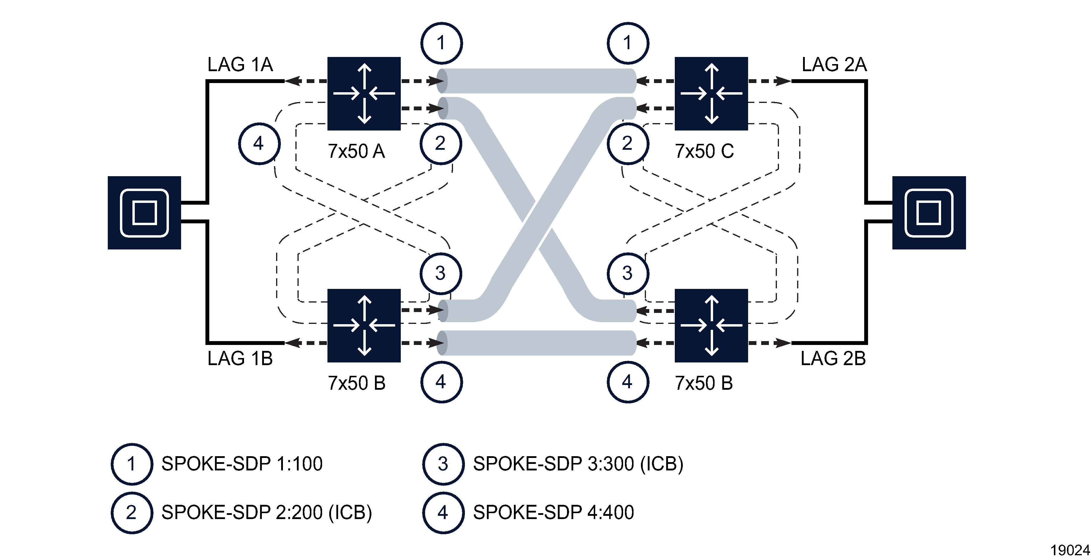
Figure 76-2, VLL redundancy configuration - option 4 shows the configuration of this option on the PE nodes. |
|
5 |
Endpoint with SAP/ICB SDP binding |
Figure 76-3, VLL redundancy configuration - option 5 shows the configuration of this option on Node B. |
|
6 |
Endpoint with SAP/ICB endpoint with SAP/ICB |
Figure 76-4, VLL redundancy configuration - option 6 shows the configuration of this option. |
|
7 |
Endpoint with SAP/ICB Endpoint with up to 4 SDP bindings |
Figure 76-5, VLL redundancy configuration - option 7 shows the configuration of this option. |
Figure 76-2: VLL redundancy configuration - option 4
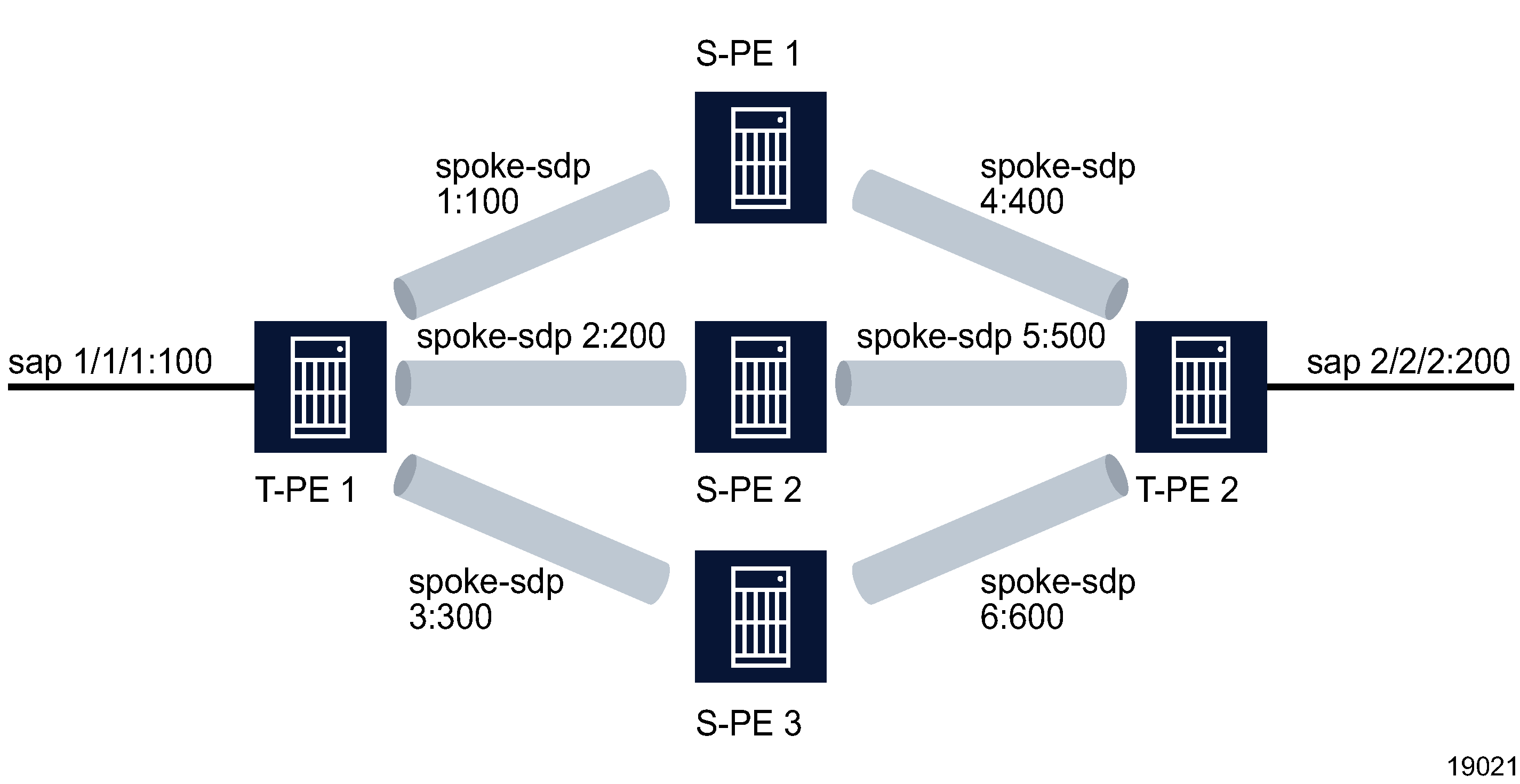
Figure 76-3: VLL redundancy configuration - option 5
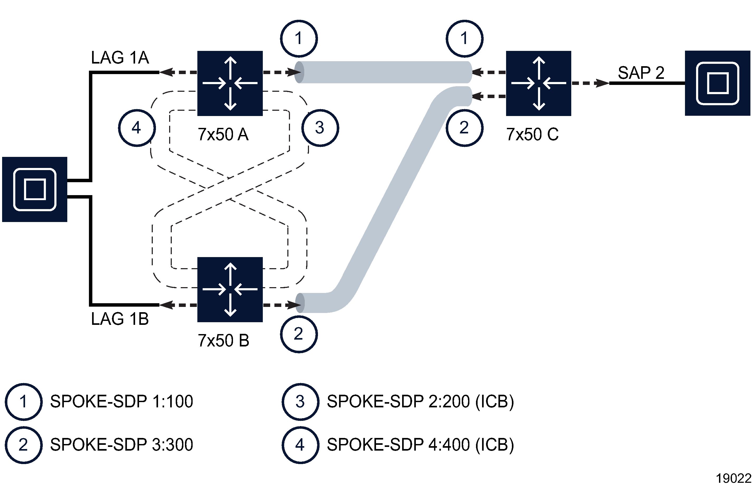
Figure 76-4: VLL redundancy configuration - option 6
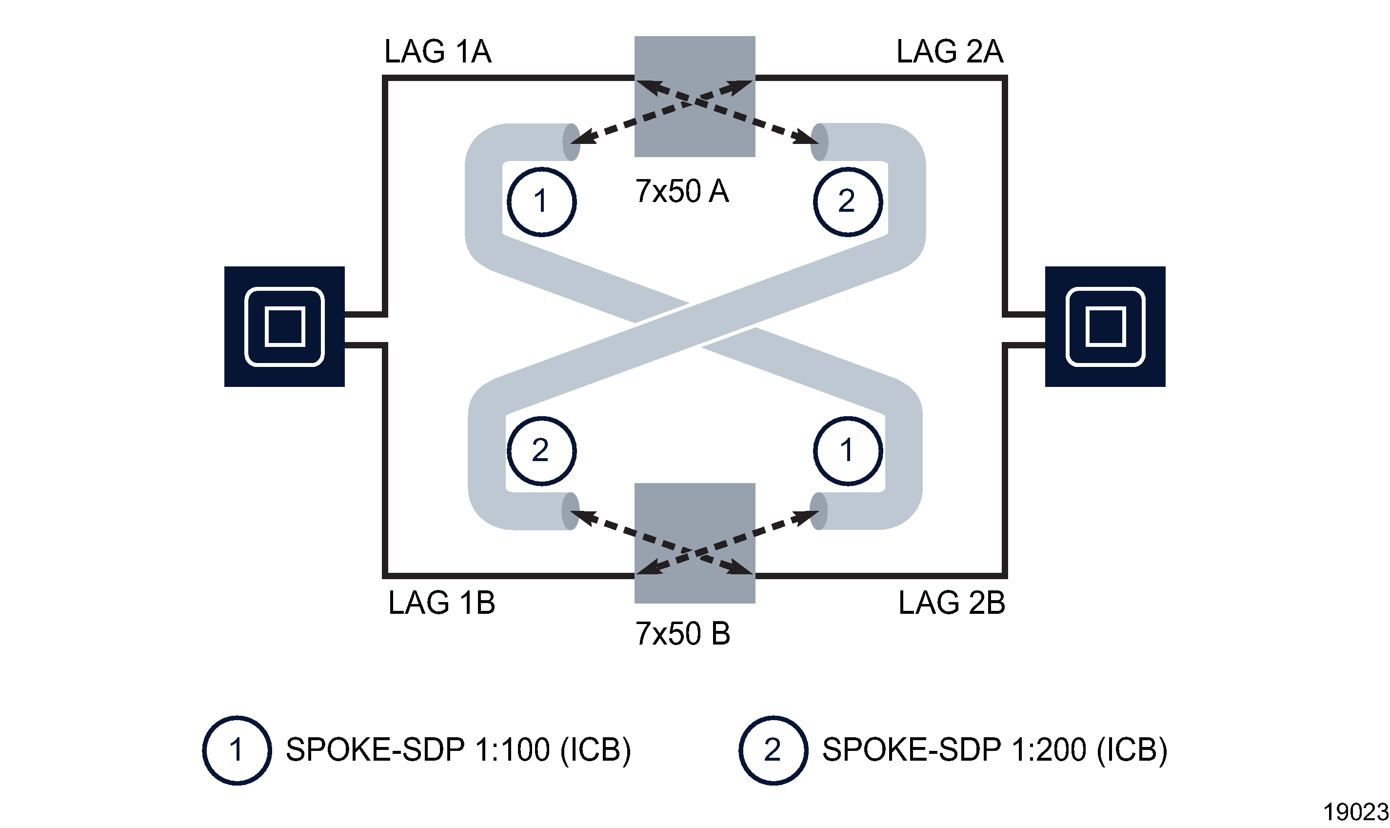
Figure 76-5: VLL redundancy configuration - option 7
Configuration requirements
You must consider the following configuration rules when provisioning VLL services with spoke switching and redundancy:
- Local endpoint rules:
-
A VLL instance has a maximum of two endpoints. A terminating VLL instance has at least one access endpoint and a switching VLL instance has two network endpoints.
-
A network endpoint has a maximum of four spoke-bindings, which can include any combination of the following: a single primary spoke, one or more secondary spokes with precedence, and one ICB spoke.
-
A SAP or a binding has a maximum of one endpoint association.
-
A SAP or a binding with association to an endpoint can be moved to another endpoint or removed from that endpoint.
-
- SAP rules:
- Spoke binding rules:
-
The SDP types (GRE, MPLS) used by the redundant spoke bindings do not have to be the same when you manually create the spoke bindings.
-
Redundant configurations are not supported for S-PE because there are a maximum of two spoke bindings for a switching VLL instance.
-
An ICB SDP binding should not be created on an endpoint without a MC-LAG SAP or MC-APS SAP.
-
ICB SDP binding can only have a precedence of 4, the lowest priority.
-
Spoke SDP binding cannot associate with an endpoint on a switching site.
-
- HSDPA offload fallback rules:
HSDPA Offload Resiliency
Mobile service providers deliver both voice and data services to their customers using mobile handsets. The data services provided require significantly more bandwidth than voice services. In order to minimize the operational costs (specifically, bandwidth), service providers typically separate the voice and data traffic at the mobile base station. The voice traffic may be backhauled over an ATM infrastructure, while a Metro Ethernet infrastructure (their own or third-party) is used to backhaul the data traffic. The separation of data traffic onto a separate network for backhaul is referred to as High Speed Data-Link Packet Access offload.
The HSDPA Apipe services traverse a path over the Metro Ethernet network which contains single potential points of failure that are unprotected. The ATM network can be used to provide a transient path for the data service in the event of a failure in the Metro Ethernet infrastructure, as long as the voice traffic is not impacted (data traffic is given lower QoS priority by the 7705 SAR and 7750 SR NEs). Clearly there is potential for the data service to suffer degradation (depending on the bandwidth required), until the fault in the Metro Ethernet network is resolved. However the SLA requirements for the data service are typically best effort.
The ability to switch to this alternate transient pathway for the data service is referred to as HSPDA resiliency.
HSPDA resiliency is implemented through the use of VLL Apipes on the 7705 SAR. The network architecture used in the ATM backhaul scenario is shown in Figure 76-6, ATM-based HSDPA offload architecture - nominal operation .
Note: For HSPDA offload resiliency, the primary and secondary services must be on the same NE.
Figure 76-6: ATM-based HSDPA offload architecture - nominal operation

The mobile base station node separates the voice and data traffic and delivers the two different traffic types to the 7705 SAR on different VCs. Both the voice and data services use Apipe pseudo-wires to carry the traffic over the backhaul network to the 7705 SAR. The HSDPA Apipe service is paired with an OAM service (not shown in Figure 76-6, ATM-based HSDPA offload architecture - nominal operation ) which is used by the wireless infrastructure to monitor the end-to-end path between the wireless endpoints.
For the ATM voice traffic, an internal Apipe is used on the 7705 SAR to switch ATM cells between the access VC/IMA group and the network side VC/IMA group. The service does not span the radio access network between the 7705 SAR and the 7750 SR located at the Mobile Telephone Switching Office (MTSO).
Data Apipe services (HSDPA/OAM) use service tunnels based on either MPLS or GRE. GRE is generally used in the context of a third-party Metro Ethernet network, since there is a Broadband Remote Access Server (BRAS) in the path between the DSLAM and the 7750 SR located at the MTSO (BRAS platforms do not support MPLS). MPLS is typically used when the mobile provider owns the Metro Ethernet network.
When the resiliency solution described below detects a failure in the Metro Ethernet network, its protection mechanism switches the traffic associated with the data service from the path over the Metro Ethernet network to a path which traverses the ATM (shown in the following figure). The detection, switchover, and switchback mechanisms are implemented by the NFM-P.
Figure 76-7: HSDPA Offload Protection - ATM data backhaul
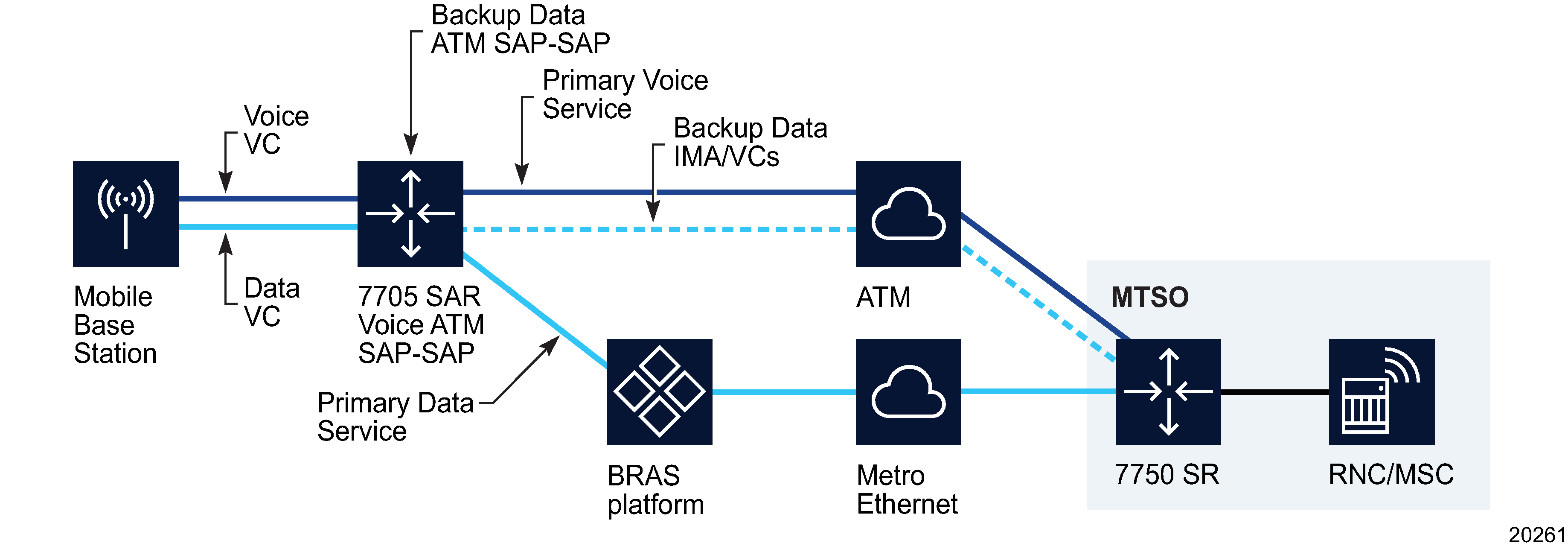
A backup (secondary) data service for an active (primary) data service is pre-configured on the 7705 SAR. For a typical 7705 SAR deployment at a cell site, two backup services are required, one for the HSDPA service and one for the OAM service. These backup services are created by the operator during the deployment of the 7705 SAR. A peer resiliency relationship between the active and backup services must also be configured.
The backup services used are internal Apipes. The switchover from primary to secondary is triggered by an event from the 7705 SAR sent to NFM-P, which indicates that the service tunnel (SDP) has failed. When the failure event is processed by NFM-P, the SAPs on the active data services are moved (along with the associated VCs) from the active service to its peer backup service and are enabled. After the re-configuration of the SAPs on the backup services completes, the traffic is moved to the backup services, which then carry the traffic over the ATM portion of the network. When the switchover is complete, an alarm is raised against the primary service indicating that it has been switched to the secondary service.
Other considerations include the following:
-
If a service configured as primary is deleted from NFM-P or the CLI, then the corresponding resiliency is also deleted.
-
If a service configured as secondary is deleted from NFM-P, this is blocked and a pop-up message indicates that the corresponding resiliency must first be deleted.
-
If a service configured as secondary is deleted from the CLI, an alarm is raised indicating that the resiliency is misconfigured. If a secondary service is then subsequently added to the resiliency, this alarm is cleared.
-
If the SAP initially configured on the primary service is deleted, the NFM-P raises an alarm. If the SAP is restored in the same service, the alarm clears.
-
When the NFM-P detects that a failed SDP is up, which indicates that the primary service has recovered, the resiliency is set to the Secondary (Debounced) state and a damping timer is started. If the SDP goes down while the resiliency is in the Secondary (Debounced) state, the resiliency changes to the Secondary state and the damping timer stops. If the SDP changes state during the damping time, the value of the damping timer doubles until it rises to the maximum damping time. This prevents the service from flapping between primary and secondary. If the SDP does not change operational state during the damping time, the resiliency is set to Primary, the SAP is moved from the secondary to the primary service, and the alarm related to the service switch clears.
-
After the primary service is restored, the damping timer value is set back to its initial value. The damping timer value is not displayed. The initial damping time is 30 000 ms; the time doubles, if required, to a maximum of 480 000 ms.
SDP bindings bandwidth allocation
You can administratively account for the bandwidth used by VLL services inside an RSVP SDP that consists of RSVP LSPs. The SR service manager keeps track of the available bandwidth for each SDP.
When you create a service tunnel, you configure an SDP Bandwidth Booking Factor percentage, which is applied to the SDP available bandwidth. You then assign an SDP Admin Bandwidth value (in kbps) to the spoke SDP. When you bind a VLL service to this SDP, this amount of bandwidth is subtracted from the adjusted available SDP bandwidth. If you subsequently delete the VLL service binding from this SDP, this bandwidth amount is added back into the adjusted SDP available bandwidth. If you overbook the total adjusted SDP available bandwidth when adding a VLL service, a warning is issued and the binding is rejected.
This feature does not guarantee bandwidth to a VLL service, as there is no change to the data path to enforce the bandwidth of an SDP by means such as shaping or policing of the constituent RSVP LSPs. Also, this feature does not provide a CAC capability for a local VLL service which consists of a cross-connect between two SAPs.
In addition, if multipoint services such as VPLS and VPRN are using the same SDP for forwarding packets, the amount of bandwidth consumed by these services is also not accounted for. Therefore, it is advisable to dedicate an SDP for VLL services for which bandwidth reservation is required. Furthermore, VPLS and VPRN services which use separate SDPs but which forward packets over the same network port as the VLL SDP also do not have their bandwidth accounted for. This may impact the bandwidth available to the VLL services.
Auto SDP binding (for all spoke bindings or just the return binding) cannot be used when there is a bandwidth request for the binding. The converse also applies. An error message appears when saving the configuration if this conflict occurs. NFM-P checking is done for the XML API.
Port redundancy
|
CAUTION Service Disruption |
Nokia recommends that you set the OLC state of a service to Maintenance before you switch to a redundant port or channel, and reset it to the previous state after the switch is complete. See the NSP System Administrator Guide for more information.
Cpipe and Epipe services on 7450 ESS, 7705 SAR, and 7750 SR devices support port redundancy, which allows you to define a backup port or channel for a VLL SAP. The backup port or channel can be on the local site, for what is called on-node switching, or on a remote site, for what is called off-node switching. In the event of a failure on the SAP, you can manually switch to the backup port or channel using a button on the VLL service, site, or SAP properties form, or from the port properties form.
When a SAP is switched to a backup port using off-node switching, the primary SAP on which the switching is performed is deleted along with the site and site child objects, including the associated SDP bindings. The site is subsequently created on the backup NE, as are the SAP and the other site child objects, using the same tunnel type and tunnel profile for SDP bindings as the primary site.
See To create a VLL L2 access interface on a terminating site for configuration information. See To switch to the redundant port for a VLL SAP from an L2 access interface properties form and To switch to the redundant port for one or more VLL SAPs for information about switching between the redundant ports of one or multiple VLL SAPs.
Note: Ethernet OAM objects, for example, MEPs, that are associated with the protected SAP are not copied to the new SAP.
When multiple SAPs are selected, switching is attempted only for the SAPs that support port redundancy and on which port redundancy is properly configured.
Port redundancy switching fails if the SAP or port is included in one of the following redundancy objects:
Copying and moving SAPs between ports
You can copy and move SAPs between ports. See Copying and moving SAPs in Chapter 16, Port and channel object configuration for more information.
DoS protection
To protect a VLL from a high incoming packet rate that characterizes a DoS attack, you can use the NFM-P to create DoS protection policies for VLL Epipe or Ipipe L2 access interfaces. A DoS protection policy limits the number of control-plane packets that an interface receives each second, and optionally logs a violation notification if a policy limit is exceeded. You can use the NE System Security form to view the violations for a specific NE.
You can configure a DoS protection policy to control the following on a VLL Epipe or Ipipe L2 access interface:
-
the control-plane packet arrival rate per subscriber host on the interface
-
the overall control-plane packet arrival rate for the interface
-
whether an NE sends a notification trap if a policy limit is exceeded
Each VPLS L2 access interface on an NE that supports DoS protection is automatically assigned a default DoS protection policy. The default policy limits only the overall packet arrival rate for the interface, and cannot be deleted or modified. See the NSP System Administrator Guide for information about creating a DoS protection policy.
DDoS protection
You can configure a DDoS protection policy on a VLL Epipe or Ipipe L2 access interface. See the NSP System Administrator Guide for information about configuring a DDoS protection policy.
BGP VPWS
You can use the NFM-P to create a BGP VPWS, which is an L2 VPN service that uses BGP pseudowire signaling. BGP VPWS is implemented in the NFM-P under an Epipe site, which is configured to use BGP to establish a pseudowire with a remote Epipe site. See To create a BGP VPWS for information about configuring a BGP VPWS.