vCPAA installation overview
General information
The vCPAA is supported on the following hypervisors:
The vCPAA supports two interface models: direct and bridge.
Direct interface model
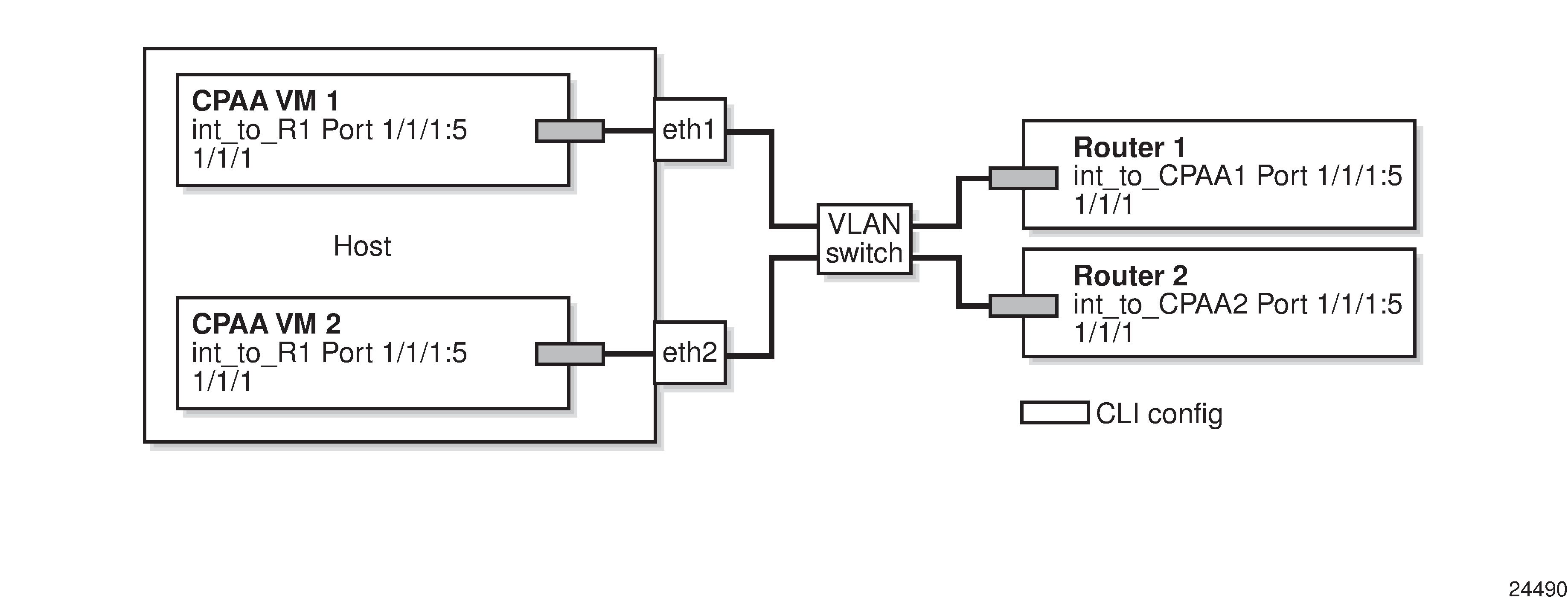
When the vCPAA is configured using the direct interface model, the hypervisor creates a one-to-one binding between the VM network interface and a physical network interface on the host. As such, the number of vCPAAs is limited to the number of physical network interfaces assigned on the host. Multiple interfaces may be specified per vCPAA using qtags (dot1.q). See the direct interface model deployment example in the following figure:
Figure 4-1: vCPAA direct interface model deployment

where
int_to_port is a sample interface configured inside the VM
Note: IP management port diagrams are not shown.
VLAN switch programming is operator-dependent.
The direct interface model can also be deployed using sub-interfaces on the host rather than physical network interfaces. This allows the number of vCPAAs to exceed the number of physical network interfaces assigned on the host, however, each vCPAA has only four logical ports and therefore, only four interface adjacencies. See the direct interface model using sub-interfaces deployment example in the following figure:
Figure 4-2: vCPAA direct interface model using sub-interfaces deployment

where
int_to_port is a sample interface configured inside the VM
Note: IP management port diagrams are not shown.
VLAN switch programming is operator dependent.
Bridge interface model
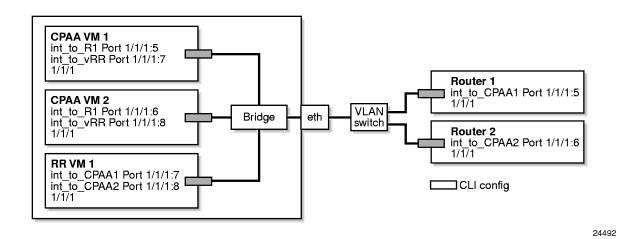
When the vCPAA is configured using the bridge interface model, the hypervisor connects the VM network interface to a host bridge. Physical network interfaces are also connected to the host bridge, allowing vCPAAs to share physical network interfaces and communicate internally. Logical ports configured on these vCPAAs must have different tag values. The bridge interface model is required for host programming, and is recommended for eth0 VM network interfaces (associated with the A/1 management port). See the bridge interface model deployment example in the following figure:
Figure 4-3: vCPAA bridge interface model deployment

where
int_to_port is a sample interface configured inside the VM
Note: IP management port diagrams are not shown.
VLAN switch programming is operator dependent.
vCPAA installation
You can install the vCPAA using either a KVM or a VMware hypervisor.
If you are using VMware, see To deploy a vCPAA on VMware using the vSphere Client.
Note: The process for installing a vCPAA on VMware is user-specific, and may vary depending on your system configuration. For issues that are not resolved by existing resources, contact your Nokia representative for assistance.
If you are using KVM, see vCPAA installation workflow for KVM.
© 2022 Nokia. Nokia Confidential Information
Use subject to agreed restrictions on disclosure and use.