Internal NSP communication
Introduction
Communication among NSP cluster members and other components in na NSP deployment is performed over the internal network. Each internal interface is secured using TLS. TLS is also applied to the communication among internal NSP system services and processes.
Each NSP cluster member has a unique IP address; however, the cluster members share one virtual IP address for access by other components.
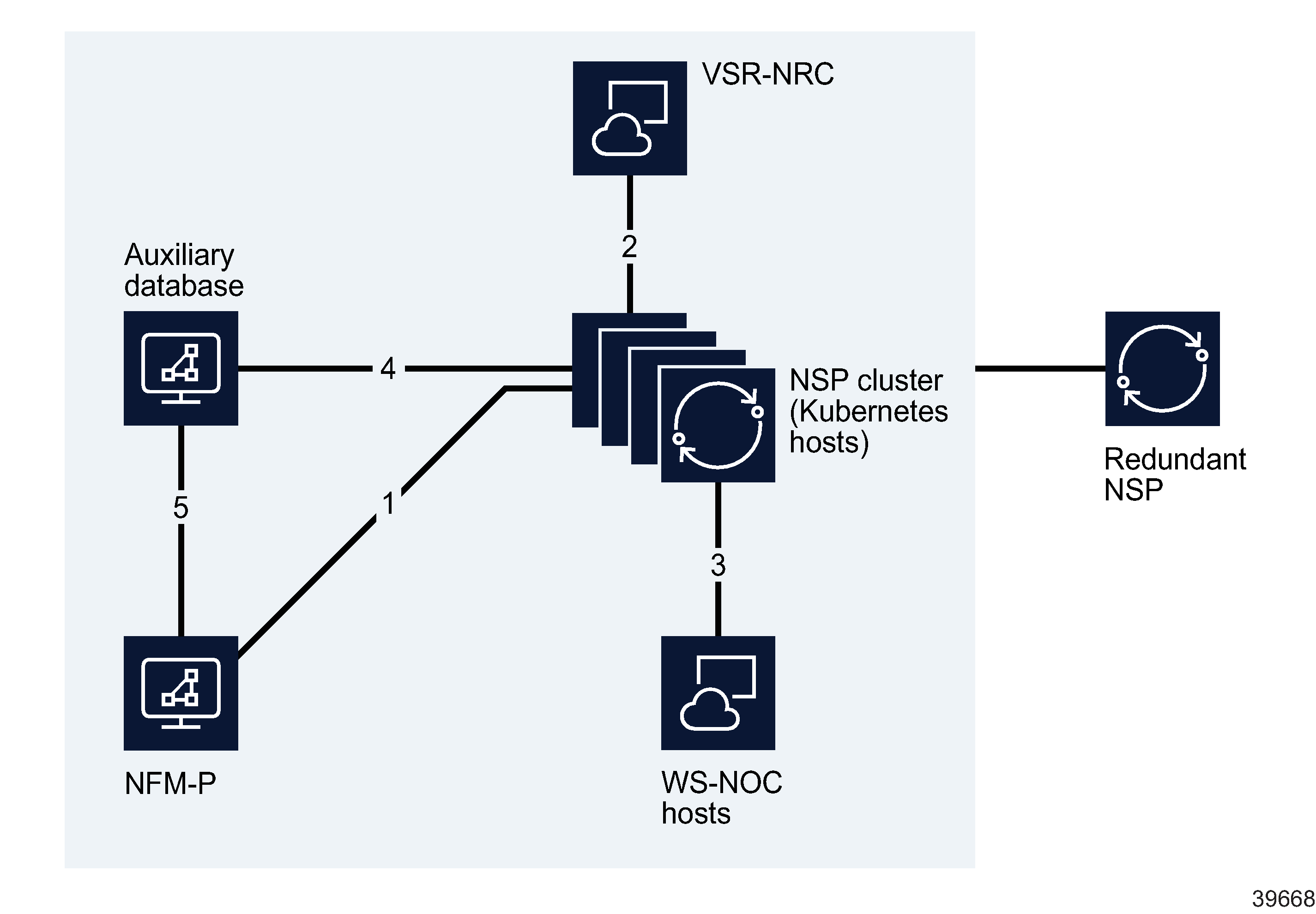
Figure 7-3: Internal NSP interfaces
The following table describes each interface shown in Figure 7-3, Internal NSP interfaces.
Table 7-3: Internal NSP connections
|
Interface |
Endpoints |
Traffic type |
|---|---|---|
|
1 |
NFM-P NSP cluster |
SSO authentication. Zookeeper registration, Kafka messaging, NFM-P API |
|
2 |
NSP cluster VSR-NRC (BOF interface) |
Data connection – CPROTO (non-secure) |
|
3 |
WS-NOC NSP cluster |
SSO authentication, Zookeeper registration (non-secure), REST over HTTPS, proprietary WS-NOC HTTP communication |
|
4 |
NSP cluster NSP auxiliary database |
Database transactions, RESTCONF API calls |
|
5 |
NFM-P NSP auxiliary database |
Database transactions |
Communication between redundant data centers
NSP geographic redundancy, sometimes called geo-redundancy, uses a disaster-recovery (DR) mechanism to engage an identical NSP cluster at a standby site to support service continuity in the event that the primary site suffers an unrecoverable failure. To effectively support a DR NSP deployment, the NSP clusters at the geo-redundant sites require robust, secure communication.
The following NSP components perform DR communication over the internal NSP network:
For more information about DR deployments, see Chapter 8, System redundancy and fault tolerance.
