RSVP Point-to-Point LSPs
This chapter provides information about point-to-point label switched paths (LSPs) established using resource reservation protocol (RSVP) with or without traffic engineering (TE).
Topics in this chapter include:
Applicability
This chapter was initially written for SR OS Release 7.0.R5, but the MD-CLI in the current edition is based on SR OS Release 21.2.R1. There are no prerequisites or conditions on the hardware for this configuration.
Overview
Due to the connectionless nature of the network layer protocol IP, packets travel through the network on a hop-by-hop basis with routing decisions made at each node. As a result, hyperaggregation of data on certain links may occur and it may impact the provider's ability to provide guaranteed service levels across the network end-to-end. To address these shortcomings, Multi-Protocol Label Switching (MPLS) was developed. MPLS provides the capability to establish connection-oriented paths, called Label Switched Paths (LSPs), over a connectionless (IP) network.
The LSP offers a mechanism to engineer network traffic independently from the underlying network routing protocol (mostly IP) to improve the network resiliency and recovery options and to permit delivery of new services that are not readily supported by conventional IP routing techniques, such as Layer 2 IP Virtual Private Networks (VPNs). These benefits are essential for today's communication network explaining the wide deployment base of the MPLS technology.
RFC 3031, Multiprotocol Label Switching Architecture, specifies the MPLS architecture whereas this document describes the configuration and troubleshooting of RSVP point-to-point LSPs on SR OS. Besides RSVP P2P LSPs, there are also Static Point-to-Point LSPs, LDP Point-to-Point LSPs, and Segment Routing (SR) LSPs (SR-ISIS, SR-OSPF, and SR-TE). For SR-ISIS, see chapter Segment Routing with IS-IS Control Plane.
Packet forwarding
As a packet of a connectionless network layer protocol travels from one router to the next, each router in the network makes an independent forwarding decision by performing the following basic tasks: first analyzing the packet header, then referencing the local routing table to find the longest match based on the destination address in the IP header, and finally sending out the packet on the selected interface. In other words, the first function partitions the entire set of possible packets into a set of Forwarding Equivalence Classes (FECs). All packets associated to a particular FEC will be forwarded along the same logical path to the same destination. The second function maps each FEC to a next hop destination router. Each router along the data path performs these actions.
In MPLS, the assignment of a packet to a particular FEC is done just once, as the packet enters the network. In turn, the FEC is mapped to an LSP, which is pre-signaled prior to any data flowing. An MPLS label, representing the FEC to which the packet is assigned, is attached to the packet (push operation) and once labeled, the packet is forwarded to the next hop router along that LSP path.
At subsequent hops, there is no further analysis of the packet network layer header. Instead, the label is used as an index into a table which specifies the next hop and a new label. The old label is replaced with the new label (swap operation), and the packet is forwarded to its next hop.
At the MPLS network egress, the label is removed from the packet (pop operation). If this router is the destination (based on the remaining packet), the packet is handed to the receiving application, such as a Virtual Private LAN Service (VPLS). If this router is not the final destination of the packet, the packet will be sent into a new MPLS tunnel or forwarded by conventional IP forwarding toward the Layer 3 destination.
Terminology
Generic MPLS network, MPLS label operations shows a general network topology clarifying the MPLS-related terms.
A Label Edge Router (LER) is a device at the edge of an MPLS network, with at least one interface outside the MPLS domain. A router is usually defined as an LER based on its position relative to a particular LSP. The MPLS router at the head-end of an LSP is called the ingress Label Edge Router (iLER). The MPLS router at the tail-end of an LSP is called the egress Label Edge Router (eLER).
The iLER receives unlabeled packets from outside the MPLS domain, then applies MPLS labels to the packets, and forwards the labeled packets into the MPLS domain. The eLER receives labeled packets from the MPLS domain, then removes the labels, and forwards unlabeled packets outside the MPLS domain. The eLER can signal an implicit-null label (numeric value 3). This informs the previous hop to send MPLS packets without an outer label and is known as Penultimate Hop Popping (PHP).
A Label Switching Router (LSR) is a device internal to an MPLS network, with all interfaces inside the MPLS domain. These devices switch labeled packets inside the MPLS domain. In the core of the network, LSRs ignore the packet network layer (IP) header and simply forward the packet using the MPLS label swapping mechanism.
A single LSP is unidirectional. In common practice, because the bidirectional nature of most traffic flows is implied, the term LSP often is used to define the pair of LSPs that enable the bidirectional flow. For ease of terminology and discussion however, the LSP in this chapter is referred to as a single entity.
LSP establishment
Prior to packet forwarding, the LSP must be established. In order to do so, labels need to be distributed for the path. Labels are usually distributed by a downstream router in the upstream direction (relative to the data flow). There are a number of ways used for label distribution: static, LDP, and RSVP. For static P2P LSPs, see chapter Static Point-to-Point LSPs; for LDP P2P LSPs, see chapter LDP Point-to-Point LSPs.
RSVP-TE (RFC 3209, RSVP-TE: Extensions to RSVP for LSP Tunnels) can be used to signal LSPs across the network. RSVP-TE is used for traffic engineering when the ingress router creates an LSP with specific constraints beyond the best route chosen by the IGP. RSVP-TE identifies the specific path desired for the LSP and may include resource requirements for the path.
The most important benefit of the label swapping mechanism RSVP-TE is its ability to map any type of user traffic to an LSP that has been specifically engineered to satisfy user traffic requirements. Customized LSPs may be created based on hop count, bandwidth requirements, administrative groups, or Shared Risk Link Groups (SRLGs). They can even be routed through a strict path with specific network links or nodes, as specified by the ingress node. This offers service providers precise control over the flow of traffic in their networks and results in a network that operates more efficiently and provides more predictable and scalable services. For information about SRLG, see chapter Shared Risk Link Groups for RSVP-Based LSPs.
Fast reroute (FRR) allows to signal backup paths before a failure takes place. This allows traffic to flow almost continuously, without waiting for routing protocol convergence. Two different FRR methods exist for RSVP-TE LSPs: one-to-one and facility.
-
FRR one-to-one defines detour tunnels toward the eLER for a particular LSP only. The advantage is that the detour tunnel is the best path to the eLER that avoids the node or link at the point of failure. The drawback is that when different LSPs would need the same detour, a dedicated RSVP-TE detour LSP needs to be signaled for each LSP.
-
FRR facility defines local repair tunnels avoiding one particular node (the next hop in the data path) or one particular link (the next link in the data path), ignoring the eLER. These bypass tunnels originate in a point of local repair (PLR) and terminate in a merge point (MP) on the LSP. Bypass tunnels are shared between LSPs.
Example topology
MPLS example topology shows the example topology consisting of six SR OS nodes located in a single autonomous system.
Configuration
In this chapter, RSVP LSPs are configured manually, but they can also be configured automatically using LSP templates; see chapter Automatic Creation of RSVP-TE LSPs.
As a general prerequisite for the configuration of MPLS LSPs, a correctly working Interior Gateway Protocol (IGP) is required. Open Shortest Path First (OSPF) or Intermediate System to Intermediate System (IS-IS) can be used as IGP.
RSVP-TE, an extension of the original RSVP protocol, has two major benefits adding to the basic MPLS functionality. The first benefit is traffic engineering, which allows the ingress router to create an LSP with specific constraints beyond the best route chosen by the IGP. The second benefit is improved network resiliency when a link or node fails in the network, using FRR and secondary paths. FRR is also supported for LDP, see chapter MPLS LDP FRR using ISIS as IGP.
In this chapter, several RSVP-TE LSPs are configured:
-
A simple LSP with a primary path that has strict hops and no specific TE constraints
-
A simple LSP with a dynamic path without any configured hops is created. Initially, there are no constraints and the actual path is calculated based on the IGP best route.
-
An LSP configured with constrained shortest path first (CSPF) that will use the TE metric, even though the IGP metric can also be used
-
An LSP with fast reroute (FRR) one-to-one enabled
-
An LSP with FRR facility enabled
-
An LSP including an admin group "blue" and an LSP excluding admin group "red"
-
An LSP with a hop limit configured
There is no configuration example with bandwidth constraints configured in this chapter. See chapter "Automatic Bandwidth Adjustment" in P2P LSPs in the MPLS volume of 7450 ESS, 7750 SR, and 7950 XRS Advanced Configuration Guide — Part I for a configuration with bandwidth constraint with or without automatic adjustment.
Initially, no traffic engineering is enabled in the ISIS context, but it will be enabled when required. For RSVP LSPs, MPLS and RSVP need to be enabled on each router and all network interfaces facing the MPLS domain. For PE-1, the following configuration is required:
# on PE-1:
configure {
    router "Base" {
        mpls {
            admin-state enable
            interface "int-PE-1-PE-2" {
            }
            interface "int-PE-1-PE-4" {
            }
        }
        rsvp {
            admin-state enable
            interface "int-PE-1-PE-2" {
            }
            interface "int-PE-1-PE-4" {
            }
        }
Strict or loose path
On the iLER, first the definition of a path is required. A path is a sequence of MPLS routers (hops) through which the LSP using that path has to pass. It is not uniquely bound to a particular LSP; it can be used by any LSP originating in that node. A hop in a path can be strict or loose: strict or loose meaning that the LSP must take either a direct path from the previous hop router to this router (strict) or can traverse through other routers (loose). The hops not explicitly defined in the loose path definition are created by calculating the IGP shortest path. A third possibility is an empty path implying not a single node is required to be present in the LSP path and the shortest path from the IGP is used to define the LSP path. Other techniques, such as the use of admin groups or shared risk link groups, can also be used to influence the decision which hops to include in the path. Three paths will be configured, respectively:
-
Only strict hops
-
Mixed strict and loose hops
-
Empty path
To find a valid path, the last hop in the path sequence needs to be the system IP or an interface address of the terminating router (eLER). The IP addresses in the hop command can be the system IP addresses or the interface addresses of the node. However, it is recommended to use the system IP addresses with keyword loose because this allows more flexibility when finding new paths in failover scenarios (because the upstream node could use any of multiple paths to the system address, whereas specifying the interface address would restrict the upstream node to a single entry-point). The recommendation when using the keyword strict in the hop command context, is to use the physical link addresses.
The last hop in the path should be a system address to make it appear in the list on the 5620 SAM (service-aware manager).
# on PE-1:
configure {
    router "Base" {
        mpls {
            path "dyn" {
                admin-state enable
            }
            path "path-PE-1-PE-6-semiLoose" {
                admin-state enable
                hop 10 {
                    ip-address 192.0.2.5
                    type loose
                }
                hop 20 {
                    ip-address 192.168.56.2
                    type strict
                }
            }
            path "path-PE-1-PE-6-strict" {
                admin-state enable
                hop 10 {
                    ip-address 192.168.12.2
                    type strict
                }
                hop 20 {
                    ip-address 192.168.25.2
                    type strict
                }
                hop 30 {
                    ip-address 192.168.56.2
                    type strict
                }
            }
The paths can be checked with the show router mpls path command.
[/]
A:admin@PE-1# show router mpls path

===============================================================================
MPLS Path:
===============================================================================
Path Name                                                        Admin  PathIdx
Hop Index  IP Address/SID-Label                                  Strict/Loose
-------------------------------------------------------------------------------
dyn                                                              Up     1
no hops    n/a                                                   n/a

path-PE-1-PE-6-semiLoose                                         Up     2
10         192.0.2.5                                             Loose
20         192.168.56.2                                          Strict

path-PE-1-PE-6-strict                                            Up     3
10         192.168.12.2                                          Strict
20         192.168.25.2                                          Strict
30         192.168.56.2                                          Strict

-------------------------------------------------------------------------------
Total Paths : 3
===============================================================================
Simple RSVP LSP with strict primary path
The configuration of a simple LSP using RSVP signaling contains at least on the iLER:
-
System IP address of the terminating node (to)
-
Path to the eLER (primary)
-
Administratively enabled
# on PE-1:
configure {
    router "Base" {
        mpls {
            lsp "LSP-PE-1-PE-6" {
                admin-state enable
                type p2p-rsvp
                to 192.0.2.6
                primary "path-PE-1-PE-6-strict" {
                }
                secondary "dyn" {
                }
            }
All the hops in the strict path are already defined and there is no need to look up the IGP best route. The configuration of secondary paths is optional. In case the primary path fails, the secondary path can be signaled to take over the traffic. It can even be signaled as standby while the primary path is operational for a faster switchover when the keyword standby is added, which is not the case here. The secondary path has no hops defined. The hops will be calculated based on the IGP best route. The nodes through which the LSP will pass (LSRs and eLER) require no additional configuration: enabling MPLS and RSVP on their interfaces suffices.
An overview of all LSPs configured on a particular node is given by the show router mpls lsp command. More details about a particular LSP can be retrieved by adding the keyword detail to the previous command.
[/]
A:admin@PE-1# show router mpls lsp

===============================================================================
MPLS LSPs (Originating)
===============================================================================
LSP Name                                            Tun     Fastfail  Adm  Opr
  To                                                Id      Config
-------------------------------------------------------------------------------
LSP-PE-1-PE-6                                       1       No        Up   Up
  192.0.2.6
-------------------------------------------------------------------------------
LSPs : 1
===============================================================================
[/]
A:admin@PE-1# show router mpls lsp "LSP-PE-1-PE-6" detail

===============================================================================
MPLS LSPs (Originating) (Detail)
===============================================================================
Legend :
    + - Inherited
===============================================================================
-------------------------------------------------------------------------------
Type : Originating
-------------------------------------------------------------------------------
LSP Name   : LSP-PE-1-PE-6
LSP Type        : RegularLsp                LSP Tunnel ID        : 1
LSP Index       : 1                         TTM Tunnel Id        : 1
From            : 192.0.2.1
To              : 192.0.2.6
Adm State       : Up                        Oper State           : Up
LSP Up Time     : 0d 00:00:37               LSP Down Time        : 0d 00:00:00
Transitions     : 1                         Path Changes         : 1
Retry Limit     : 0                         Retry Timer          : 30 sec
Signaling       : RSVP                      Resv. Style          : SE
Hop Limit       : 255                       Negotiated MTU       : 1564
Adaptive        : Enabled                   ClassType            : 0
FastReroute     : Disabled                  Oper FR              : Disabled
PathCompMethod  : none                      ADSPEC               : Disabled
FallbkPathComp  : not-applicable
Metric          : N/A
Load Bal Wt     : N/A                       ClassForwarding      : Disabled
Include Grps    :                           Exclude Grps         :
None                                           None
Least Fill      : Disabled
BFD Template    : None                      BFD Ping Intvl       : 60
BFD Enable      : False                     BFD Failure-action   : None
WaitForUpTimer  : 4

Revert Timer    : Disabled                  Next Revert In       : N/A
Entropy Label   : Enabled+                  Oper Entropy Label   : Enabled
Negotiated EL   : Disabled
Auto BW         : Disabled
LdpOverRsvp     : Enabled
VprnAutoBind    : Enabled
IGP Shortcut    : Enabled                   BGP Shortcut         : Enabled
IGP LFA         : Disabled                  IGP Rel Metric       : Disabled
BGPTransTun     : Enabled
Oper Metric     : 16777215
Prop Adm Grp    : Disabled
PCE Report      : Disabled+
PCE Control     : Disabled
Path Profile    : None
Admin Tags      : None
Lsp Self Ping   : Disabled+                 Self Ping Timeouts   : 0
SelfPingOAMFail*: 0

Secondary       : dyn
                                            Down Time            : 0d 00:00:37
Bandwidth       : 0 Mbps
Primary(a)      : path-PE-1-PE-6-strict
                                            Up Time              : 0d 00:00:37
Bandwidth       : 0 Mbps
===============================================================================
* indicates that the corresponding row element may have been truncated.
In each hop (originating, transit and terminate), the RSVP sessions can be verified as follows:
[/]
A:admin@PE-1# show router rsvp session

===============================================================================
RSVP Sessions
===============================================================================
RSVP Session Name
    From                To              Tunnel ID   LSP ID       State
-------------------------------------------------------------------------------
LSP-PE-1-PE-6::path-PE-1-PE-6-strict
192.0.2.1           192.0.2.6           1           13824        Up

-------------------------------------------------------------------------------
Sessions : 1
===============================================================================
The detailed output of this command includes among others the session type (here: originate), the incoming and outgoing labels, the previous and next hop, and - for originating LSPs - also the list of hops):
[/]
A:admin@PE-1# show router rsvp session detail

===============================================================================
RSVP Sessions (Detailed)
===============================================================================
-------------------------------------------------------------------------------
LSP : LSP-PE-1-PE-6::path-PE-1-PE-6-strict
-------------------------------------------------------------------------------
From            : 192.0.2.1             To             : 192.0.2.6
Tunnel ID       : 1                     LSP ID         : 13824
Style           : SE                    State          : Up
Session Type    : Originate
In Interface    : n/a                   Out Interface  : 1/1/1
In IF Name      : n/a
Out IF Name     : int-PE-1-PE-2
In Label        : n/a                   Out Label      : 524287
Previous Hop    : n/a                   Next Hop       : 192.168.12.2
Hops            :
                  192.168.12.2(S)
               -> 192.168.25.2(S)
               -> 192.168.56.2(S)
SetupPriority   : 7                     Hold Priority  : 0
Class Type      : 0
SubGrpOrig ID   : 0                     SubGrpOrig Addr:
P2MP ID         : 0
FrrAvailType    : N/A
FrrSrlgStrict   : N/A                   SrlgDisjoint   : N/A

Path Recd       : 0                     Path Sent      : 4
Resv Recd       : 3                     Resv Sent      : 0
Summary msgs    :
SPath Recd      : 0                     SPath Sent     : 0
SResv Recd      : 0                     SResv Sent     : 0
LSP Attr Flags  : N/A
===============================================================================
The following RSVP LSP is in the tunnel table on PE-1:
[/]
A:admin@PE-1# show router tunnel-table

===============================================================================
IPv4 Tunnel Table (Router: Base)
===============================================================================
Destination           Owner     Encap TunnelId  Pref   Nexthop        Metric
   Color
-------------------------------------------------------------------------------
192.0.2.6/32          rsvp      MPLS  1         7      192.168.12.2   16777215
-------------------------------------------------------------------------------
Flags: B = BGP or MPLS backup hop available
       L = Loop-Free Alternate (LFA) hop available
       E = Inactive best-external BGP route
       k = RIB-API or Forwarding Policy backup hop
===============================================================================
In order to signal PHP with RSVP, implicit-null must be configured on the eLER.
# on PE-6:
configure {
    router "Base" {
        rsvp {
            implicit-null-label true
The implicit-null is signaled and is shown on PE-5 as an egress label of 3. This label is not actually sent toward PE-6.
[/]
A:admin@PE-5# show router rsvp session detail

===============================================================================
RSVP Sessions (Detailed)
===============================================================================
-------------------------------------------------------------------------------
LSP : LSP-PE-1-PE-6::path-PE-1-PE-6-strict
-------------------------------------------------------------------------------
From            : 192.0.2.1             To             : 192.0.2.6
Tunnel ID       : 1                     LSP ID         : 13828
Style           : SE                    State          : Up
Session Type    : Transit
In Interface    : 1/1/3                 Out Interface  : 1/1/2
In IF Name      : int-PE-5-PE-2
Out IF Name     : int-PE-5-PE-6
In Label        : 524287                Out Label      : 3
Previous Hop    : 192.168.25.1          Next Hop       : 192.168.56.2
---snip---
The use of implicit-null can also be enabled/disabled on a per interface basis:
# on PE-6:
configure {
    router "Base" {
        rsvp {
            interface "int-PE-6-PE-5"
                implicit-null-label true
In the remainder of the chapter, LSPs with empty paths will be used. LSP "LSP-PE-1-PE-6" is administratively disabled.
Simple RSVP LSP with dynamic path
In this section, an LSP is configured from PE-1 to PE-3 with a dynamic path that is empty. There is no secondary path. LSP "LSP-PE-1-PE-3" is configured as follows:
# on PE-1:
configure {
    router "Base" {
        mpls {
            lsp "LSP-PE-1-PE-3" {
                admin-state enable
                type p2p-rsvp
                to 192.0.2.3
                primary "dyn" {
                }
Interfaces with a lower metric will be preferred over links with a high metric. The default IGP metric in this example is 10. The metric is lower for higher speed links, but can be configured manually; as follows:
# on PE-1:
configure {
    router "Base" {
        isis 0 {
            interface "int-PE-1-PE-2" {
                level 1 {
                    metric 1000
                }
The link between PE-1 and PE-2 has a higher metric and will not be selected for forwarding traffic because the route via PE-4 has a lower metric. The routing table shows that the route to prefix 192.0.2.3 has PE-4 as next hop instead of PE-2 and that the metric is 40:
[/]
A:admin@PE-1# show router route-table 192.0.2.3

===============================================================================
Route Table (Router: Base)
===============================================================================
Dest Prefix[Flags]                            Type    Proto     Age        Pref
      Next Hop[Interface Name]                                    Metric
-------------------------------------------------------------------------------
192.0.2.3/32                                  Remote  ISIS      00h02m45s  15
       192.168.14.2                                                 40
-------------------------------------------------------------------------------
No. of Routes: 1
Flags: n = Number of times nexthop is repeated
       B = BGP backup route available
       L = LFA nexthop available
       S = Sticky ECMP requested
===============================================================================
LSP with dynamic path takes IGP best route shows the path used by the LSP:
The actual hops can be verified in the following output. The path is dynamic, therefore, no explicit hops are configured.
[/]
A:admin@PE-1# show router mpls lsp "LSP-PE-1-PE-3" path detail

===============================================================================
MPLS LSP LSP-PE-1-PE-3 Path  (Detail)
===============================================================================
Legend :
    @ - Detour Available              # - Detour In Use
    b - Bandwidth Protected           n - Node Protected
    s - Soft Preemption
    S - Strict                        L - Loose
    A - ABR                           + - Inherited
===============================================================================
-------------------------------------------------------------------------------
LSP LSP-PE-1-PE-3
Path dyn
-------------------------------------------------------------------------------
LSP Name    : LSP-PE-1-PE-3
From             : 192.0.2.1
To               : 192.0.2.3
Admin State      : Up                      Oper State        : Up
Path Name   : dyn
Path LSP ID      : 45056                   Path Type         : Primary
Path Admin       : Up                      Path Oper         : Up
Out Interface    : 1/1/2                   Out Label         : 524287
---snip---

Explicit Hops    :
    No Hops Specified
Actual Hops      :
    192.168.14.1(192.0.2.1)                      Record Label        : N/A
 -> 192.168.14.2(192.0.2.4)                      Record Label        : 524287
 -> 192.168.45.2(192.0.2.5)                      Record Label        : 524287
 -> 192.168.25.1(192.0.2.2)                      Record Label        : 524287
 -> 192.168.23.2(192.0.2.3)                      Record Label        : 524287
Resignal Eligible: False
Last Resignal    : n/a                     CSPF Metric       : 0
===============================================================================
The tunnel table shows the RSVP LSP with PE-4 as the next hop and a metric of 40:
[/]
A:admin@PE-1# show router tunnel-table

===============================================================================
IPv4 Tunnel Table (Router: Base)
===============================================================================
Destination           Owner     Encap TunnelId  Pref   Nexthop        Metric
   Color
-------------------------------------------------------------------------------
192.0.2.3/32          rsvp      MPLS  2         7      192.168.14.2   40
-------------------------------------------------------------------------------
Flags: B = BGP or MPLS backup hop available
       L = Loop-Free Alternate (LFA) hop available
       E = Inactive best-external BGP route
       k = RIB-API or Forwarding Policy backup hop
===============================================================================
RSVP-TE LSP with dynamic path
Traffic engineering is enabled in the ISIS context on all nodes; as follows:
# on all PEs:
configure {
    router "Base" {
        isis 0 {
            traffic-engineering
The LSP can be configured with constrained shortest path first (CSPF); as follows:
# on PE-1:
configure {
    router "Base" {
        mpls {
            lsp "LSP-PE-1-PE-3" {
                path-computation-method local-cspf
For this LSP, it will not make any difference. By default, the IGP metrics are used and the LSP path takes the IGP shortest path.
Besides IGP metrics, also TE metrics can be configured; as follows:
# on PE-2:
configure {
    router "Base" {
        mpls {
            interface "int-PE-2-PE-1" {
                te-metric 10
            }
            interface "int-PE-2-PE-3" {
                te-metric 500
            }
            interface "int-PE-2-PE-5" {
                te-metric 10
            }
In this example, all interfaces on all PEs get a TE metric of 10, except for the interfaces between PE-1 and PE-4, which get a TE metric of 100 and the interfaces between PE-2 and PE-3, which get a TE metric of 500. Even with these TE metrics configured, the LSP path will not change, because the IGP metric is used by default, as can be verified as follows:
[/]
A:admin@PE-1# show router mpls lsp "LSP-PE-1-PE-3" path detail

===============================================================================
MPLS LSP LSP-PE-1-PE-3 Path  (Detail)
===============================================================================
Legend :
    @ - Detour Available              # - Detour In Use
    b - Bandwidth Protected           n - Node Protected
    s - Soft Preemption
    S - Strict                        L - Loose
    A - ABR                           + - Inherited
===============================================================================
-------------------------------------------------------------------------------
LSP LSP-PE-1-PE-3
Path dyn
-------------------------------------------------------------------------------
LSP Name    : LSP-PE-1-PE-3
From             : 192.0.2.1
To               : 192.0.2.3
Admin State      : Up                      Oper State        : Up
Path Name   : dyn
Path LSP ID      : 45058                   Path Type         : Primary
Path Admin       : Up                      Path Oper         : Up
Out Interface    : 1/1/2                   Out Label         : 524286
---snip---

Adaptive         : Enabled                 Oper Metric       : 40
Preference       : n/a
Path Trans       : 2                       CSPF Queries      : 1
Failure Code     : noError
Failure Node : n/a
Explicit Hops    :
    No Hops Specified
Actual Hops      :
    192.168.14.1(192.0.2.1)                      Record Label        : N/A
 -> 192.168.14.2(192.0.2.4)                      Record Label        : 524286
 -> 192.168.45.2(192.0.2.5)                      Record Label        : 524286
 -> 192.168.25.1(192.0.2.2)                      Record Label        : 524286
 -> 192.168.23.2(192.0.2.3)                      Record Label        : 524286
Computed Hops    :
    192.168.14.1(S)
 -> 192.168.14.2(S)
 -> 192.168.45.2(S)
 -> 192.168.25.1(S)
 -> 192.168.23.2(S)
Resignal Eligible: False
Last Resignal    : n/a                     CSPF Metric       : 40
---snip---
The RSVP LSP in the tunnel table has next hop PE-4 and a metric of 40:
[/]
A:admin@PE-1# show router tunnel-table

===============================================================================
IPv4 Tunnel Table (Router: Base)
===============================================================================
Destination           Owner     Encap TunnelId  Pref   Nexthop        Metric
   Color
-------------------------------------------------------------------------------
192.0.2.3/32          rsvp      MPLS  2         7      192.168.14.2   40
-------------------------------------------------------------------------------
Flags: B = BGP or MPLS backup hop available
       L = Loop-Free Alternate (LFA) hop available
       E = Inactive best-external BGP route
       k = RIB-API or Forwarding Policy backup hop
===============================================================================
To force the LSP to use the TE metric, the LSP is reconfigured as follows:
# on PE-1:
configure {
    router "Base" {
        mpls {
            lsp "LSP-PE-1-PE-3" {
                path-computation-method local-cspf
                metric-type te
The LSP path is shown in RSVP-TE LSP with dynamic path using TE metric:
The LSP path goes from PE-1 to PE-2 and via PE-5 and PE-6 to PE-3, as can be seen in the following output. The CSPF metric is 40, which corresponds to the TE metric in this case:
[/]
A:admin@PE-1# show router mpls lsp "LSP-PE-1-PE-3" path detail

===============================================================================
MPLS LSP LSP-PE-1-PE-3 Path  (Detail)
===============================================================================
Legend :
    @ - Detour Available              # - Detour In Use
    b - Bandwidth Protected           n - Node Protected
    s - Soft Preemption
    S - Strict                        L - Loose
    A - ABR                           + - Inherited
===============================================================================
-------------------------------------------------------------------------------
LSP LSP-PE-1-PE-3
Path dyn
-------------------------------------------------------------------------------
LSP Name    : LSP-PE-1-PE-3
From             : 192.0.2.1
To               : 192.0.2.3
Admin State      : Up                      Oper State        : Up
Path Name   : dyn
Path LSP ID      : 45060                   Path Type         : Primary
Path Admin       : Up                      Path Oper         : Up
Out Interface    : 1/1/1                   Out Label         : 524287
---snip---

Adaptive         : Enabled                 Oper Metric       : 16777215
Preference       : n/a
Path Trans       : 4                       CSPF Queries      : 2
Failure Code     : noError
Failure Node : n/a
Explicit Hops    :
    No Hops Specified
Actual Hops      :
    192.168.12.1(192.0.2.1)                      Record Label        : N/A
 -> 192.168.12.2(192.0.2.2)                      Record Label        : 524287
 -> 192.168.25.2(192.0.2.5)                      Record Label        : 524287
 -> 192.168.56.2(192.0.2.6)                      Record Label        : 524287
 -> 192.168.36.1(192.0.2.3)                      Record Label        : 524287
Computed Hops    :
    192.168.12.1(S)
 -> 192.168.12.2(S)
 -> 192.168.25.2(S)
 -> 192.168.56.2(S)
 -> 192.168.36.1(S)
Resignal Eligible: False
Last Resignal    : n/a                     CSPF Metric       : 40
===============================================================================
The tunnel table shows the RSVP LSP with next hop PE-2 and a metric of 16777215 (infinity) because the IGP metric is not used:
[/]
A:admin@PE-1# show router tunnel-table

===============================================================================
IPv4 Tunnel Table (Router: Base)
===============================================================================
Destination           Owner     Encap TunnelId  Pref   Nexthop        Metric
   Color
-------------------------------------------------------------------------------
192.0.2.3/32          rsvp      MPLS  2         7      192.168.12.2   16777215
-------------------------------------------------------------------------------
Flags: B = BGP or MPLS backup hop available
       L = Loop-Free Alternate (LFA) hop available
       E = Inactive best-external BGP route
       k = RIB-API or Forwarding Policy backup hop
===============================================================================
The IGP metric values are restored to their default value on all interfaces on all PEs. The TE metric is configured with a value of 10 on all interfaces on all PEs.
On PE-1, the configuration is as follows:
# on PE-1:
configure {
    router "Base" {
        isis 0 {
            interface "int-PE-1-PE-2" {
                level 1 {
                    delete metric
                }
            }
        }
        mpls {
            interface "int-PE-1-PE-4" {
                te-metric 10
            }
When all metrics have the same value, it does not matter whether CSPF uses the IGP or TE metric. CSPF will use the IGP metric after the following command is executed.
# on PE-1:
configure {
    router "Base" {
        mpls {
            lsp "LSP-PE-1-PE-3" {
                path-computation-method local-cspf
                delete metric-type          # default metric-type = igp
The primary path will go from PE-1 to PE-2 and then to PE-3 with a CSPF (IGP) metric of 20.
Fast reroute for RSVP-TE LSPs
It is mandatory to have CSPF enabled for FRR.
Fast reroute can be configured on the RSVP LSP in two ways:
-
One-to-one: for each potential point of failure, the best detour tunnel to the eLER is signaled. This detour tunnel is signaled for this particular LSP only and cannot be shared among LSPs
-
Facility: local bypass tunnels are signaled from each point of local repair avoiding the next link or the next node. The bypass tunnels can be shared among LSPs.
FRR one-to-one
The LSP "LSP-PE-1-PE-3" is configured with FRR one-to-one; as follows:
# on PE-1:
configure {
    router "Base" {
        mpls {
            lsp "LSP-PE-1-PE-3" {
                fast-reroute {
                    frr-method one-to-one
                }
The preferred path from PE-1 to PE-3 is via PE-2. There will be two detour tunnels: one originating in PE-1 to protect node PE-2, and a second detour tunnel originating in PE-2 to protect the link between PE-2 and PE-3. Both detour tunnels use the same path from PE-5 to PE-3 and there is no need to signal this path twice. One detour tunnel terminates in PE-5, and the diverted traffic in this tunnel will be sent to PE-6 and PE-3 via the established detour tunnel. Depending on which detour tunnel is established first, the other detour tunnel terminates in PE-5. The preferred tunnel and the detour tunnels are shown in Fast reroute one-to-one detour tunnels:
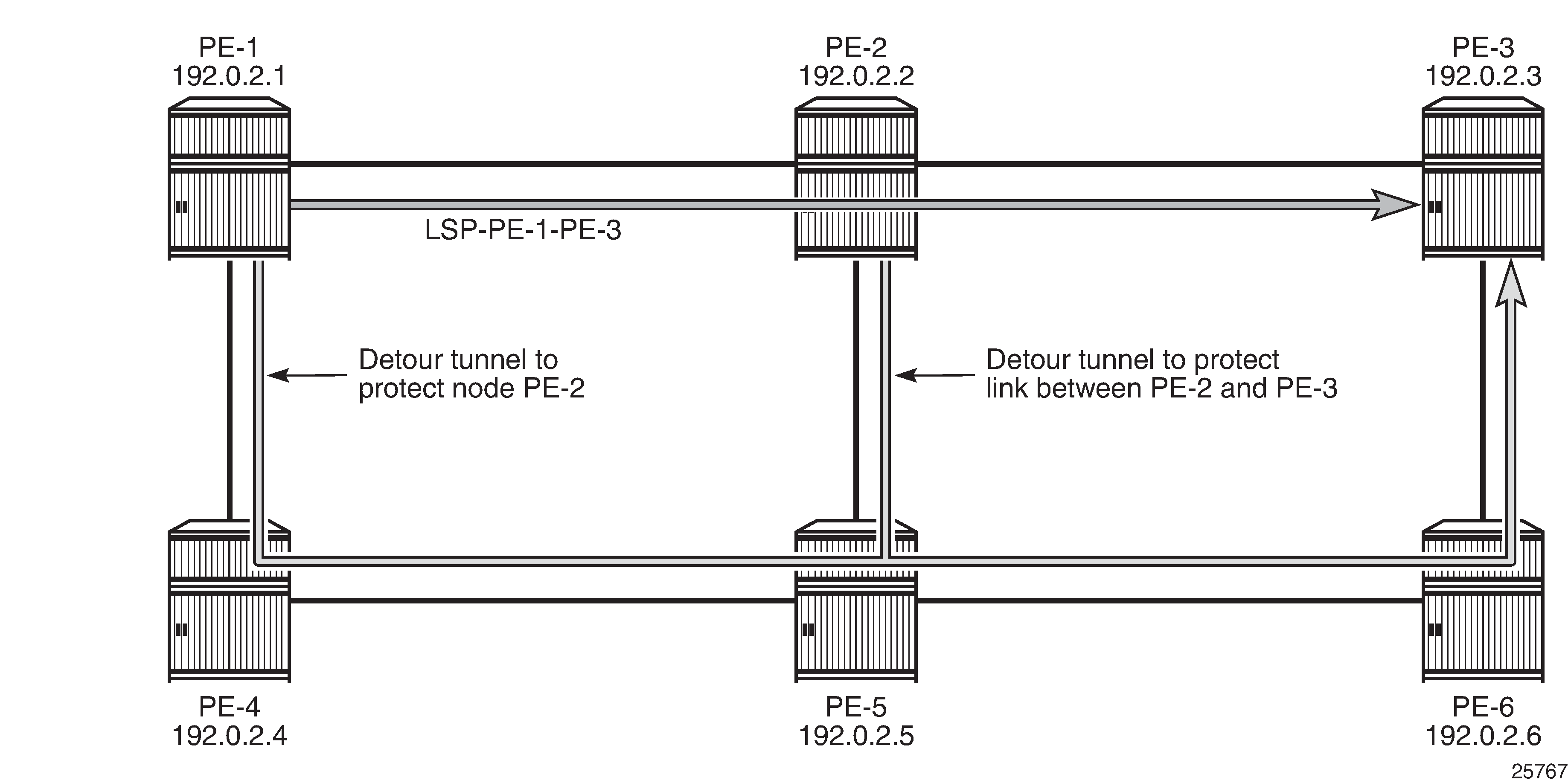
The protection can be seen in the list of actual hops in the path. In PE-1, a detour tunnel for node protection originates (indicated by @ n; see legend) and in PE-2 a detour tunnel for link protection (indicated by @):
[/]
A:admin@PE-1# show router mpls lsp "LSP-PE-1-PE-3" path detail

===============================================================================
MPLS LSP LSP-PE-1-PE-3 Path  (Detail)
===============================================================================
Legend :
    @ - Detour Available              # - Detour In Use
    b - Bandwidth Protected           n - Node Protected
    s - Soft Preemption
    S - Strict                        L - Loose
    A - ABR                           + - Inherited
===============================================================================
-------------------------------------------------------------------------------
LSP LSP-PE-1-PE-3
Path dyn
-------------------------------------------------------------------------------
LSP Name    : LSP-PE-1-PE-3
From             : 192.0.2.1
To               : 192.0.2.3
Admin State      : Up                      Oper State        : Up
Path Name   : dyn
Path LSP ID      : 45064                   Path Type         : Primary
Path Admin       : Up                      Path Oper         : Up
Out Interface    : 1/1/1                   Out Label         : 524287
---snip---

FRR              : Enabled                 Oper FRR          : Enabled
FRR NodeProtect  : Enabled                 Oper FRR NP       : Enabled
FR Hop Limit     : 16                      Oper FRHopLimit   : 16
---snip---

Actual Hops      :
    192.168.12.1(192.0.2.1) @ n                  Record Label        : N/A
 -> 192.168.12.2(192.0.2.2) @                    Record Label        : 524287
 -> 192.168.23.2(192.0.2.3)                      Record Label        : 524287
---snip---

Detour Status    : Standby                 Detour Type       : Originate
Detour Avoid Nod*: 192.0.2.2               Detour Origin     : 192.0.2.1
Setup Priority   : 7                       Hold Priority     : 0
Class Type       : 0
Detour Active Ti*: n/a                     Detour Up Time    : 0d 00:02:55
In Interface     : n/a                     In Label          : n/a
Out Interface    : 1/1/2                   Out Label         : 524287
NextHop          : 192.168.14.2
Explicit Hops    :
    192.168.14.1(S)
 -> 192.168.14.2(S)
 -> 192.168.45.2(S)
 -> 192.168.56.2(S)
 -> 192.168.36.1(S)
===============================================================================
* indicates that the corresponding row element may have been truncated.
The output also contains information about the detour tunnel originating in PE-1 that protects node PE-2. Because the detour tunnel is dedicated for this LSP, that information can be included in the LSP information.
The RSVP detour sessions can be retrieved in the originating, transit, and terminating nodes. On originating node PE-1:
[/]
A:admin@PE-1# show router rsvp session detour

===============================================================================
RSVP Sessions
===============================================================================
RSVP Session Name
    From                To              Tunnel ID   LSP ID       State
-------------------------------------------------------------------------------
LSP-PE-1-PE-3::dyn_detour
192.0.2.1           192.0.2.3           2           45064        Up

-------------------------------------------------------------------------------
Sessions : 1
===============================================================================
In the transit/terminating node PE-5:
[/]
A:admin@PE-5# show router rsvp session detour-transit

===============================================================================
RSVP Sessions
===============================================================================
RSVP Session Name
    From                To              Tunnel ID   LSP ID       State
-------------------------------------------------------------------------------
LSP-PE-1-PE-3::dyn_detour
192.0.2.1           192.0.2.3           2           45064        Up

-------------------------------------------------------------------------------
Sessions : 1
===============================================================================
[/]
A:admin@PE-5# show router rsvp session detour-terminate

===============================================================================
RSVP Sessions
===============================================================================
RSVP Session Name
    From                To              Tunnel ID   LSP ID       State
-------------------------------------------------------------------------------
LSP-PE-1-PE-3::dyn_detour
192.0.2.1           192.0.2.3           2           45064        Up

-------------------------------------------------------------------------------
Sessions : 1
===============================================================================
More detailed information can be retrieved as follows:
[/]
A:admin@PE-5# show router rsvp session detail

===============================================================================
RSVP Sessions (Detailed)
===============================================================================
-------------------------------------------------------------------------------
LSP : LSP-PE-1-PE-3::dyn_detour
-------------------------------------------------------------------------------
From            : 192.0.2.1             To             : 192.0.2.3
Tunnel ID       : 2                     LSP ID         : 45064
Style           : SE                    State          : Up
Session Type    : Transit (Detour)
In Interface    : 1/1/1                 Out Interface  : 1/1/2
In IF Name      : int-PE-5-PE-4
Out IF Name     : int-PE-5-PE-6
In Label        : 524287                Out Label      : 524287
Previous Hop    : 192.168.45.1          Next Hop       : 192.168.56.2
---snip---

-------------------------------------------------------------------------------
LSP : LSP-PE-1-PE-3::dyn_detour
-------------------------------------------------------------------------------
From            : 192.0.2.1             To             : 192.0.2.3
Tunnel ID       : 2                     LSP ID         : 45064
Style           : SE                    State          : Up
Session Type    : Terminate (Detour)
In Interface    : 1/1/3                 Out Interface  : 1/1/2
In IF Name      : int-PE-5-PE-2
Out IF Name     : int-PE-5-PE-6
In Label        : 524286                Out Label      : 524287
Previous Hop    : 192.168.25.1          Next Hop       : 192.168.56.2
---snip---
PE-5 is a transit node for the detour tunnel with previous hop PE-4 and a terminating node for the detour tunnel with previous hop PE-2. In both cases, the next hop is PE-6.
FRR facility
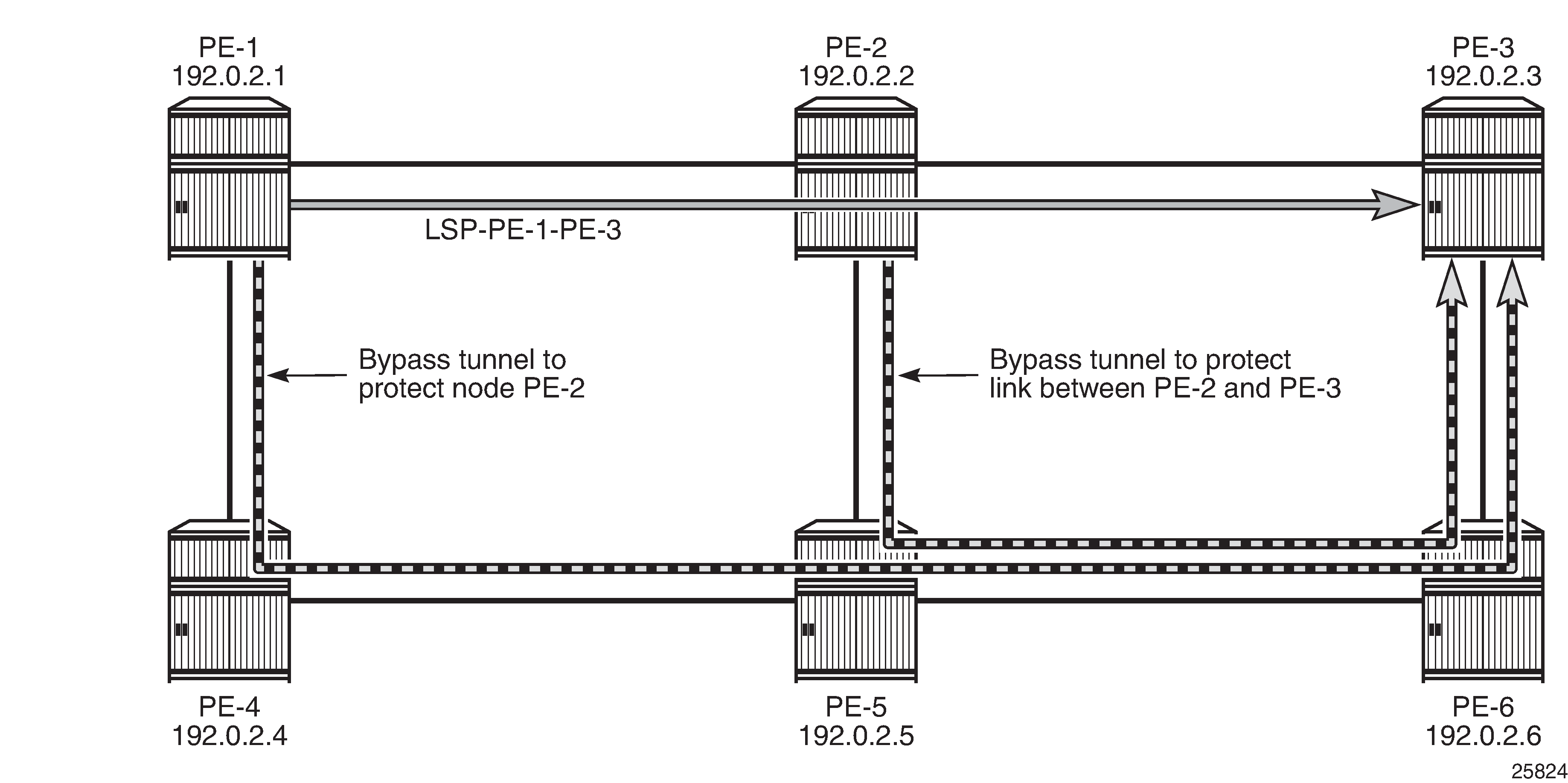
The drawback of FRR one-to-one is that each LSP requires its own detour tunnels to be signaled. FRR facility does not have this issue, because it offers local repair for the next node or the next link that uses bypass tunnels that can be shared by LSPs. FRR facility bypass tunnels terminate in the merge point (MP), which is a hop in the primary path. FRR facility bypass tunnels for link protection terminate in the next hop in the primary path and FRR facility bypass tunnels for node protection terminate in the next hop of that next hop. FRR bypass tunnels are unaware of the final destination of the LSP and need not terminate in the final destination, but in this case they do, because the number of hops in the primary path is limited. FRR facility bypass tunnels shows the FRR facility bypass tunnels for LSP "LSP-PE-1-PE-3":
Fast reroute facility is enabled on LSP "LSP-PE-1-PE-3" as follows:
# on PE-1:
configure {
    router "Base" {
        mpls {
            lsp "LSP-PE-1-PE-3" {
                admin-state enable
                type p2p-rsvp
                to 192.0.2.3
                path-computation-method local-cspf
                fast-reroute {
                    frr-method facility
                }
                primary "dyn" {
                }
The LSP path detail output shows that there is a bypass tunnel available in PE-1 that offers node protection for the next node in the primary path: PE-2. In PE-2, there is a bypass tunnel offering link protection for the next link, which is the link between PE-2 and PE-3; as follows:
[/]
A:admin@PE-1# show router mpls lsp "LSP-PE-1-PE-3" path detail

===============================================================================
MPLS LSP LSP-PE-1-PE-3 Path  (Detail)
===============================================================================
Legend :
    @ - Detour Available              # - Detour In Use
    b - Bandwidth Protected           n - Node Protected
    s - Soft Preemption
    S - Strict                        L - Loose
    A - ABR                           + - Inherited
===============================================================================
-------------------------------------------------------------------------------
LSP LSP-PE-1-PE-3
Path dyn
-------------------------------------------------------------------------------
LSP Name    : LSP-PE-1-PE-3
From             : 192.0.2.1
To               : 192.0.2.3
Admin State      : Up                      Oper State        : Up
Path Name   : dyn
Path LSP ID      : 45064                   Path Type         : Primary
Path Admin       : Up                      Path Oper         : Up
Out Interface    : 1/1/1                   Out Label         : 524287
---snip---

FRR              : Enabled                 Oper FRR          : Enabled
FRR NodeProtect  : Enabled                 Oper FRR NP       : Enabled
FR Hop Limit     : 16                      Oper FRHopLimit   : 16
---snip---

Actual Hops      :
    192.168.12.1(192.0.2.1) @ n                  Record Label        : N/A
 -> 192.168.12.2(192.0.2.2) @                    Record Label        : 524287
 -> 192.168.23.2(192.0.2.3)                      Record Label        : 524287
---snip---

FRR              : Enabled                 Oper FRR          : Enabled
FRR NodeProtect  : Enabled                 Oper FRR NP       : Enabled
FR Hop Limit     : 16                      Oper FRHopLimit   : 16
---snip---
In FRR facility mode, the bypass tunnels are shared. They are not included in the LSP information. The bypass tunnels can be retrieved as follows:
[/]
A:admin@PE-1# show router mpls bypass-tunnel protected-lsp detail

===============================================================================
MPLS Bypass Tunnels (Detail)
===============================================================================
-------------------------------------------------------------------------------
bypass-node192.0.2.2-61441
-------------------------------------------------------------------------------
To             : 192.168.36.1        State               : Up
Out I/F        : 1/1/2               Out Label           : 524287
Up Time        : 0d 00:02:54         Active Time         : n/a
Reserved BW    : 0 Kbps              Protected LSP Count : 1
Type           : Dynamic             Bypass Path Cost    : 40
Setup Priority : 7                   Hold Priority       : 0
Class Type     : 0
Exclude Node   : None                Inter-Area          : False
Computed Hops  :
    192.168.14.1(S)                  Egress Admin Groups : None
 -> 192.168.14.2(S)                  Egress Admin Groups : None
 -> 192.168.45.2(S)                  Egress Admin Groups : None
 -> 192.168.56.2(S)                  Egress Admin Groups : None
 -> 192.168.36.1(S)                  Egress Admin Groups : None
Actual Hops    :
    192.168.14.1(192.0.2.1)          Record Label        : N/A
 -> 192.168.14.2(192.0.2.4)          Record Label        : 524287
 -> 192.168.45.2(192.0.2.5)          Record Label        : 524286
 -> 192.168.56.2(192.0.2.6)          Record Label        : 524286
 -> 192.168.36.1(192.0.2.3)          Record Label        : 524285
Last Resignal  :
Attempted At   : n/a                 Resignal Reason     : n/a
Resignal Status: n/a                 Reason              : n/a

Protected LSPs -
LSP Name       : LSP-PE-1-PE-3::dyn
From           : 192.0.2.1           To                  : 192.0.2.3
Avoid Node/Hop : 192.0.2.2           Downstream Label    : 524287
Bandwidth      : 0 Kbps

===============================================================================
This is the bypass tunnel that originates in PE-1 to protect (avoid) PE-2. In this example, there is only one LSP protected by this bypass tunnel, but the list of protected LSPs can be longer. The same command can be launched on PE-2, where a bypass tunnel originates that protects the link between PE-2 and PE-3.
The RSVP sessions can be displayed as follows:
[/]
A:admin@PE-3# show router rsvp session

===============================================================================
RSVP Sessions
===============================================================================
RSVP Session Name
    From                To              Tunnel ID   LSP ID       State
-------------------------------------------------------------------------------
LSP-PE-1-PE-3::dyn
192.0.2.1           192.0.2.3           2           45066        Up

bypass-link192.168.23.2-61441
192.0.2.2           192.168.36.1        61441       2            Up

bypass-node192.0.2.2-61441
192.0.2.1           192.168.36.1        61441       2            Up

-------------------------------------------------------------------------------
Sessions : 3
===============================================================================
In PE-3, there is an RSVP session for the regular LSP and two bypass tunnels. In this case, the bypass tunnels all go to PE-3, which is the terminating node for the LSP, but that need not be the case. All bypass tunnels are signaled from the point of local repair to the merge point on the LSP path.
To force a FRR facility switchover to a bypass tunnel, a failure is simulated by disabling port 1/1/1 on PE-2, as follows:
# on PE-2:
configure {
    port 1/1/1 {
        admin-state disable
The detailed output for the LSP path on PE-1 shows that the tunnel is locally repaired.
[/]
A:admin@PE-1# show router mpls lsp "LSP-PE-1-PE-3" path detail

===============================================================================
MPLS LSP LSP-PE-1-PE-3 Path  (Detail)
===============================================================================
Legend :
    @ - Detour Available              # - Detour In Use
    b - Bandwidth Protected           n - Node Protected
    s - Soft Preemption
    S - Strict                        L - Loose
    A - ABR                           + - Inherited
===============================================================================
-------------------------------------------------------------------------------
LSP LSP-PE-1-PE-3
Path dyn
-------------------------------------------------------------------------------
LSP Name    : LSP-PE-1-PE-3
From             : 192.0.2.1
To               : 192.0.2.3
Admin State      : Up                      Oper State        : Up
Path Name   : dyn
Path LSP ID      : 45066                   Path Type         : Primary
Path Admin       : Up                      Path Oper         : Up
Out Interface    : 1/1/1                   Out Label         : 524287
---snip---

Adaptive         : Enabled                 Oper Metric       : 20
Preference       : n/a
Path Trans       : 8                       CSPF Queries      : 6
Failure Code     : tunnelLocallyRepaired
Failure Node : 192.0.2.2
Explicit Hops    :
    No Hops Specified
Actual Hops      :
    192.168.12.1(192.0.2.1) @ n                  Record Label        : N/A
 -> 192.168.12.2(192.0.2.2) @ #                  Record Label        : 524287
 -> 192.168.36.1(192.0.2.3)                      Record Label        : 524287
---snip---
The failure code is tunnelLocallyRepaired and next to the actual hop 192.168.12.2 (PE-2), the symbol # indicates that the detour is in use.
FRR facility without node protection
Node protection is by default enabled, but can be disabled as follows:
# on PE-1:
configure {
    router "Base" {
        mpls {
            lsp "LSP-PE-1-PE-3" {
                admin-state enable
                type p2p-rsvp
                to 192.0.2.3
                fast-reroute {
                    frr-method facility
                    node-protect false
                }
                primary "dyn" {
                }
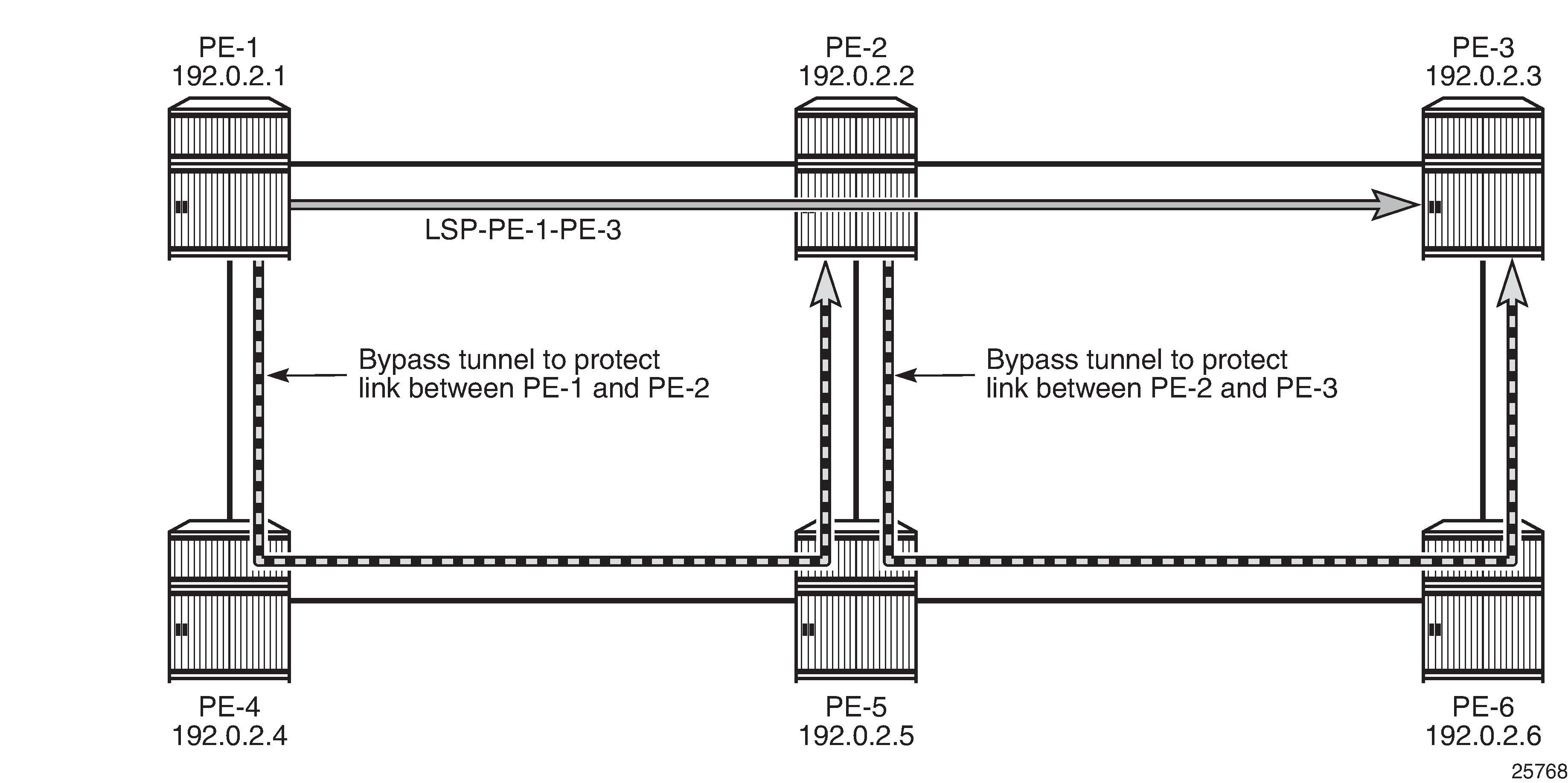
As a result, there is only link protection. The bypass tunnels from PE-1 and PE-2 terminate in the next hop in the primary path, as shown in FRR facility without node protection:
The LSP path detail output shows that there is no node protection:
[/]
A:admin@PE-1# show router mpls lsp "LSP-PE-1-PE-3" path detail

===============================================================================
MPLS LSP LSP-PE-1-PE-3 Path  (Detail)
===============================================================================
Legend :
    @ - Detour Available              # - Detour In Use
    b - Bandwidth Protected           n - Node Protected
    s - Soft Preemption
    S - Strict                        L - Loose
    A - ABR                           + - Inherited
===============================================================================
-------------------------------------------------------------------------------
LSP LSP-PE-1-PE-3
Path dyn
-------------------------------------------------------------------------------
LSP Name    : LSP-PE-1-PE-3
From             : 192.0.2.1
To               : 192.0.2.3
Admin State      : Up                      Oper State        : Up
Path Name   : dyn
Path LSP ID      : 45070                   Path Type         : Primary
Path Admin       : Up                      Path Oper         : Up
Out Interface    : 1/1/1                   Out Label         : 524283
---snip---

FRR              : Enabled                 Oper FRR          : Enabled
FRR NodeProtect  : Disabled                Oper FRR NP       : Disabled
---snip---

Actual Hops      :
    192.168.12.1(192.0.2.1) @                    Record Label        : N/A
 -> 192.168.12.2(192.0.2.2) @                    Record Label        : 524283
 -> 192.168.23.2(192.0.2.3)                      Record Label        : 524285
---snip---
The bypass tunnel originating in PE-1 is now terminating in PE-2 instead of PE-3; as follows:
[/]
A:admin@PE-1# show router mpls bypass-tunnel protected-lsp detail

===============================================================================
MPLS Bypass Tunnels (Detail)
===============================================================================
-------------------------------------------------------------------------------
bypass-link192.168.12.2-61443
-------------------------------------------------------------------------------
To             : 192.168.25.1        State               : Up
Out I/F        : 1/1/2               Out Label           : 524287
Up Time        : 0d 00:02:14         Active Time         : n/a
Reserved BW    : 0 Kbps              Protected LSP Count : 1
Type           : Dynamic             Bypass Path Cost    : 30
Setup Priority : 7                   Hold Priority       : 0
Class Type     : 0
Exclude Node   : None                Inter-Area          : False
Computed Hops  :
    192.168.14.1(S)                  Egress Admin Groups : None
 -> 192.168.14.2(S)                  Egress Admin Groups : None
 -> 192.168.45.2(S)                  Egress Admin Groups : None
 -> 192.168.25.1(S)                  Egress Admin Groups : None
Actual Hops    :
    192.168.14.1(192.0.2.1)          Record Label        : N/A
 -> 192.168.14.2(192.0.2.4)          Record Label        : 524287
 -> 192.168.45.2(192.0.2.5)          Record Label        : 524282
 -> 192.168.25.1(192.0.2.2)          Record Label        : 524282
Last Resignal  :
Attempted At   : n/a                 Resignal Reason     : n/a
Resignal Status: n/a                 Reason              : n/a
Protected LSPs -
LSP Name       : LSP-PE-1-PE-3::dyn
From           : 192.0.2.1           To                  : 192.0.2.3
Avoid Node/Hop : 192.168.12.2        Downstream Label    : 524283
Bandwidth      : 0 Kbps

===============================================================================
In the remainder of this chapter, this LSP is no longer used. Therefore, the LSP is disabled, as follows:
# on PE-1:
configure {
    router "Base" {
        mpls {
            lsp "LSP-PE-1-PE-3" {
                admin-state disable
Administrative groups for RSVP-TE LSPs
Administrative groups (link-coloring) can be used to calculate a path with the restriction to only include links of a particular admin group (color) or to exclude links of a particular admin group. Paths can be disjointed from each other, without the need for an explicit hops list.
Two admin groups are configured on all nodes; as follows:
# on all nodes:
configure {
    routing-options {
        if-attribute {
            admin-group "blue" {
                value 1
            }
            admin-group "red" {
                value 0
            }
        }
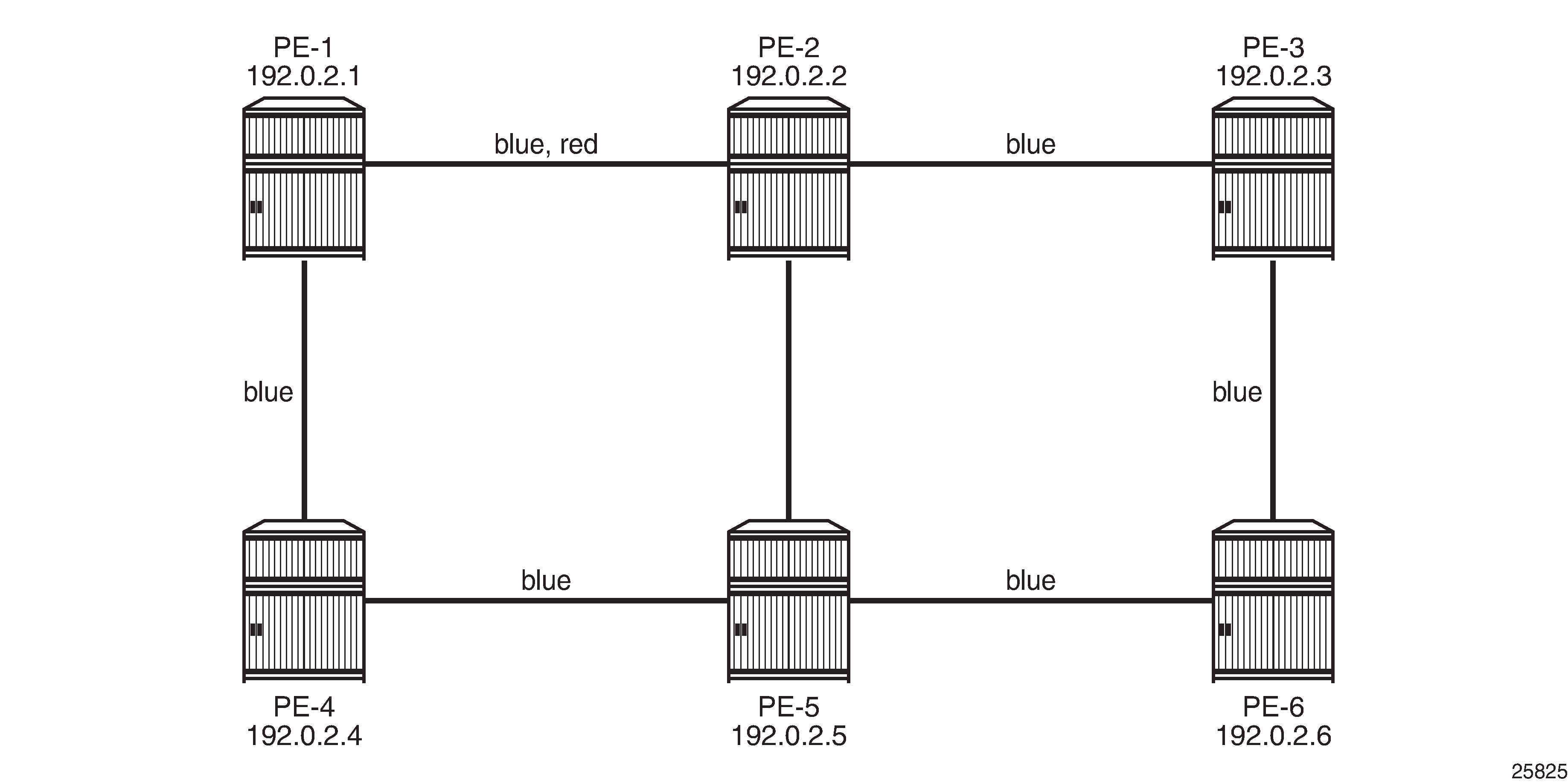
Admin group "blue" is assigned to all MPLS interfaces, except for the link between PE-2 and PE-5 while admin group "red" is only assigned to the link between PE-1 and PE-2; see Admin groups 'blue' and 'red':
The admin groups are assigned to the MPLS interfaces as follows:
# on PE-1:
configure {
    router "Base" {
        mpls {
            interface "int-PE-1-PE-2" {
                admin-group ["blue" "red"]
            }
            interface "int-PE-1-PE-4" {
                admin-group ["blue"]
            }
The configuration on the other nodes is similar.
To ensure that FRR bypass tunnels will adhere to the same admin group constraints as defined in the LSP, the following is configured on all nodes. It is required on all Points of Local Repair (PLRs):
# on all nodes (at least on all PLRs):
configure {
    router "Base" {
        mpls {
            admin-group-frr true
LSP includes admin group 'blue'
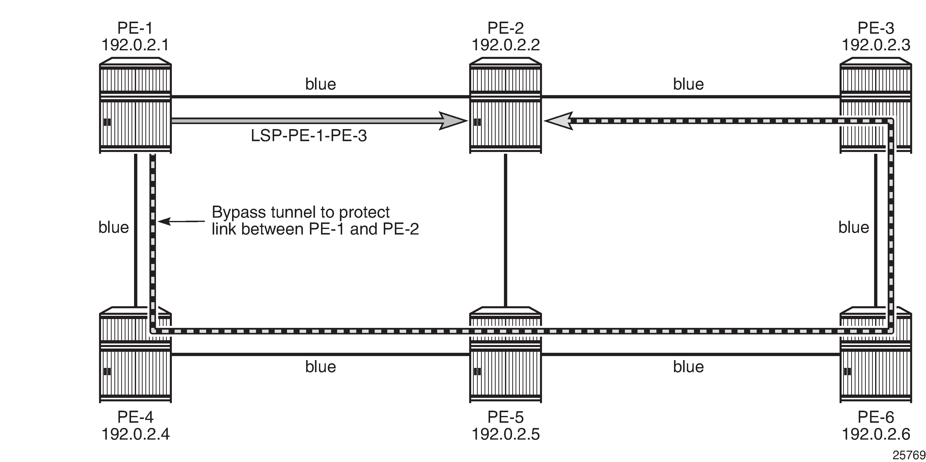
LSP "LSP-PE-1-PE-2" is created on PE-1 with a dynamic primary path. FRR facility is enabled. The LSP includes admin group blue and both the primary path as the bypass tunnel must use links in admin group "blue" (propagate-admin-group). Admin-group-frr is enabled in the mpls context, to ensure that the admin group restriction is respected for FRR.
# on PE-1:
configure {
    router "Base" {
        mpls {
            admin-group-frr true
            lsp "LSP-PE-1-PE-2" {
                admin-state enable
                type p2p-rsvp
                to 192.0.2.2
                propagate-admin-group true
                path-computation-method local-cspf
                include-admin-group ["blue"]
                fast-reroute {
                    propagate-admin-group true
                    frr-method facility
                }
                primary "dyn" {
                }
The bypass tunnel cannot include the link between PE-2 and PE-5, because that link does not belong to admin group "blue". The LSP and its bypass tunnel are shown in LSP and bypass within admin group 'blue':
The LSP path detailed information is as follows:
[/]
A:admin@PE-1# show router mpls lsp "LSP-PE-1-PE-2" path detail

===============================================================================
MPLS LSP LSP-PE-1-PE-2 Path  (Detail)
===============================================================================
Legend :
    @ - Detour Available              # - Detour In Use
    b - Bandwidth Protected           n - Node Protected
    s - Soft Preemption
    S - Strict                        L - Loose
    A - ABR                           + - Inherited
===============================================================================
-------------------------------------------------------------------------------
LSP LSP-PE-1-PE-2
Path dyn
-------------------------------------------------------------------------------
LSP Name    : LSP-PE-1-PE-2
From             : 192.0.2.1
To               : 192.0.2.2
Admin State      : Up                      Oper State        : Up
Path Name   : dyn
Path LSP ID      : 64000                   Path Type         : Primary
Path Admin       : Up                      Path Oper         : Up
Out Interface    : 1/1/1                   Out Label         : 524287
---snip---

FRR              : Enabled                 Oper FRR          : Enabled
FRR NodeProtect  : Enabled                 Oper FRR NP       : Enabled
FR Hop Limit     : 16                      Oper FRHopLimit   : 16
FR Prop Admin Gr*: Enabled                 Oper FRPropAdmGrp : Enabled
Propagate Adm Grp: Enabled                 Oper Prop Adm Grp : Enabled
---snip---

Include Groups   :                         Oper IncludeGroups:
blue                                           blue
Exclude Groups   :                         Oper ExcludeGroups:
None                                           None
---snip---

Actual Hops      :
    192.168.12.1(192.0.2.1) @                    Record Label        : N/A
 -> 192.168.12.2(192.0.2.2)                      Record Label        : 524287
---snip---
There is a bypass tunnel originating in PE-1 that offers protection for the link between PE-1 and PE-2. More information about this bypass tunnel can be retrieved as follows:
[/]
A:admin@PE-1# show router mpls bypass-tunnel protected-lsp detail

===============================================================================
MPLS Bypass Tunnels (Detail)
===============================================================================
-------------------------------------------------------------------------------
bypass-link192.168.12.2-61444
-------------------------------------------------------------------------------
To             : 192.168.23.1        State               : Up
Out I/F        : 1/1/2               Out Label           : 524287
Up Time        : 0d 00:01:20         Active Time         : n/a
Reserved BW    : 0 Kbps              Protected LSP Count : 1
Type           : Dynamic             Bypass Path Cost    : 50
Setup Priority : 7                   Hold Priority       : 0
Class Type     : 0
Exclude Node   : None                Inter-Area          : False
Computed Hops  :
    192.168.14.1(S)                  Egress Admin Groups :
                                     blue
 -> 192.168.14.2(S)                  Egress Admin Groups :
                                     blue
 -> 192.168.45.2(S)                  Egress Admin Groups :
                                     blue
 -> 192.168.56.2(S)                  Egress Admin Groups :
                                     blue
 -> 192.168.36.1(S)                  Egress Admin Groups :
                                     blue
 -> 192.168.23.1(S)                  Egress Admin Groups : None
Actual Hops    :
    192.168.14.1(192.0.2.1)          Record Label        : N/A
 -> 192.168.14.2(192.0.2.4)          Record Label        : 524287
 -> 192.168.45.2(192.0.2.5)          Record Label        : 524287
 -> 192.168.56.2(192.0.2.6)          Record Label        : 524287
 -> 192.168.36.1(192.0.2.3)          Record Label        : 524287
 -> 192.168.23.1(192.0.2.2)          Record Label        : 524286
Last Resignal  :
Attempted At   : n/a                 Resignal Reason     : n/a
Resignal Status: n/a                 Reason              : n/a

Protected LSPs -
LSP Name       : LSP-PE-1-PE-2::dyn
From           : 192.0.2.1           To                  : 192.0.2.2
Avoid Node/Hop : 192.168.12.2        Downstream Label    : 524287
Bandwidth      : 0 Kbps

===============================================================================
All egress links are in admin group blue on the originating and transit nodes.
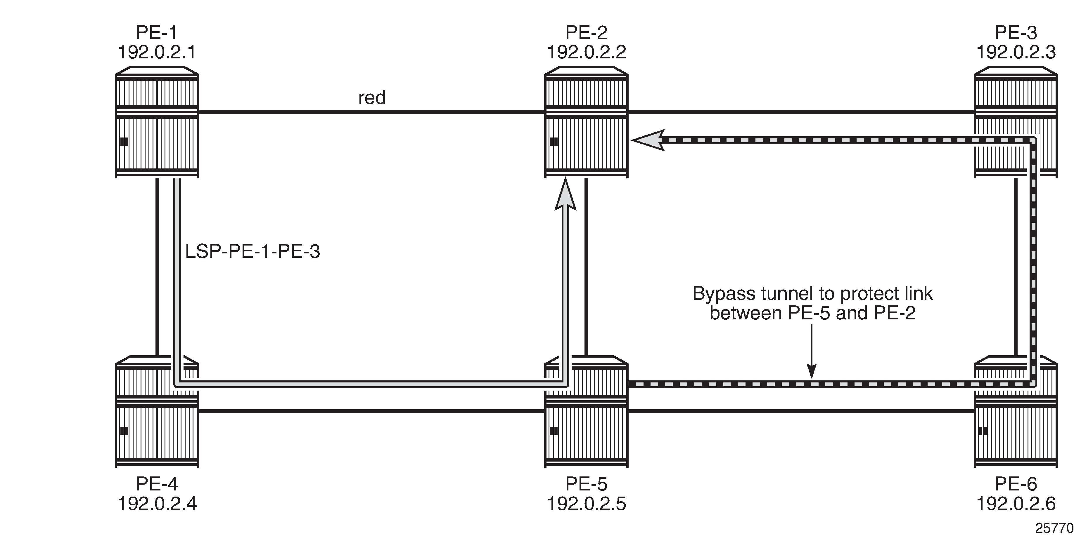
LSP excludes admin group 'red'
The LSP is reconfigured: instead of including admin group 'blue', it will exclude admin group 'red'. Nothing is changed to the configuration of FRR.
The MPLS configuration is modified as follows:
# on PE-1:
configure {
    router "Base" {
        mpls {
            lsp "LSP-PE-1-PE-2" {
                delete include-admin-group ["blue"]
                exclude-admin-group ["red"]
The LSP cannot use the red link between PE-1 and PE-2. The path that avoids the red link, is from PE-1 via PE-4 and PE-5 to PE-2. On all PLRs, admin-group-frr is configured, which implies that the originating FRR bypass tunnels need to respect the admin-group constraint of the LSP. There can be no node protection for PE-4 or PE-5 without using the red link between PE-1 and PE-2. The only link that can be protected without using the red link between PE-1 and PE-2, is the link between PE-5 and PE-2. The LSP and the FRR bypass tunnel are shown in LSP and FRR bypass tunnel excluding admin group 'red':
The LSP path can be verified as follows:
[/]
A:admin@PE-1# show router mpls lsp "LSP-PE-1-PE-2" path detail

===============================================================================
MPLS LSP LSP-PE-1-PE-2 Path  (Detail)
===============================================================================
Legend :
    @ - Detour Available              # - Detour In Use
    b - Bandwidth Protected           n - Node Protected
    s - Soft Preemption
    S - Strict                        L - Loose
    A - ABR                           + - Inherited
===============================================================================
-------------------------------------------------------------------------------
LSP LSP-PE-1-PE-2
Path dyn
-------------------------------------------------------------------------------
LSP Name    : LSP-PE-1-PE-2
From             : 192.0.2.1
To               : 192.0.2.2
Admin State      : Up                      Oper State        : Up
Path Name   : dyn
Path LSP ID      : 64002                   Path Type         : Primary
Path Admin       : Up                      Path Oper         : Up
Out Interface    : 1/1/2                   Out Label         : 524286
---snip---

Include Groups   :                         Oper IncludeGroups:
None                                           None
Exclude Groups   :                         Oper ExcludeGroups:
red                                            red
---snip---

Actual Hops      :
    192.168.14.1(192.0.2.1)                      Record Label        : N/A
 -> 192.168.14.2(192.0.2.4)                      Record Label        : 524286
 -> 192.168.45.2(192.0.2.5) @                    Record Label        : 524286
 -> 192.168.25.1(192.0.2.2)                      Record Label        : 524285
---snip---
There is only link protection for the link from PE-5 to PE-2. The bypass tunnel originates in PE-5 and has no links belonging to admin group 'red':
[/]
A:admin@PE-5# show router mpls bypass-tunnel protected-lsp detail

===============================================================================
MPLS Bypass Tunnels (Detail)
===============================================================================
-------------------------------------------------------------------------------
bypass-link192.168.25.1-62074
-------------------------------------------------------------------------------
To             : 192.168.23.1        State               : Up
Out I/F        : 1/1/2               Out Label           : 524286
Up Time        : 0d 00:04:38         Active Time         : n/a
Reserved BW    : 0 Kbps              Protected LSP Count : 1
Type           : Dynamic             Bypass Path Cost    : 30
Setup Priority : 7                   Hold Priority       : 0
Class Type     : 0
Exclude Node   : None                Inter-Area          : False
Computed Hops  :
    192.168.56.1(S)                  Egress Admin Groups :
                                     blue
 -> 192.168.56.2(S)                  Egress Admin Groups :
                                     blue
 -> 192.168.36.1(S)                  Egress Admin Groups :
                                     blue
 -> 192.168.23.1(S)                  Egress Admin Groups : None
Actual Hops    :
    192.168.56.1(192.0.2.5)          Record Label        : N/A
 -> 192.168.56.2(192.0.2.6)          Record Label        : 524286
 -> 192.168.36.1(192.0.2.3)          Record Label        : 524286
 -> 192.168.23.1(192.0.2.2)          Record Label        : 524284
Last Resignal  :
Attempted At   : n/a                 Resignal Reason     : n/a
Resignal Status: n/a                 Reason              : n/a

Protected LSPs -
LSP Name       : LSP-PE-1-PE-2::dyn
From           : 192.0.2.1           To                  : 192.0.2.2
Avoid Node/Hop : 192.168.25.1        Downstream Label    : 524287
Bandwidth      : 0 Kbps

===============================================================================
This configuration is preserved for the following example.
Hop limit for RSVP-TE LSPs
Another constraint to influence the path selection, is hop limit. This can be configured on the LSP, on a secondary path, or on FRR in case the path should not contain too many hops. In this example, it will be configured on the LSP and later also for FRR on that LSP. By default, the LSP hop limit is 255, but it can be configured as follows:
# on PE-1:
configure {
    router "Base" {
        mpls {
            lsp "LSP-PE-1-PE-2" {
                hop-limit 5
This hop limit of 5 is enough for the path via PE-4 and PE-5, but it will not be sufficient when the link between PE-2 and PE-5 is down:
# on PE-5:
configure {
    port 1/1/3 {
        admin-state disable
In this case, the only possible path that excludes the 'red' link between PE-1 and PE-2, has to go to PE-2 via PE-4, PE-5, PE-6, and PE-3. There are too many hops. The FRR bypass tunnel can do a local repair, but no new LSP path can be signaled, with failure code: noCspfRouteToDestination:
[/]
A:admin@PE-1# show router mpls lsp "LSP-PE-1-PE-2" path detail

===============================================================================
MPLS LSP LSP-PE-1-PE-2 Path  (Detail)
===============================================================================
Legend :
    @ - Detour Available              # - Detour In Use
    b - Bandwidth Protected           n - Node Protected
    s - Soft Preemption
    S - Strict                        L - Loose
    A - ABR                           + - Inherited
===============================================================================
-------------------------------------------------------------------------------
LSP LSP-PE-1-PE-2
Path dyn
-------------------------------------------------------------------------------
LSP Name    : LSP-PE-1-PE-2
From             : 192.0.2.1
To               : 192.0.2.2
Admin State      : Up                      Oper State        : Up
Path Name   : dyn
Path LSP ID      : 64004                   Path Type         : Primary
Path Admin       : Up                      Path Oper         : Up
Out Interface    : 1/1/2                   Out Label         : 524287
---snip---

Include Groups   :                         Oper IncludeGroups:
None                                           None
Exclude Groups   :                         Oper ExcludeGroups:
red                                            red

Adaptive         : Enabled                 Oper Metric       : 30
Preference       : n/a
Path Trans       : 3                       CSPF Queries      : 4
Failure Code     : tunnelLocallyRepaired
Failure Node : 192.0.2.5
Explicit Hops    :
    No Hops Specified
Actual Hops      :
    192.168.14.1(192.0.2.1)                      Record Label        : N/A
 -> 192.168.14.2(192.0.2.4)                      Record Label        : 524287
 -> 192.168.45.2(192.0.2.5) @ #                  Record Label        : 524287
 -> 192.168.25.1(192.0.2.2)                      Record Label        : 524287
---snip---

In Prog MBB :
 MBB Type        : GlobalRevert            Next Retry In     : 24 sec
 Started At      : 02/13/2021 17:32:35     Retry Attempt     : 1
 Failure Code    : noCspfRouteToDestinatio Failure Node      : 192.0.2.1
                   n
 Signaled BW     : 0 Mbps
===============================================================================
* indicates that the corresponding row element may have been truncated.
FRR tunnels also have a hop limit. The FRR hop limit is by default 16, but can be configured as follows:
# on PE-1:
configure {
    router "Base" {
        mpls {
            lsp "LSP-PE-1-PE-2" {
                fast-reroute {
                    hop-limit 3
                }
When the LSP is recalculated, it is impossible to establish the primary path with a hop limit of 5 and it is also impossible to establish a bypass tunnel protecting the link between PE-5 and PE-2 when the FRR hop limit is 3. The LSP will remain operationally down with failure code: noCspfRouteToDestination:
[/]
A:admin@PE-1# show router mpls lsp "LSP-PE-1-PE-2" path detail

===============================================================================
MPLS LSP LSP-PE-1-PE-2 Path  (Detail)
===============================================================================
Legend :
    @ - Detour Available              # - Detour In Use
    b - Bandwidth Protected           n - Node Protected
    s - Soft Preemption
    S - Strict                        L - Loose
    A - ABR                           + - Inherited
===============================================================================
-------------------------------------------------------------------------------
LSP LSP-PE-1-PE-2
Path dyn
-------------------------------------------------------------------------------
LSP Name    : LSP-PE-1-PE-2
From             : 192.0.2.1
To               : 192.0.2.2
Admin State      : Up                      Oper State        : Down
Path Name   : dyn
Path LSP ID      : 64008                   Path Type         : Primary
Path Admin       : Up                      Path Oper         : Down
Out Interface    : n/a                     Out Label         : n/a
Path Up Time     : 0d 00:00:00             Path Down Time    : 0d 00:00:56
---snip---

FRR              : Enabled                 Oper FRR          : N/A
FRR NodeProtect  : Enabled                 Oper FRR NP       : N/A
FR Hop Limit     : 3                       Oper FRHopLimit   : N/A
FR Prop Admin Gr*: Enabled                 Oper FRPropAdmGrp : N/A
Propagate Adm Grp: Enabled                 Oper Prop Adm Grp : N/A
---snip---

Neg MTU          : 0                       Oper MTU          : N/A
Bandwidth        : No Reservation          Oper Bandwidth    : N/A
Hop Limit        : 5                       Oper HopLimit     : N/A
---snip---

Include Groups   :                         Oper IncludeGroups:
None                                           N/A
Exclude Groups   :                         Oper ExcludeGroups:
red                                            N/A
---snip---

Failure Code     : noCspfRouteToDestination
Failure Node : 192.0.2.1
Explicit Hops    :
    No Hops Specified
Actual Hops      :
    No Hops Specified
---snip---
For the remainder of the examples, FRR is disabled and the hop limit is restored to the default value, which is 255:
# on PE-1:
configure {
    router "Base" {
        mpls {
            lsp "LSP-PE-1-PE-2" {
                delete hop-limit
                delete fast-reroute
On PE-5, port 1/1/3 is enabled, as follows:
# on PE-5:
configure {
    port 1/1/3 {
        admin-state enable
Manual resignal
Instead of waiting for the resignal timer to expire, one can manually trigger the resignal process.
The command to resignal the path "dyn" of LSP "LSP-PE-1-PE-2":
[/]
A:admin@PE-1# tools perform router mpls resignal lsp "LSP-PE-1-PE-2" path "dyn"
The command to resignal all RSVP LSPs originating at node PE-1:
[/]
A:admin@PE-1# tools perform router mpls resignal delay 0
WARNING: CLI #2006: Warning while processing command - WARNING: CLI Delay will not be in effect, configure resignal-timer at config>router>mpls>resignal-timer .
The preceding command overrules the resignal timer in the mpls context, so it can only be launched after the resignal timer is configured.
[ex:configure router "Base" mpls]
A:admin@PE-1# resignal-timer ?

 resignal-timer <number>
 <number>  - <30..10080>  - minutes

    Resignal timer for RSVP LSPs
The configuration timer is configured to 30 minutes as follows:
# on PE-1:
configure {
    router "Base" {
        mpls {
            resignal-timer 30
Whenever an LSP is resignaled, the resignal timer is restarted.
LSP OAM
The LSP diagnostics are modeled after ICMP echo request/reply which provides a mechanism to detect data plane failures in MPLS LSPs. For a given FEC, LSP ping verifies whether the packet reaches the egress label edge router (LER). The following OAM commands are in classic CLI.
[/]
A:admin@PE-1# //
INFO: CLI #2051: Switching to the classic CLI engine
A:PE-1# oam lsp-ping "LSP-PE-1-PE-2"
LSP-PING LSP-PE-1-PE-2: 92 bytes MPLS payload
Seq=1, send from intf int-PE-1-PE-4, reply from 192.0.2.2
       udp-data-len=32 ttl=255 rtt=3.71ms rc=3 (EgressRtr)

---- LSP LSP-PE-1-PE-2 PING Statistics ----
1 packets sent, 1 packets received, 0.00% packet loss
round-trip min = 3.71ms, avg = 3.71ms, max = 3.71ms, stddev = 0.000ms
In LSP traceroute mode, the packet is sent to the control plane of each transit label switched router (LSR) which performs various checks to see if it is actually a transit LSR for the path.
A:PE-1# oam lsp-trace "LSP-PE-1-PE-2"
lsp-trace to LSP-PE-1-PE-2: 0 hops min, 0 hops max, 116 byte packets
1  192.0.2.4  rtt=2.60ms rc=8(DSRtrMatchLabel) rsc=1
2  192.0.2.5  rtt=3.82ms rc=8(DSRtrMatchLabel) rsc=1
3  192.0.2.2  rtt=3.54ms rc=3(EgressRtr) rsc=1
A:PE-1# oam lsp-trace "LSP-PE-1-PE-2" detail
lsp-trace to LSP-PE-1-PE-2: 0 hops min, 0 hops max, 116 byte packets
1  192.0.2.4  rtt=2.30ms rc=8(DSRtrMatchLabel) rsc=1
     DS 1: ipaddr=192.168.45.2 ifaddr=192.168.45.2 iftype=ipv4Numbered MRU=1564
           label[1]=524286 protocol=4(RSVP-TE)
2  192.0.2.5  rtt=3.70ms rc=8(DSRtrMatchLabel) rsc=1
     DS 1: ipaddr=192.168.25.1 ifaddr=192.168.25.1 iftype=ipv4Numbered MRU=1564
           label[1]=524286 protocol=4(RSVP-TE)
3  192.0.2.2  rtt=3.84ms rc=3(EgressRtr) rsc=1
RSVP LSP statistics
Statistics can be collected for RSVP LSPs. For each accounting record, a file ID is configured; as follows:
# on PE-1:
configure {
    log {
        file 2 {
            rollover 5
            retention 1
            compact-flash-location {
                primary cf1
            }
        }
An accounting policy is configured for each record type; as follows:
# on PE-1:
configure {
    log {
        accounting-policy 2 {
            admin-state enable
            record combined-mpls-lsp-ingress
            destination {
                file 2
            }
        }
The collection of statistics is enabled in the mpls context as follows:
# on PE-1:
configure {
    router "Base" {
        mpls {
            ingress-statistics {
                lsp sender 192.0.2.1 lsp-name "LSP-PE-1-PE-2" {
                    admin-state enable
                    collect-stats true
                    accounting-policy 2
                }
            }
To display the statistics, the following options are available for lsp-ingress-stats:
[/]
A:admin@PE-1# show router mpls lsp-ingress-stats ?

 lsp-ingress-stats [type <keyword>] [active]
 lsp-ingress-stats lsp <string> sender <ipv4 address>
 lsp-ingress-stats [sender <ipv4 address>] [type <keyword>] [active] template-match
  SessionNameString <string>

 SessionNameString     - [Max 64 chars]
 active                - match on all stats enabled lsp
 lsp                   - max 64 chars
 sender                - ipv4 address '<d.d.d.d>'
 template-match        - match on p2p/p2mp stats template
 type                  - p2p|p2mp
The following command retrieves the LSP ingress statistics for LSP "LPS-PE-1-PE-2" with sender 192.0.2.1:
[/]
A:admin@ PE-1# show router mpls lsp-ingress-stats lsp "LSP-PE-1-PE-2"
                                                              sender 192.0.2.1

===============================================================================
MPLS LSP Ingress Statistics
===============================================================================
-------------------------------------------------------------------------------
LSP Name      : LSP-PE-1-PE-2
Sender        : 192.0.2.1
-------------------------------------------------------------------------------
Collect Stats    : Enabled              Accting Plcy.    : 2
Adm State        : Up                   PSB Match        : False
FC BE
InProf Pkts      : 0                    OutProf Pkts     : 0
InProf Octets    : 0                    OutProf Octets   : 0
FC L2
InProf Pkts      : 0                    OutProf Pkts     : 0
InProf Octets    : 0                    OutProf Octets   : 0
FC AF
InProf Pkts      : 0                    OutProf Pkts     : 0
InProf Octets    : 0                    OutProf Octets   : 0
FC L1
InProf Pkts      : 0                    OutProf Pkts     : 0
InProf Octets    : 0                    OutProf Octets   : 0
FC H2
InProf Pkts      : 0                    OutProf Pkts     : 0
InProf Octets    : 0                    OutProf Octets   : 0
FC EF
InProf Pkts      : 0                    OutProf Pkts     : 0
InProf Octets    : 0                    OutProf Octets   : 0
FC H1
InProf Pkts      : 0                    OutProf Pkts     : 0
InProf Octets    : 0                    OutProf Octets   : 0
FC NC
InProf Pkts      : 0                    OutProf Pkts     : 0
InProf Octets    : 0                    OutProf Octets   : 0

Aggregate Pkts   : 0                    Aggregate Octets : 0
===============================================================================
Statistics can be cleared as follows:
[clear router mpls]
A:admin@PE-1# lsp-ingress-stats 192.0.2.1 lsp "LSP-PE-1-PE-2"
[clear router mpls]
A:admin@PE-1# lsp-ingress-stats
Debug
A wide range of debug tools are available which can be tuned to the specific information of importance for a certain troubleshooting task. These tools are in classic CLI. In the debug router mpls context, the LSP object to trace or monitor can be selected by the following parameters:
-
LSP name
-
Source address of the LSP (the from parameter in the LSP definition)
-
Termination point of the LSP (the to parameter in the LSP definition)
-
Tunnel ID of the LSP
-
LSP ID
A:PE-1# debug router rsvp ?
  - no rsvp
  - rsvp [lsp name>] [sender <sender-address>] [endpoint <endpoint-address>]
         [tunnel-id <tunnel-id>] [lsp-id <lsp-id>] [interface <ip-int-name>]

 <name>               : [160 chars max]
 <sender-address>     : a.b.c.d
 <endpoint-address>   : a.b.c.d
 <tunnel-id>          : [0..4294967295]
 <lsp-id>             : [1..65535]
 <ip-int-name>        : [32 chars max]


 [no] event           + Enable/disable debugging for specific RSVP events
 [no] packet          + Enable/disable debugging for specific RSVP packets
A:PE-1# debug router mpls ?
  - mpls [lsp <name>] [sender <ip-address|ipv6-address>] [endpoint <ip-address|
    ipv6-address>] [tunnel-id <tunnel-id>] [lsp-id <lsp-id>]
  - no mpls

 <name>               : [160 chars max]
 <ip-address|ipv6-a*> : [64 chars max]
 <ip-address|ipv6-a*> : [64 chars max]
 <tunnel-id>          : [0..4294967295]
 <lsp-id>             : [1..65535]


 [no] event           + Enable/disable debugging for specific MPLS events
 [no] forwarding-pol* + Enable/disable debugging for MPLS Forwarding-Policies
In the debug command tree, the MPLS event type can be selected (tracing must be enabled):
A:PE-1# debug router mpls lsp "LSP-PE-1-PE-2" event ?
  - event
  - no event

 [no] all             -  Enable/disable debugging for MPLS all
 [no] frr             -  Enable/disable debugging for MPLS frr
 [no] iom             -  Enable/disable debugging for MPLS iom
 [no] lsp-setup       -  Enable/disable debugging for MPLS lsp setup
 [no] mbb             -  Enable/disable debugging for MPLS mbb
 [no] misc            -  Enable/disable debugging for MPLS misc
 [no] pcc             -  Enable/disable debugging for MPLS PCC
 [no] te              -  Enable/disable debugging for MPLS TE
 [no] xc              -  Enable/disable debugging for MPLS xc
As an example, the all keyword is entered, logging all MPLS events related to the selected LSP:
# on PE-1:
debug
    router "Base"
        mpls lsp "LSP-PE-1-PE-2"
            event
                all
A:PE-1# show debug
debug
    router "Base"
        mpls lsp "LSP-PE-1-PE-2"
            event
                iom
                lsp-setup
                xc
                frr
                mbb
                misc
                pcc
                te
            exit
        exit
    exit
exit
The last step is to create a log container which will gather all MPLS debugging information according to the criteria set in the debug context. The from debug-trace parameter must be configured but there are several options where the different captured entries will be stored: console, a syslog server, SNMP, local file on the compact flash card, a temporary circular memory buffer, or the telnet/SSH session from which you are logged into the node.
The ID of the log container is a local number without any other significance.
[ex:configure log log-id 2]
A:admin@PE-1# destination ?

 destination

    Note: 'configure log log-id 2' and all other elements in this context support
          single-model management only.

 Immutable fields      - file, syslog, console

 Choice: log-id-destination
 cli                  :+ Enable the cli context
 console              :- Log events to send to the system console port
 file                 :- Log events to send to the specified file ID
 memory               :+ Enable the memory context
 netconf              :+ Enable the netconf context
 snmp                 :+ Enable the snmp context
 syslog               :- Log events to send to the specified syslog ID
For this example, the temporary buffer (with adjustable size) is chosen, as follows:
# on PE-1:
configure {
    log {
        log-id 2 {
            source {
                debug true
            }
            destination {
                memory {
                }
            }
All MPLS events related to the selected LSP are stored in the location (memory) specified. The content of this log container can be viewed through the show log log-id 2 command. The following output is a subset of messages shown after port 1/1/2 on PE-2 is disabled, which causes LSP ‟LSP-PE-1-PE-2” to go down.
[/]
A:admin@PE-1# show log log-id 2 ascending

===============================================================================
Event Log 2 log-name 2
===============================================================================
Description : (Not Specified)
Memory Log contents  [size=100   next event=19  (not wrapped)]

1 2021/02/13 20:16:29.034 CET MINOR: DEBUG #2001 Base MPLS
"MPLS: LSP Path
Signalling failure for LspPath LSP-PE-1-PE-2::dyn(LspId 64022)"

2 2021/02/13 20:16:29.034 CET MINOR: DEBUG #2001 Base MPLS
"MPLS: CSPF
Delete CSPF Hop list 18"

3 2021/02/13 20:16:29.034 CET MINOR: DEBUG #2001 Base MPLS
"MPLS: LSP Path
Set operational state for LspPath LSP-PE-1-PE-2::dyn(LspId 64022) to Down, previous state is Up"

4 2021/02/13 20:16:29.034 CET MINOR: DEBUG #2001 Base MPLS
"MPLS: LSP Path
Set operational MTU for LspPath LSP-PE-1-PE-2::dyn(LspId 64022) to 0"

5 2021/02/13 20:16:29.034 CET MINOR: DEBUG #2001 Base MPLS
"MPLS: LSP Path
Set operational metric for LspPath LSP-PE-1-PE-2::dyn(LspId 64022) to 30"
---snip---
Conclusion
MPLS provides the capability to establish connection oriented paths over a connectionless network. The LSP offers a mechanism to engineer network traffic on constraint-based paths rather than the IGP shortest path. This can greatly improve network resiliency. In this chapter, the configuration of several RSVP LSP features is given together with the associated show output which can be used to verify and troubleshoot.