G.8032 Ethernet Ring Protection Multiple Ring Topology
This chapter provides information about G.8032 Ethernet ring protection multiple ring topologies.
Topics in this chapter include:
Applicability
Initially, this chapter was written for SR OS Release 12.0.R5, but the MD-CLI in this edition is based on Release 23.3.R2.
Overview
G.8032 Ethernet ring protection is supported for data service SAPs within a regular VPLS service, a PBB VPLS (I/B-component), or a routed VPLS (R-VPLS). G.8032 is one of the fastest protection schemes for Ethernet networks. This chapter describes the advanced topic of multiple ring control, sometimes referred to as multi-chassis protection, with access rings being the most common form of multiple ring topologies. Single rings are covered in the G.8032 Ethernet Ring Protection Single Ring Topology chapter. This chapter will use a VPLS service to illustrate the configuration of G.8032. For very large ring topologies, provider backbone bridging (PBB) can also be used, but that is not configured in this chapter.
ITU-T G.8032v2 specifies protection switching mechanisms and a protocol for Ethernet layer network (ETH) Ethernet rings. Ethernet rings can provide wide-area multipoint connectivity more economically due to their reduced number of links. The mechanisms and protocol defined in ITU-T G.8032v2 are highly reliable with stable protection and never form loops, which would negatively affect network operation and service availability. Each ring node is connected to adjacent nodes participating in the same ring using two independent paths, which use ring links (configured on ports or link aggregation groups (LAGs)). A ring link is bounded by two adjacent nodes and a port for a ring link is called a ring port. The minimum number of nodes on a ring is two.
The fundamentals of this ring protection switching architecture are:
the principle of loop avoidance and
the utilization of learning, forwarding, and address table mechanisms defined in the ITU-T G.8032v2 Ethernet flow forwarding function (ETH_FF) (control plane).
Loop avoidance in the ring is achieved by guaranteeing that, at any time, traffic may flow on all but one of the ring links. This particular link is called the ring protection link (RPL) and under normal conditions this link is blocked, so it is not used for traffic. One designated node, the RPL owner, is responsible to block traffic over the one designated RPL. Under a ring failure condition, the RPL owner is responsible for unblocking the RPL, allowing the RPL to be used for traffic. The protocol ensures that even without an RPL owner defined, one link will be blocked and it operates as a break before make protocol, specifically the protocol guarantees that no link is restored until a different link in the ring is blocked. The other side of the RPL is configured as an RPL neighbor. An RPL neighbor blocks traffic on the RPL.
The event of a ring link or ring node failure results in protection switching of the traffic. This is achieved under the control of the ETH_FF functions on all ring nodes. A ring automatic protection switching (R-APS) protocol is used to coordinate the protection actions over the ring. The protection switching mechanisms and protocol supports a multi-ring/ladder network that consists of connected Ethernet rings.
Ring protection mechanism
The ring protection protocol is based on the following building blocks:
ring status change on failure
idle → link failure → protection → recovery → idle
ring control state changes
idle → protection → manual switch → forced switch → pending
re-use existing ETH OAM
monitoring: ETH continuity check messages (CCM)
failure notification: Y.1731 signal failure
forwarding database MAC flush on ring status change
ring protection link (RPL)
defines blocked link in idle status
When subrings are used, they can either connect to a major ring (which is configured in the exact same way as a single ring) or another subring, or to a VPLS service. When connected to a major ring or to a subring, there is the option to extend the subring control service through the major ring or not. This gives the following three options for subring connectivity:
subring to a major ring or to a subring with a virtual channel — In this case, a data service on the major ring or subring is created which is used to forward the R-APS messages for the subring over the major ring or subring, between the interconnection points of the subring to the major ring or subring. This allows the subring to operate as a fully connected ring and is mandatory if the subring connects two major rings or subrings because the virtual channel is the only mechanism that the subrings can use to exchange control messages. It also could improve failover times if the subring was large as it provides two paths on the subring interconnection nodes to propagate the fault indication around the subring, whereas without a virtual channel the fault indication may need to traverse the entire subring. Each subring requires its own data service on the major ring or subring for the virtual channel.
subring to a major ring or to a subring without a virtual channel — In this case the subring is not fully connected and does not require any resources on the major ring or subring. This option requires that the R-APS messages are not blocked on the subring over its RPL.
subring to a VPLS service — This is similar to the preceding option, but it uses a VPLS service instead of a major ring or subring. In this option, subring failures can initiate the sending of an LDP MAC flush message into the VPLS service when spoke or MPLS mesh SDPs are used in the VPLS service.
Ethernet ring terminology
The implementation of Ethernet ring on SR OS uses a VPLS as the construct for a ring flow function (one for ETH_FF (solely for control) and one for each service_FF) and SAPs (on ports or LAGs) as ring links. The control VPLS must be a regular VPLS, but the data VPLS can be a regular VPLS, a PBB (B/I-) VPLS or a routed VPLS. The state of the data service SAPs is inherited from the state of the control service SAPs. Terminology comparison displays a comparison between the ITU-T and SR OS terminologies.
ITU-T G.8032v2 terminology |
SR OS terminology |
|---|---|
ETH_FF |
control vpls |
service_FF |
data vpls |
east ring link |
path a |
west ring link |
path b |
RPL owner |
rpl-node owner |
RPL link |
path {a|b} rpl-end |
MEP |
control-mep |
ERP control process |
eth-ring instance or ring-id |
major ring |
eth-ring |
sub-ring |
eth-ring sub-ring |
ring node |
ring node PE |
ring-ID |
not used; fixed at 1 per G.8032v2 |
There are various ways that multiple rings can be interconnected and the possible topologies may be large. Customers typically have two forms of networks: access ring edge networks or larger multiple ring networks. Both topologies require ring interconnection.
G.8032 major ring and subring shows a ring of six nodes, with a major ring (regular Ethernet ring) on the top four nodes and a subring on the bottom.
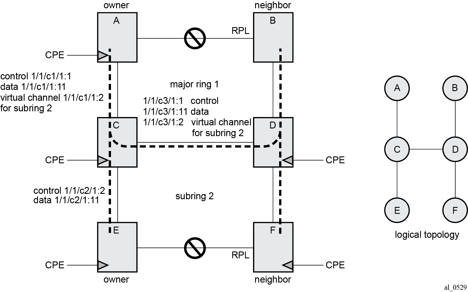
A major ring is a fully connected ring. A subring is a partial ring that depends on a major ring or a VPLS topology for part of the ring interconnect. Two major rings can be connected by a single subring. A subring can support other subrings.
In the major ring (on nodes A, B, C, and D), one path of the RPL owner is designated to be the RPL and the respective SAPs will be blocked in order to prevent a loop. The choice of where to put the RPL is up to the network administrator and can be different for different control instances of the ring allowing an RPL to be used for some other ring's traffic. In the subring, one path is designated as the RPL and will be blocked. Both the major ring and the subring have their own RPL. The subring interconnects to the major ring on nodes C and D and has a virtual channel on the major ring. SR OS supports both virtual channel and non-virtual channel rings. Schematics of the physical and logical topologies are also shown in G.8032 major ring and subring.
The G.8032 protocol defines a ring ID (1-255). The SR OS implementation only uses ring ID 1, which complies with G.8032v2. The configuration on a node uses a ring instance with a number but all rings use ring ID 1. This ring instance number is purely local and does not have to match on other ring nodes. Only the VLAN ID must match between SR OS ring nodes. For consistency in this example, VPLS instances and Ethernet ring instances are shown as matching for the same ring.
An RPL owner and RPL neighbor are configured for both the major ring and subring. The path and associated link will be the RPL when the ring is fully operational and will be blocked by the RPL owner whenever there is no fault on other ring links. Each ring RPL is independent. If a different ring link fails, then the RPL will be unblocked by the RPL owner. The link shared between a subring and the major ring is completely controlled by the major ring as if the subring were not there. Each ring can completely protect one fault within its ring. When the failed link recovers, it will initially be blocked by one of its adjacent nodes. The adjacent node sends an R-APS message across the ring to indicate the error is cleared and after a configurable time, if reversion is enabled, the RPL will revert to being blocked with all other links unblocked. This ensures that the ring topology when fully operational is predictable.
If a specific RPL owner is not configured (not recommended by G.8032 specification), then the last link to become active will be blocked and the ring will remain in this state until another link fails. This operation makes the selection of the blocked link non-deterministic.
The protection protocol uses a specific control VLAN, with the associated data VLANs taking their forwarding state from the control VLAN. The control VLAN cannot carry data.
Load balancing with multiple ring instances
Each control ring is independent of the other control rings on the same topology. Therefore, because the RPL is used by one control ring, it is often desirable to set up a second control ring that uses a different link as RPL. This spreads out traffic in the topology, but if there is a link failure in the ring, all traffic will be on the remaining links. In the following examples, only a single control ring instance is configured. Other control and data rings could be configured if desired.
Provider backbone bridging (PBB)
PBB services also support G.8032 as data services (the services used for the control VPLS must be a regular VPLS). B/I-VPLS rings support both major rings and subrings. B-VPLS rings support multi-chassis link aggregation group (MC-LAG) as a dual homing option when aggregating I-VPLS traffic onto a B-VPLS ring. In other words, I-VPLS rings should not be dual-homed into two backbone edge bridge (BEB) nodes where the B-VPLS uses G.8032 to get connected to the rest of the B-VPLS network because the only mechanism that can propagate MAC flushes between an I-VPLS and B-VPLS is an LDP MAC flush.
SR OS implementation
G.8032 is built from VPLS components and each ring consists of the configuration components illustrated in G.8032 ring components .
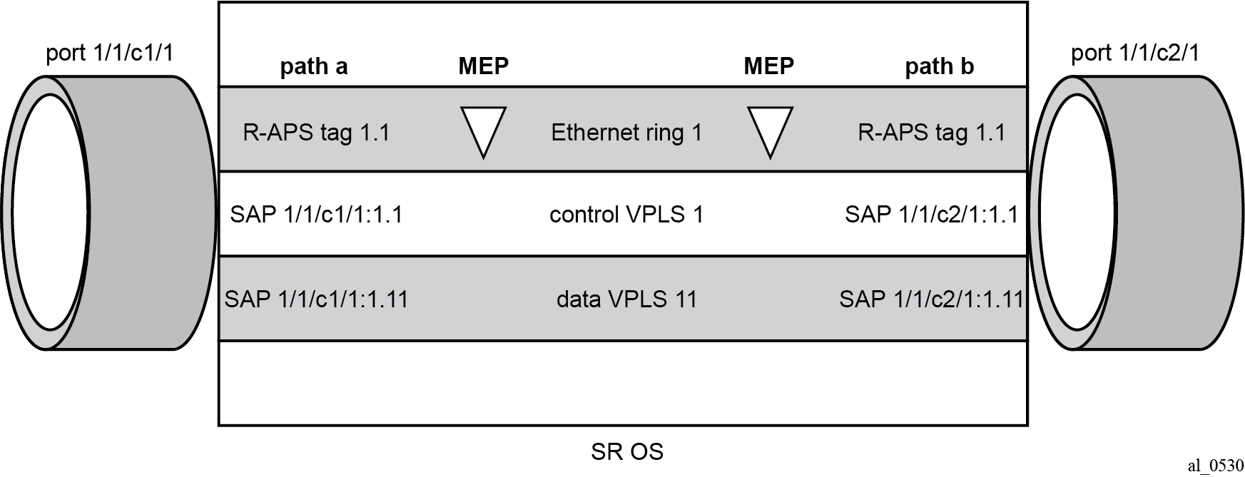
These components consist of:
the Ethernet ring instance which defines the R-APS tags, the MEPs, and the ring behavior.
the control VPLS which has SAPs with an encapsulation that matches the R-APS tags.
the data VPLS which is linked to the ring. All of the data VPLS SAPs follow the operational state of the control VPLS SAPs in that each blocked SAP controlled by the ring is blocked for all control and data instances.
G.8032 subring interconnection components shows the major ring and subring interconnection components:
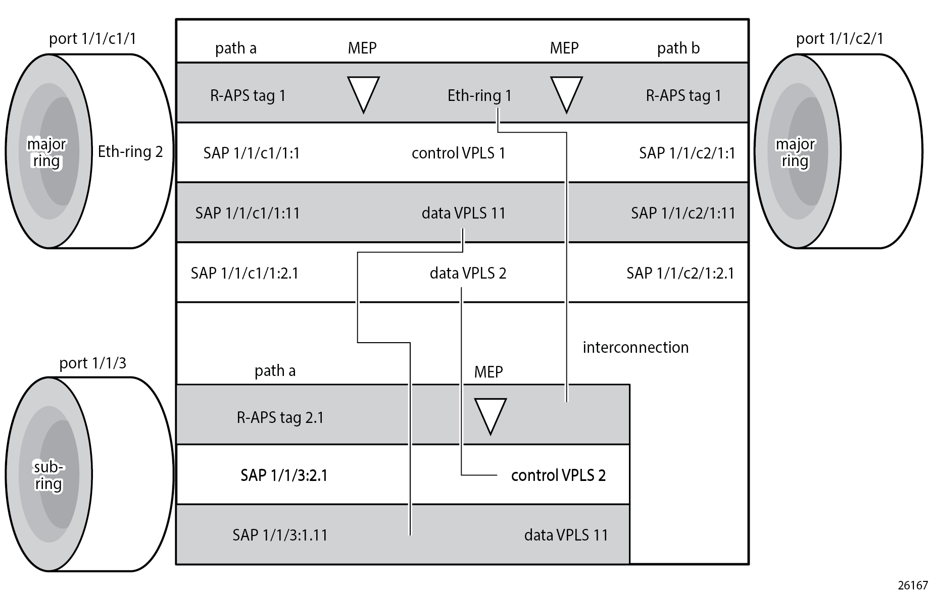
For a subring, the configuration is the same as a single ring except at the junction of the major ring and the subring. The interconnection of a subring and a major ring links the control VPLS of the subring to a data VPLS of the major ring when a virtual link is used. Similarly, the data VPLS of the subring is linked to a data VPLS of the major ring. G.8032 subring interconnection components illustrates the relationship of a subring and a major ring. Because this subring has a virtual channel, the data VPLS 2 has both data SAPs from the subring and data SAPs from the major ring. The virtual channel is also optional and in non-virtual-link cases, no VPLS instance is required (see non-virtual-link in the section Configuration of a subring to a VPLS service).
In G.8032 subring interconnection components, the inner tag values are kept the same for clarity, but in fact any encapsulation that is consistent with the next ring link will work. In other words, ring SAPs can perform VLAN ID translation and even when connecting a subring to a major ring. This also means that other ports may reuse the same tags when connecting independent services.
The R-APS tags and SAPs on the rings can either be dot1Q or QinQ encapsulated. It is also possible to have the control VPLS using single tagged frames with the data VPLSs using double tagged frames; this requires the system to be configured with the extended-default-qinq-sap-lookup parameter (configure service system extended-default-qinq-sap-lookup true), with the ring path R-APS tags and control VPLS SAPs configured as qtag.0, and the data VPLSs configured as QinQ SAP: qtag1.qtag2. Spanning tree protocol (STP) cannot be enabled on SAPs connected to Ethernet rings.
R-APS messages received from other nodes are normally blocked on the RPL interface but the subring case with non-virtual channel recommends that R-APS messages be propagated over the RPL. Configuring sub-ring type non-virtual-link on all nodes on the subring is required to ensure propagation of R-APS messages around the subring.
R-APS messages are forwarded out of the egress using forwarding class network control (NC) and should be prioritized accordingly in the SAP egress QoS policy to ensure that congestion does not cause R-APS messages to be dropped which could cause the ring to switch to another path.
Configuration
This section describes the configuration of multiple rings. The Ethernet ring configuration commands are as follows.
configure {
    eth-ring <ring-index [1..128]> {
        ccm-hold-time {
            down <number>   # Hold timer for down event dampening in centiseconds
            up <number>     # Hold timer for recovery reporting in deciseconds
        }
        compatible-version <number>            # [1..2] - Default: 2
        description <string>
        guard-time <number>       # [1..20] in deciseconds - Default: 5
        node-id <mac-address>     # MAC address of the RPL <xx:xx:xx:xx:xx:xx>
        path <string>             # path ID: string of 1 character
            admin-state <keyword>   # default: disable
            description <string>
            port-and-raps-tag <port-and-encap>     # Port ID and ring APS tag ID
            eth-cfm {
                mep md-admin-name <reference> ma-admin-name <reference> mep-id <number> {
                    admin-state <keyword>   # default: disable
                    ccm <boolean>           # default: false
                    control-mep <boolean>   # default: false
                }
            }
            rpl-end <boolean>               # default: false
        }
        revert-time <number>      # <0,60..720> in seconds - Default: 300
        rpl-node <keyword>        # owner | neighbor
        sub-ring
            interconnect {
                propagate-topology-change <boolean>     # default: false
                ring-id      # Ring instance of the connection ring for the subring
                vpls         # Connect subring to VPLS ID that contains subring SAP
            }
            type             # Subring type (virtual-link|non-virtual-link)
        }
Parameters:
<ring-index> — The ring index is the number by which the ring is referenced; values: 1 to128.
ccm-hold-time { [down <down-timeout>] [up <up-timeout>] }
down — This command specifies the timer which controls the delay between detecting that ring path is down and reporting it to the G.8032 protection module. If a non-zero value is configured, the system will wait for the time specified in the value parameter before reporting it to the G.8032 protection module. This parameter applies only to ring path CCM. It does not apply to the ring port link state. To dampen ring port link state transitions, use the hold-time parameter from the physical member port. This is useful if the underlying path between two nodes is going across an optical system which implements its own protection.
-
up — This command specifies the timer which controls the delay between detecting that ring path is up and reporting it to the G.8032 protection module. If a non-zero value is configured, the system will wait for the time specified in the value parameter before reporting it to the G.8032 protection module. This parameter applies only to ring path CCM. It does not apply to the member port link state. To dampen member port link state transitions, use the hold-time parameter from the physical member port.
Values:
*[ex:/configure eth-ring 1 ccm-hold-time]
A:admin@PE-1# down ?

 down <number>
 <number> - <1..5000> - centiseconds

    Hold timer for down event dampening

*[ex:/configure eth-ring 1 ccm-hold-time]
A:admin@PE-1# up ?

 up <number>
 <number> - <0..5000> - deciseconds
 Default  - 20

    Hold timer for recovery reporting
- The admin-state command allows to enable or disable the Ethernet ring.
The compatible-version command configures the Ethernet ring compatibility version for the G.8032 state machine and messages. The default is version 2 (ITU G.8032v2) and all SR OS systems use version 2. If there is a need to interwork with third party devices that only support version 1, this can be set to version 1 allowing the reception of version 1 PDUs. Version 2 is encoded as 1 in the R-APS messages. Compatibility allows the reception of version 1 (encoded as 0) R-APS PDUs but, as per the G.8032 specification, higher versions are ignored on reception. For SR OS, messages are always originated with version 2. Therefore, if a third party switch supports version 3 (encoded as 2) or higher, interworking is also supported provided the other switch is compatible with version 2.
The description includes a text string of maximum 80 characters to describe the use of the Ethernet ring.
-
guard-time <time> — The forwarding method, in which R-APS messages are copied and forwarded at every Ethernet ring node, can result in a message corresponding to an old request, that is no longer relevant, being received by Ethernet ring nodes. Reception of an old R-APS message may result in erroneous ring state interpretation by some Ethernet ring nodes. The guard timer is used to prevent Ethernet ring nodes from acting upon outdated R-APS messages and prevents the possibility of forming a closed loop. Messages are not forwarded when the guard-timer is running.
Values:
*[ex:/configure eth-ring 1]
A:admin@PE-1# guard-time ?

 guard-time <number>
 <number> - <1..20> - deciseconds
 Default  - 5
The node-id <xx-xx-xx-xx-xx-xx> allows the node identifier to be explicitly configured. By default, the chassis MAC is used. The node ID is not required in typical configurations.
The path parameter defines the paths around the ring, of which there are two in different directions on the ring: an "a" path and a "b" path, except on the interconnection node where a subring connects to another major ring or subring in which case there is one path (either a or b) configured together with the sub-ring command. The paths are configured on a dot1Q or QinQ encapsulated access or hybrid port or a LAG with the encapsulation used for the R-APS messages on the ring. These can be either single tagged or double tagged.
- The admin-state command allows to enable or disable the path.
- The port-and-raps-tag specifies the port ID and the R-APS tag.
The description includes a text string of maximum 80 characters to describe the use of the path.
The eth-cfm context includes the associated Ethernet CFM parameters.
-
mep md-domain-name <reference> ma-domain-name <reference> mep-id <number> — The MEP defined under the path is used for the G.8032 protocol messages, which are based on IEEE 802.1ag/Y.1731 CFM frames.
-
rpl-end — When configured, this path is expected to be one end of the RPL. This parameter must be configured in conjunction with the rpl-node parameter.
-
The revert-time command configures the revert time for an Ethernet ring. The revert time is the time that the RPL will wait before returning to the blocked state, after a failure condition has been fixed. Values: [0, 60..720] in seconds - Default: 300.
When the rpl-node parameter is configured, a node can be designated as either the owner of the RPL, in which case this node is responsible for the RPL, or the neighbor, in which case the node is expected to be the neighbor to the RPL owner across the RPL. The neighbor parameter is optional and is included to be compliant with the specification. The rpl-node parameter must be configured in conjunction with the rpl-end command. On a subring without virtual channel it is mandatory to configure sub-ring type non-virtual-link on all nodes on the subring to ensure propagation of the R-APS messages around the subring.
The sub-ring command is configured on the interconnection node between the subring and its major ring or subring to indicate that this ring is a subring. A ring configured as a subring can only be configured with a single path.
- The type {virtual-link|non-virtual-link} parameter specifies whether it uses a virtual link through the major ring or subring for the R-APS messages or not.
interconnect [ring-id <ring-index> | vpls] — A subring connects to either another ring or to a VPLS service. If it connects to another ring (either a major ring or another subring), the ring identifier must be specified and the ring to which it connects must be configured with both a path "a" and a path "b", meaning that it is not possible to connect a subring to another subring on an interconnection node. Alternatively, the vpls parameter is used to indicate the subring connects to a VPLS service. Interconnection using a VPLS service requires the subring to be configured with type non-virtual-link.
propagate-topology-change — If a topology change event happens in the subring, it can be optionally propagated with the use of this parameter to either the major ring or subring it is connected to, using R-APS messages, or to the LDP VPLS SDP peers using an LDP "flush-all-from-me" message if the subring is connected to a VPLS service.
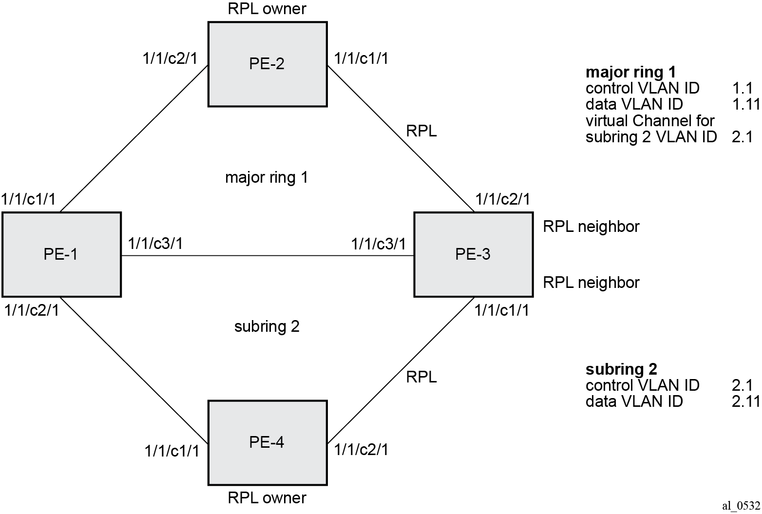
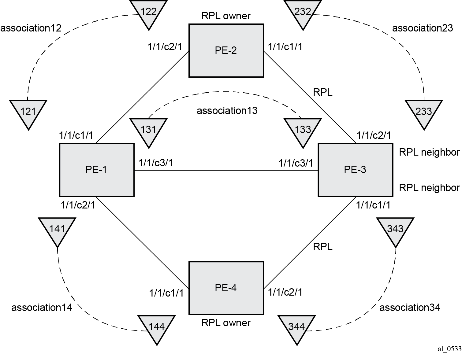
The example topology is shown in Ethernet example topology.
The configuration is divided into the following sections:
a subring connected to a major ring using a virtual link through the major ring
a subring connected to a major ring without a virtual link
a subring connected to a VPLS service (without a virtual link)
Configure a subring to a major ring with a virtual link
To configure an Ethernet ring using R-APS, there will be at least two VPLS services required for one Ethernet ring instance, one for the control channel and the others for data channels. The control channel is used for R-APS signaling while the data channel is for user data traffic. The state of the data channels is inherited from the state of the control channel.
The following needs to be configured:
encapsulation type for each ring port
Ethernet CFM
Ethernet ring for major ring 1
Ethernet ring for subring 2
control channel service and Ethernet ring SAPs
user data channel services
Configure the encapsulation for the ring ports.
An Ethernet ring needs an R-APS tag to send and receive G.8032 signaling messages. To configure a control channel, an access SAP configuration is required on each path (a or b) port. The SAP configuration follows that of the port and must be either dot1Q or QinQ, consequently the control and data packets are either single tagged or double tagged.
Single tagged control frames are supported on a QinQ port by configuring the system with the extended-default-qinq-sap-lookup parameter (configure service system extended-default-qinq-sap-lookup true), and the ring path R -APS tags and control VPLS SAPs configured as qtag.0.
In this example, QinQ tags are used. For example, the port configuration on PE-1 is as follows:
# on PE-1:
configure {
    port 1/1/c1/1 {
        admin-state enable
        ethernet {
            mode access
            encap-type qinq
        }
    }
    port 1/1/c2/1 {
        admin-state enable
        ethernet {
            mode access
            encap-type qinq
        }
    }
    port 1/1/c3/1 {
        admin-state enable
        ethernet {
            mode access
            encap-type qinq
        }
    }
Configure Ethernet CFM
Configuring the Ethernet CFM domain, association, and MEP is required before configuring an Ethernet ring. The standard domain format is none and the association name must be ITU carrier code-based (ICC-based - Y.1731); however, the SR OS implementation is flexible in that it supports both IEEE and ICC formats. The Ethernet ring MEP requires a CCM interval with values such as 1s, 100ms, or 10ms to be configured.
The MEPs used for R-APS control normally will have CCM configured on the control channel path MEPs for failure detection. Alternatively, detecting a failure of the ring may be achieved by running Ethernet in the first mile (EFM) at the port level if CCM is not possible at 1s, 100ms, or 10ms. Also rings can be run without CFM although the Ethernet CFM association must be configured for R-APS messages to be exchanged. To omit the failure detecting CCMs, it is necessary to remove the ccm true from under the path MEPs and to remove the remote-mep on the corresponding ETH CFM configuration.
Loss-of-signal, in conjunction with other OAM mechanisms, is applicable only when the nodes are directly connected.
ETH-CFM MEP associations shows the details of the MEPs and their associations configured when both the major rings and subrings are used. The associations only need to be pairwise unique but for clarity five unique associations are used. Any name format can be used, but it must be consistent on both adjacent nodes.
The configuration of Ethernet CFM for the major and subrings on each node is as follows. The CCMs for failure detection are configured for 1 second intervals.
On ring node PE-1, the associations "association-12" and "association-13" are used for the major ring and association "association-14" is used for the subring.
# on PE-1:
configure {
    eth-cfm {
        domain "domain-1" {
            level 2
            format none
            md-index 1
            association "association-12" {
                icc-based "Association12"
                ma-index 12
                ccm-interval 1s
                remote-mep 122 {
                }
            }
            association "association-13" {
                icc-based "Association13"
                ma-index 13
                ccm-interval 1s
                remote-mep 133 {
                }
            }
            association "association-14" {
                icc-based "Association14"
                ma-index 14
                ccm-interval 1s
                remote-mep 144 {
                }
            }
        }
On ring node PE-2, the associations "association-12" and "association-23" are used for the major ring.
# on PE-2:
configure {
    eth-cfm {
        domain "domain-1" {
            level 2
            format none
            md-index 1
            association "association-12" {
                icc-based "Association12"
                ma-index 12
                ccm-interval 1s
                remote-mep 121 {
                }
            }
            association "association-23" {
                icc-based "Association23"
                ma-index 23
                ccm-interval 1s
                remote-mep 233 {
                }
            }
        }
On ring node PE-3, the associations "association-13" and "association-23" are used for the major ring and association "association-34" is used for the subring.
# on PE-3:
configure {
    eth-cfm {
        domain "domain-1" {
            level 2
            format none
            md-index 1
            association "association-13" {
                icc-based "Association13"
                ma-index 13
                ccm-interval 1s
                remote-mep 131 {
                }
            }
            association "association-23" {
                icc-based "Association23"
                ma-index 23
                ccm-interval 1s
                remote-mep 232 {
                }
            }
            association "association-34" {
                icc-based "Association34"
                ma-index 34
                ccm-interval 1s
                remote-mep 344 {
                }
            }
        }
On ring node PE-4, the associations 14 and 34 are used for the subring.
# on PE-4
configure {
    eth-cfm {
        domain "domain-1" {
            level 2
            format none
            md-index 1
            association "association-14" {
                icc-based "Association14"
                ma-index 14
                ccm-interval 1s
                remote-mep 141 {
                }
            }
            association "association-34" {
                icc-based "Association34"
                ma-index 34
                ccm-interval 1s
                remote-mep 343 {
                }
            }
        }
Configuring Ethernet ring – major ring 1
Two paths must be configured to form a ring. In this example, VLAN tag 1.1 is used as control channel for R-APS signaling for the major ring (Ethernet ring 1) on the ports shown in Ethernet example topology using the Ethernet CFM information shown in ETH-CFM MEP associations. The revert time is set to the value of 60 seconds and CCM messages are enabled on the MEP. The control-mep true command indicates that this MEP is used for ring R-APS messages.
The configuration of Ethernet ring 1 on ring node PE-1 is as follows:
# on PE-1:
configure {
    eth-ring 1 {
        admin-state enable
        description "Ethernet ring 1_major ring"
        revert-time 60
        path "a" {
            admin-state enable
            description "Ethernet ring 1_path a"
            port-and-raps-tag 1/1/c1/1:1.1
            eth-cfm {
                mep md-admin-name "domain-1" ma-admin-name "association-12" mep-id 121 {
                    admin-state enable
                    ccm true
                    control-mep true
                }
            }
        }
        path "b" {
            admin-state enable
            description "Ethernet ring 1_path b"
            port-and-raps-tag 1/1/c3/1:1.1
            eth-cfm {
                mep md-admin-name "domain-1" ma-admin-name "association-13" mep-id 131 {
                    admin-state enable
                    ccm true
                    control-mep true
                }
            }
        }
It is mandatory to configure a MEP in the path context, otherwise the following error is displayed:
*[ex:/configure eth-ring 1 path "a"]
A:admin@PE-1# commit
MINOR: MGMT_CORE #4001: configure eth-ring 1 path "a" admin-state - Cannot enable path
without eth-cfm mep configured - configure eth-ring 1 path "a" admin-state
While MEPs are mandatory, enabling CCMs on the MEPs under the paths as a failure detection mechanism is optional as explained earlier.
Ring node PE-2 is configured as the RPL owner with the RPL being on path "a" as indicated by the rpl-end parameter. The revert time is 60 seconds.
# on PE-2:
configure {
    eth-ring 1 {
        admin-state enable
        description "Ethernet ring 1_major ring"
        revert-time 60
        rpl-node owner
        path "a" {
            admin-state enable
            description "Ethernet ring 1_path a"
            port-and-raps-tag 1/1/c1/1:1.1
            rpl-end true
            eth-cfm {
                mep md-admin-name "domain-1" ma-admin-name "association-23" mep-id 232 {
                    admin-state enable
                    ccm true
                    control-mep true
                }
            }
        }
        path "b" {
            admin-state enable
            description "Ethernet ring 1_path b"
            port-and-raps-tag 1/1/c2/1:1.1
            eth-cfm {
                mep md-admin-name "domain-1" ma-admin-name "association-12" mep-id 122 {
                    admin-state enable
                    ccm true
                    control-mep true
                }
            }
        }
It is not permitted to configure a path as an RPL end without having configured the node on this ring to be either the RPL owner or RPL neighbor, otherwise the following error message is reported.
*[ex:/configure eth-ring 1 path "a"]
A:admin@PE-2# commit
MINOR: MGMT_CORE #4001: configure eth-ring 1 path "a" rpl-end - rpl-node must be set - configure eth-ring 1 rpl-node
Ring node PE-3 is configured as the RPL neighbor with the RPL being on path "b" as indicated by the rpl-end parameter. The revert time is 60 seconds.
# on PE-3:
configure {
    eth-ring 1 {
        admin-state enable
        description "Ethernet ring 1_major ring"
        revert-time 60
        rpl-node neighbor
        path "a" {
            admin-state enable
            description "Ethernet ring 1_path a"
            port-and-raps-tag 1/1/c3/1:1.1
            eth-cfm {
                mep md-admin-name "domain-1" ma-admin-name "association-13" mep-id 133 {
                    admin-state enable
                    ccm true
                    control-mep true
                }
            }
        }
        path "b" {
            admin-state enable
            description "Ethernet ring 1_path b"
            port-and-raps-tag 1/1/c2/1:1.1
            rpl-end true
            eth-cfm {
                mep md-admin-name "domain-1" ma-admin-name "association-23" mep-id 233 {
                    admin-state enable
                    ccm true
                    control-mep true
                }
            }
        }
The link between PE-2 and PE-3 will be the RPL with PE-2 and PE-3 blocking that link when the ring is fully operational. In this example, the RPL is using path "a" on PE-2 and path "b" on PE-3.
Configuring Ethernet ring – subring 2
Ring nodes PE-1, PE-3, and PE-4 form a subring. The subring attaches to the major ring (Ethernet ring 1). The subring in this case uses a virtual link. The interconnection ring instance identifier (ring-id 1) is specified and propagate-topology-change true indicates that subring flushing will be propagated to the major ring. Only one path (path a) is specified because the other path (path b) is not required at an interconnection node. Subrings are almost identical to major rings in operation except that subrings send MAC flushes towards their connected ring (either a major ring or a subring). Major rings or subrings never send MAC flushes to their subrings. Therefore a couple of subrings connected to a major ring can cause MACs to flush on the major ring but the major ring will not propagate a subring MAC flush to other subrings.
Ring node PE-1 provides an interconnection between the major ring (ring 1) and the subring (ring 2). Ring 2 is configured to be a subring which interconnects to ring 1. It will use a virtual link on ring 1 to send R-APS messages to the other interconnection node and topology changes will be propagated from subring 2 to the major ring 1.
# on PE-1:
configure {
    eth-ring 2 {
        admin-state enable
        description "Ethernet subring 2 on major ring 1"
        revert-time 60
        sub-ring {
            type virtual-link
            interconnect {
                ring-id 1
                propagate-topology-change true
            }
        }
        path "a" {
            admin-state enable
            description "Ethernet subring 2_path a"
            port-and-raps-tag 1/1/c2/1:2.1
            eth-cfm {
                mep md-admin-name "domain-1" ma-admin-name "association-14" mep-id 141 {
                    admin-state enable
                    ccm true
                    control-mep true
                }
            }
        }
Subring 2 is not configured on PE-2.
The configuration of subring 2 on PE-3 is similar to PE-1, but PE-3 is the RPL neighbor, with the RPL end on path "a", for the RPL between PE-3 and PE-4.
# on PE-3:
configure {
    eth-ring 2
        admin-state enable
        description "Ethernet subring 2 on major ring 1"
        revert-time 60
        rpl-node neighbor
        sub-ring {
            type virtual-link
            interconnect {
                ring-id 1
                propagate-topology-change true
            }
        }
        path "a" {
            admin-state enable
            description "Ethernet subring 2_path a"
            port-and-raps-tag 1/1/c1/1:2.1
            rpl-end true
            eth-cfm {
                mep md-admin-name "domain-1" ma-admin-name "association-34" mep-id 343 {
                    admin-state enable
                    ccm true
                    control-mep true
                }
            }
        }
Ring node PE-4 only has configuration for the subring 2, not for major ring 1. PE-4 is the RPL owner, with path "b" being the RPL end, for the RPL between PE-3 and PE-4.
# on PE-4:
configure {
    eth-ring 2
        admin-state enable
        description "Ethernet subring 2"
        revert-time 60
        rpl-node owner
        path "a" {
            admin-state enable
            description "Ethernet subring 2_path a"
            port-and-raps-tag 1/1/c1/1:2.1
            eth-cfm {
                mep md-admin-name "domain-1" ma-admin-name "association-14" mep-id 144 {
                    admin-state enable
                    ccm true
                    control-mep true
                }
            }
        }
        path "b" {
            admin-state enable
            description "Ethernet subring 2_path b"
            port-and-raps-tag 1/1/c2/1:2.1
            rpl-end true
            eth-cfm {
                mep md-admin-name "domain-1" ma-admin-name "association-34" mep-id 344 {
                    admin-state enable
                    ccm true
                    control-mep true
                }
            }
        }
Until the Ethernet ring instance is attached to a VPLS service, the ring operational status is down and the forwarding status of each port is blocked. This prevents the operator from creating a loop by misconfiguration. This state can be seen on ring node PE-1 as follows:
[/]
A:admin@PE-1# show eth-ring 1

===============================================================================
Ethernet Ring 1 Information
===============================================================================
Description        : Ethernet ring 1_major ring
Admin State        : Up                 Oper State       : Down
Node ID            : 02:09:ff:00:00:00
Guard Time         :    5 deciseconds   RPL Node         : rplNone
Max Revert Time    :   60 seconds       Time to Revert   : N/A
CCM Hold Down Time :    0 centiseconds  CCM Hold Up Time :   20 deciseconds
Compatible Version : 2
APS Tx PDU         : Request State: 0xB
                     Sub-Code     : 0x0
                     Status       : 0x20  ( BPR )
                     Node ID      : 02:09:ff:00:00:00
Defect Status      :

Sub-Ring Type      : none

-------------------------------------------------------------------------------
Ethernet Ring Path Summary
-------------------------------------------------------------------------------
Path Port             Raps-Tag     Admin/Oper      Type            Fwd State
-------------------------------------------------------------------------------
  a  1/1/c1/1         1.1             Up/Down      normal          blocked
  b  1/1/c3/1         1.1             Up/Down      normal          blocked
===============================================================================
Configure the control channel VPLS service
Path "a" and "b" configured in the Ethernet ring must be added as SAPs into a VPLS service (standard VPLS) using the eth-ring parameter. The SAP encapsulation values must match the values of the R-APS tag configured for the associated path.
G.8032 uses the same R-APS tag value on all nodes on the ring, as configured in this example. However, the SR OS implementation relaxes this constraint by requiring the tag to match only on adjacent nodes.
In this example VPLS "control-VPLS-1" is configured on PE-1, PE-2, and PE-3 for the control channel for the major ring (ring 1), and VPLS "control-VPLS-2" is used on PE-1, PE-3, and PE-4 for the subring (ring 2).
VPLS "control-VPLS-1" is the control service for the major ring and is defined for PE-1, PE-2, and PE-3, as follows:
# on PE-1:
configure {
    service {
         vpls "control-VPLS-1" {
            admin-state enable
            description "Control channel VID 1.1 for ring 1 - major ring"
            service-id 1
            customer "1"
            sap 1/1/c1/1:1.1 {
                eth-ring 1
            }
            sap 1/1/c3/1:1.1 {
                eth-ring 1
            }
        }
# on PE-2:
configure {
    service {
         vpls "control-VPLS-1" {
            admin-state enable
            description "Control channel VID 1.1 for ring 1 - major ring"
            service-id 1
            customer "1"
            sap 1/1/c1/1:1.1 {
                eth-ring 1
            }
            sap 1/1/c2/1:1.1 {
                eth-ring 1
            }
        }
# on PE-3:
configure {
    service {
         vpls "control-VPLS-1" {
            admin-state enable
            description "Control channel VID 1.1 for ring 1 - major ring"
            service-id 1
            customer "1"
            sap 1/1/c2/1:1.1 {
                eth-ring 1
            }
            sap 1/1/c3/1:1.1 {
                eth-ring 1
            }
        }
SAPs or SDPs can be added to a control channel VPLS on condition the eth-ring parameter is present. Any attempt to add a SAP without the eth-ring parameter to a control channel VPLS results in the following messages being displayed.
*[ex:/configure service vpls "control-VPLS-1" sap 1/1/c4/1:1]
A:admin@PE-1# commit
MINOR: SVCMGR #2590: configure service vpls "control-VPLS-1" sap 1/1/c3/1:1.1 - Invalid
Ethernet ring configuration - Ring control SAP cannot be added to service that contains non-
ring SAPs or SDP bindings - configure service vpls "control-VPLS-1" sap 1/1/c3/1:1.1 eth-ring
MINOR: SVCMGR #2590: configure service vpls "control-VPLS-1" sap 1/1/c3/1:1.1 - Invalid
Ethernet ring configuration - Ethernet Ring Control service should only have controls saps
from same ring - configure service vpls "control-VPLS-1" sap 1/1/c3/1:1.1 eth-ring
MINOR: SVCMGR #2590: configure service vpls "control-VPLS-1" sap 1/1/c1/1:1.1 - Invalid
Ethernet ring configuration - Ring control SAP cannot be added to service that contains non-
ring SAPs or SDP bindings - configure service vpls "control-VPLS-1" sap 1/1/c1/1:1.1 eth-ring
MINOR: SVCMGR #2590: configure service vpls "control-VPLS-1" sap 1/1/c1/1:1.1 - Invalid
Ethernet ring configuration - Ethernet Ring Control service should only have controls saps
from same ring - configure service vpls "control-VPLS-1" sap 1/1/c1/1:1.1 eth-ring
For the subring, the configuration of a split horizon group for the virtual channel on the major ring on the interconnection nodes is recommended. This avoids the looping of control R-APS messages in the case there is a misconfiguration in the major ring.
On ring node PE-1, the control service for the subring "control-VPLS-2" is configured as follows. SAP 1/1/c1/1:2.1 and SAP 1/1/c3/1:2.1 connect to the major ring (ring 1) for the virtual channel, whereas SAP 1/1/c2/1:2.1 connects to the subring (ring 2).
# on PE-1:
configure {
    service {
        vpls "control-VPLS-2" {
            admin-state enable
            description "Control/virtual channel VID 2.1 for ring 2"
            service-id 2
            customer "1"
            split-horizon-group "shg-ring2" {
            }
            sap 1/1/c1/1:2.1 {
                description "ring 2 interconnection using ring 1"
                eth-ring 1
                split-horizon-group "shg-ring2"
            }
            sap 1/1/c2/1:2.1 {
                eth-ring 2
            }
            sap 1/1/c3/1:2.1 {
                description "ring 2 interconnection using ring 1"
                eth-ring 1
                split-horizon-group "shg-ring2"
            }
        }
On ring node PE-2, subring 2 is not present. However, the control service "control-VPLS-2" for the subring must be configured on PE-2, because the virtual channel for subring 2 needs to exist throughout major ring 1.
# on PE-2:
configure {
    service {
        vpls "control-VPLS-2" {
            admin-state enable
            description "virtual channel VID 2.1 for ring 2"
            service-id 2
            customer "1"
            sap 1/1/c1/1:2.1 {
                eth-ring 1
            }
            sap 1/1/c2/1:2.1 {
                eth-ring 1
            }
        }
If multiple virtual channels are used (due to the aggregation of multiple subrings into the same major ring), their configuration could be simplified on non-interconnection nodes on the major ring. To achieve this on a ring node such as PE-2, a default SAP could be used rather than configuring a VPLS per virtual channel. If QinQ SAPs are used then default SAPs 1/1/c1/1:qtag.* and 1/1/c2/1:qtag.* could be used but this requires all control channels for subrings to be using qtag as the outer VLAN ID, or 1/1/c1/1:* and 1/1/c2/1:* if dot1Q SAPs were used. This is because the SAPs match explicit SAP definitions first and the default SAP will handle any other traffic.
The following configuration for control service "control-VPLS-2" for the subring on ring node PE-3 is similar to the configuration of PE-1.
# on PE-3:
configure {
    service {
        vpls "control-VPLS-2" {
            admin-state enable
            description "control/virtual channel VID 2.1 for ring 2"
            service-id 2
            customer "1"
            split-horizon-group "shg-ring2" {
            }
            sap 1/1/c1/1:2.1 {
                eth-ring 2
            }
            sap 1/1/c2/1:2.1 {
                description "ring 2 interconnection using ring 1"
                eth-ring 1
                split-horizon-group "shg-ring2"
            }
            sap 1/1/c3/1:2.1 {
                description "ring 2 interconnection using ring 1"
                eth-ring 1
                split-horizon-group "shg-ring2"
            }
        }
On ring node PE-4, control service "control-VPLS-2" for the subring is configured as follows. Both SAPs are configured on the subring (ring 2).
# on PE-4:
configure {
    service {
        vpls "control-VPLS-2" {
            admin-state enable
            description "control VID 2.1 for subring 2"
            service-id 2
            customer "1"
            sap 1/1/c1/1:2.1 {
                eth-ring 2
            }
            sap 1/1/c2/1:2.1 {
                eth-ring 2
            }
        }
At this point, the Ethernet ring 1 is operationally up and the RPL is blocking successfully RPL end port 1/1/c1/1 on RPL owner PE-2 and RPL end port 1/1/c2/1 on RPL neighbor PE-3.
Show output
An overview of all of the rings can be shown using the following commands, in this case on PE-1.
The following command shows the Ethernet ring status on PE-1.
[/]
A:admin@PE-1# show eth-ring status

===============================================================================
Ethernet Ring (Status information)
===============================================================================
Ring   Admin  Oper       Path Information                 MEP Information
ID     State  State  Path         Tag       State     Ctrl-MEP CC-Intvl Defects
-------------------------------------------------------------------------------
1      Up     Up     a - 1/1/c1/1     1.1   Up        Yes      1         -----
                     b - 1/1/c3/1     1.1   Up        Yes      1         -----
2      Up     Up     a - 1/1/c2/1     2.1   Up        Yes      1         -----
                     b - N/A                 -        -        -         -----
===============================================================================
Ethernet Tunnel MEP Defect Legend:
R = Rdi, M = MacStatus, C = RemoteCCM, E = ErrorCCM, X = XconCCM
It is expected that the state is "up", even on ring paths which are blocked. The "Defects" column refers to the CFM defects of the MEPs. If there is a problem, these will be flagged.
The following command shows the ring and path forwarding states on PE-1.
[/]
A:admin@PE-1# show eth-ring

===============================================================================
Ethernet Rings (summary)
===============================================================================
Ring Int  Admin Oper            Paths Summary                       Path States
ID   ID   State State                                               a     b
-------------------------------------------------------------------------------
1    -    Up    Up    a - 1/1/c1/1     1.1   b - 1/1/c3/1     1.1   U     U
2    1    Up    Up    a - 1/1/c2/1     2.1   b - Not configured     U     -
===============================================================================
Ethernet Ring Summary Legend:   B - Blocked    U - Unblocked
The following command shows specific information for major ring 1 on ring node PE-1:
[/]
A:admin@PE-1# show eth-ring 1

===============================================================================
Ethernet Ring 1 Information
===============================================================================
Description        : Ethernet ring 1_major ring
Admin State        : Up                 Oper State       : Up
Node ID            : 02:09:ff:00:00:00
Guard Time         :    5 deciseconds   RPL Node         : rplNone
Max Revert Time    :   60 seconds       Time to Revert   : N/A
CCM Hold Down Time :    0 centiseconds  CCM Hold Up Time :   20 deciseconds
Compatible Version : 2
APS Tx PDU         : N/A
Defect Status      :

Sub-Ring Type      : none

-------------------------------------------------------------------------------
Ethernet Ring Path Summary
-------------------------------------------------------------------------------
Path Port             Raps-Tag     Admin/Oper      Type            Fwd State
-------------------------------------------------------------------------------
  a  1/1/c1/1         1.1             Up/Up        normal          unblocked
  b  1/1/c3/1         1.1             Up/Up        normal          unblocked
===============================================================================
The status around the major ring can also be checked.
The following command shows specific information for major ring 1 on RPL owner PE-2:
[/]
A:admin@PE-2# show eth-ring 1

===============================================================================
Ethernet Ring 1 Information
===============================================================================
Description        : Ethernet ring 1_major ring
Admin State        : Up                 Oper State       : Up
Node ID            : 02:0b:ff:00:00:00
Guard Time         :    5 deciseconds   RPL Node         : rplOwner
Max Revert Time    :   60 seconds       Time to Revert   : N/A
CCM Hold Down Time :    0 centiseconds  CCM Hold Up Time :   20 deciseconds
Compatible Version : 2
APS Tx PDU         : Request State: 0x0
                     Sub-Code     : 0x0
                     Status       : 0x80  ( RB )
                     Node ID      : 02:0b:ff:00:00:00
Defect Status      :

Sub-Ring Type      : none

-------------------------------------------------------------------------------
Ethernet Ring Path Summary
-------------------------------------------------------------------------------
Path Port             Raps-Tag     Admin/Oper      Type            Fwd State
-------------------------------------------------------------------------------
  a  1/1/c1/1         1.1             Up/Up        rplEnd          blocked
  b  1/1/c2/1         1.1             Up/Up        normal          unblocked
===============================================================================
PE-2 is the RPL owner with port 1/1/c1/1 as an RPL end, which is blocked as expected. The revert time is also shown to be the configured value of 60 seconds. Detailed information is shown relating to the R-APS PDUs being transmitted on this ring because PE-2 is the RPL owner.
When a revert is pending after a link failure has been removed, the "Time to Revert" will show the number of seconds remaining before the revert occurs.
The following command shows specific information for major ring 1 on RPL neighbor PE-3:
[/]
A:admin@PE-3# show eth-ring 1

===============================================================================
Ethernet Ring 1 Information
===============================================================================
Description        : Ethernet ring 1_major ring
Admin State        : Up                 Oper State       : Up
Node ID            : 02:0d:ff:00:00:00
Guard Time         :    5 deciseconds   RPL Node         : rplNeighbor
Max Revert Time    :   60 seconds       Time to Revert   : N/A
CCM Hold Down Time :    0 centiseconds  CCM Hold Up Time :   20 deciseconds
Compatible Version : 2
APS Tx PDU         : N/A
Defect Status      :

Sub-Ring Type      : none

-------------------------------------------------------------------------------
Ethernet Ring Path Summary
-------------------------------------------------------------------------------
Path Port             Raps-Tag     Admin/Oper      Type            Fwd State
-------------------------------------------------------------------------------
  a  1/1/c3/1         1.1             Up/Up        normal          unblocked
  b  1/1/c2/1         1.1             Up/Up        rplEnd          blocked
===============================================================================
PE-3 is the RPL neighbor with port 1/1/c2/1 as an RPL end which is blocked as expected.
The information for the subring can also be shown using a similar command. The following command shows specific information for subring 2 on ring node PE-1:
[/]
A:admin@PE-1# show eth-ring 2

===============================================================================
Ethernet Ring 2 Information
===============================================================================
Description        : Ethernet subring 2 on major ring 1
Admin State        : Up                 Oper State       : Up
Node ID            : 02:09:ff:00:00:00
Guard Time         :    5 deciseconds   RPL Node         : rplNone
Max Revert Time    :   60 seconds       Time to Revert   : N/A
CCM Hold Down Time :    0 centiseconds  CCM Hold Up Time :   20 deciseconds
Compatible Version : 2
APS Tx PDU         : N/A
Defect Status      :

Sub-Ring Type      : virtualLink        Interconnect-ID  : 1
Topology Change    : Propagate

-------------------------------------------------------------------------------
Ethernet Ring Path Summary
-------------------------------------------------------------------------------
Path Port             Raps-Tag     Admin/Oper      Type            Fwd State
-------------------------------------------------------------------------------
  a  1/1/c2/1         2.1             Up/Up        normal          unblocked
  b  -                -                 -/-         -               -
===============================================================================
Only path "a" is active and unblocked. Path "b" is not configured because only one path is required on an interconnection node. The "Sub-Ring Type" is shown to be a virtual link interconnecting to ring 1, with topology propagation enabled.
The following command shows specific information for subring 2 on ring node PE-3:
[/]
A:admin@PE-3# show eth-ring 2

===============================================================================
Ethernet Ring 2 Information
===============================================================================
Description        : Ethernet subring 2 on major ring 1
Admin State        : Up                 Oper State       : Up
Node ID            : 02:0d:ff:00:00:00
Guard Time         :    5 deciseconds   RPL Node         : rplNeighbor
Max Revert Time    :   60 seconds       Time to Revert   : N/A
CCM Hold Down Time :    0 centiseconds  CCM Hold Up Time :   20 deciseconds
Compatible Version : 2
APS Tx PDU         : N/A
Defect Status      :

Sub-Ring Type      : virtualLink        Interconnect-ID  : 1
Topology Change    : Propagate

-------------------------------------------------------------------------------
Ethernet Ring Path Summary
-------------------------------------------------------------------------------
Path Port             Raps-Tag     Admin/Oper      Type            Fwd State
-------------------------------------------------------------------------------
  a  1/1/c1/1         2.1             Up/Up        rplEnd          blocked
  b  -                -                 -/-         -               -
===============================================================================
PE-3 is the RPL neighbor with port 1/1/c1/1 as an RPL end, which is blocked as expected.
The following command shows specific information for subring 2 on ring node PE-4:
[/]
A:admin@PE-4# show eth-ring 2

===============================================================================
Ethernet Ring 2 Information
===============================================================================
Description        : Ethernet subring 2
Admin State        : Up                 Oper State       : Up
Node ID            : 02:0f:ff:00:00:00
Guard Time         :    5 deciseconds   RPL Node         : rplOwner
Max Revert Time    :   60 seconds       Time to Revert   : N/A
CCM Hold Down Time :    0 centiseconds  CCM Hold Up Time :   20 deciseconds
Compatible Version : 2
APS Tx PDU         : Request State: 0x0
                     Sub-Code     : 0x0
                     Status       : 0xE0  ( RB DNF BPR )
                     Node ID      : 02:0f:ff:00:00:00
Defect Status      :

Sub-Ring Type      : none

-------------------------------------------------------------------------------
Ethernet Ring Path Summary
-------------------------------------------------------------------------------
Path Port             Raps-Tag     Admin/Oper      Type            Fwd State
-------------------------------------------------------------------------------
  a  1/1/c1/1         2.1             Up/Up        normal          unblocked
  b  1/1/c2/1         2.1             Up/Up        rplEnd          blocked
===============================================================================
PE-4 is the RPL owner with port 1/1/c2/1 as an RPL end, which is blocked as expected.
The following command shows the details of an individual path.
[/]
A:admin@PE-1# show eth-ring 1 path a

===============================================================================
Ethernet Ring 1 Path Information
===============================================================================
Description        : Ethernet ring 1_path a
Port               : 1/1/c1/1           Raps-Tag         : 1.1
Admin State        : Up                 Oper State       : Up
Path Type          : normal             Fwd State        : unblocked
                                        Fwd State Change : 05/16/2023 08:14:44
Last Switch Command: noCmd
APS Rx PDU         : Request State: 0x0
                     Sub-Code     : 0x0
                     Status       : 0x80  ( RB )
                     Node ID      : 02:0b:ff:00:00:00

===============================================================================
The ring hierarchy created can be shown, either for all rings, or as follows for a specific ring.
[/]
A:admin@PE-1# show eth-ring 1 hierarchy

===============================================================================
Ethernet Ring 1 (hierarchy)
===============================================================================
Ring Int  Admin Oper            Paths Summary                       Path States
ID   ID   State State                                               a     b
-------------------------------------------------------------------------------
1    -    Up    Up    a - 1/1/c1/1     1.1   b - 1/1/c3/1     1.1   U     U
2    1    Up    Up    a - 1/1/c2/1     2.1   b - Not configured     U     -
===============================================================================
Ethernet Ring Summary Legend:   B - Blocked    U - Unblocked
Configure the user data channel VPLS service
The user data channels are created on a separate VPLS, "VPLS-11" in this example, using VLAN tag 1.11. The ring data channels must be on the same ports as the corresponding control channels configured above. The access into the data services can use normal SAPs or SDPs, for example the SAP on port 1/1/c4/1 in the following output. Customer data traverses the ring on a data SAP. Multiple parallel data SAPs in different data services can be controlled by one control ring instance, Ethernet ring 1 in the example.
Data VPLS "VPLS-11" on ring node PE-1 has data SAPs 1/1/c1/1:1.11 and 1/1/c3/1:1.11 on major ring 1, while SAP 1/1/c2/1:1.11 is the data SAP on subring 2.
# on PE-1:
configure {
    service {
        vpls "VPLS-11" {
            admin-state enable
            description "data VPLS"
            service-id 11
            customer "1"
            sap 1/1/c1/1:1.11 {
                eth-ring 1
            }
            sap 1/1/c2/1:1.11 {
                eth-ring 2
            }
            sap 1/1/c3/1:1.11 {
                eth-ring 1
            }
            sap 1/1/c4/1:11 {
                description "sample customer service SAP"
            }
        }
The configuration of data VPLS "VPLS-11" on ring node PE-3 (not shown) is similar to ring node PE-1.
The configuration of data VPLS "VPLS-11" on ring node PE-2 has data SAPs 1/1/c1/1:1.11 and 1/1/c3/1:1.11 on major ring 1.
# on PE-2:
configure {
    service {
        vpls "VPLS-11" {
            admin-state enable
            description "data VPLS"
            service-id 11
            customer "1"
            sap 1/1/c1/1:1.11 {
                eth-ring 1
            }
            sap 1/1/c2/1:1.11 {
                eth-ring 1
            }
            sap 1/1/c4/1:11 {
                description "sample customer service SAP"
            }
        }
The configuration of data VPLS "VPLS-11" on ring node PE-4 has data SAPs 1/1/c1/1:1.11 and 1/1/c3/1:1.11 on subring 2.
# on PE-4:
configure {
    service {
        vpls "VPLS-11" {
            admin-state enable
            description "data VPLS"
            service-id 11
            customer "1"
            sap 1/1/c1/1:1.11 {
                eth-ring 2
            }
            sap 1/1/c2/1:1.11 {
                eth-ring 2
            }
            sap 1/1/c4/1:11 {
                description "sample customer service SAP"
            }
        }
All the SAPs which are configured to use Ethernet rings can be displayed. The following output is taken from PE-1, where there are:
two SAPs in VPLS 1 for the control channel of ring 1 (VLAN ID 1.1)
two SAPs in VPLS 2 on ring 1 for the virtual channel for ring 2 (VLAN ID 2.1)
one SAP in VPLS 2 on ring 2 for the control channel for ring 2 (VLAN ID 2.1)
three SAPs in VPLS 11, two on ring 1 and one on ring 2, for the data service (VLAN ID 1.11). This matches the information in G.8032 subring interconnection components.
[/]
A:admin@PE-1# show service sap-using eth-ring

===============================================================================
Service Access Points (Ethernet Ring)
===============================================================================
SapId                    SvcId       Eth-Ring Path Admin Oper  Blocked Control/
                                                   State State         Data
-------------------------------------------------------------------------------
1/1/c1/1:1.1             1           1        a    Up    Up    No      Ctrl
1/1/c3/1:1.1             1           1        b    Up    Up    No      Ctrl
1/1/c1/1:2.1             2           1        a    Up    Up    No      Ctrl
1/1/c2/1:2.1             2           2        a    Up    Up    No      Ctrl
1/1/c3/1:2.1             2           1        b    Up    Up    No      Ctrl
1/1/c1/1:1.11            11          1        a    Up    Up    No      Data
1/1/c2/1:1.11            11          2        a    Up    Up    No      Data
1/1/c3/1:1.11            11          1        b    Up    Up    No      Data
-------------------------------------------------------------------------------
Number of SAPs : 8
===============================================================================
Statistics are available showing both the CCM and R-APS messages sent and received on a node. An associated clear command is available.
[/]
A:admin@PE-1# show eth-cfm statistics

===============================================================================
ETH-CFM System Statistics
===============================================================================
Rx Count           : 5973               Tx Count           : 6820
Dropped Congestion : 0                  Discarded Error    : 0
AIS Currently Act  : 0                  AIS Currently Fail : 0
===============================================================================

=================================
ETH-CFM System Op-code Statistics
=================================
Op-code      Rx Count   Tx Count
---------------------------------
ccm              4936       6002
lbr                 0          0
lbm                 0          0
ltr                 0          0
ltm                 0          0
ais                 0          0
lck                 0          0
tst                 0          0
laps                0          0
raps             1037        818
mcc                 0          0
lmr                 0          0
lmm                 0          0
1dm                 0          0
dmr                 0          0
dmm                 0          0
exr                 0          0
exm                 0          0
csf                 0          0
vsr                 0          0
vsm                 0          0
1sl                 0          0
slr                 0          0
slm                 0          0
gnm                 0          0
other               0          0
---------------------------------
Total            5973       6820
=================================
To see an example of the messages in log "99" on a ring failure, when the unblocked port 1/1/c2/1 on PE-2 is disabled, the following messages are displayed. When logging is enabled from main to console, the same messages can be seen on the console.
# on PE-2:
configure {
    port 1/1/c2/1
        admin-state disable
74 2023/05/16 08:43:40.190 CEST MINOR: ETH_CFM #2001 Base
"MEP 1/12/122 highest defect is now defRemoteCCM"

73 2023/05/16 08:43:36.641 CEST MAJOR: SVCMGR #2210 Base
"Processing of an access port state change event is finished and the status of all
affected SAPs on port 1/1/c2/1 has been updated."

72 2023/05/16 08:43:36.640 CEST MINOR: ERING #2001 Base eth-ring-1
"Eth-Ring 1 path a changed fwd state to unblocked"

71 2023/05/16 08:43:36.640 CEST MINOR: ERING #2001 Base eth-ring-1
"Eth-Ring 1 path b changed fwd state to blocked"

70 2023/05/16 08:43:36.640 CEST WARNING: SNMP #2004 Base 1/1/c2/1
"Interface 1/1/c2/1 is not operational"
For troubleshooting, the tools dump eth-ring <ring-index> command displays path information, the internal state of the control protocol, related statistics information, and up to the last 16 protocol events (including messages sent and received, and the expiration of timers). An associated clear parameter exists, which clears the event information in this output when the command is entered. The following is an example of the output on PE-2 after port 1/1/c2/1 has been enabled.
[/]
A:admin@PE-2# tools dump eth-ring 1

ringId 1 (Up/Up): numPaths 2 nodeId 02:0b:ff:00:00:00
 SubRing: none (interconnect ring 0, propagateTc  No), Cnt 0
  path-a, port 1/1/c1/1 (Up), tag 1.1(Up) status (Up/Up/Blk)
      cc (Dn/Up): Cnt 1/1 tm 000 00:25:53.470/000 00:36:36.970
      state: Cnt 7 B/F 000 01:10:19.470/000 01:05:31.920, flag: 0x0
  path-b, port 1/1/c2/1 (Up), tag 1.1(Up) status (Up/Up/Fwd)
      cc (Dn/Up): Cnt 2/2 tm 000 01:05:35.480/000 01:09:02.180
      state: Cnt 4 B/F 000 01:05:31.920/000 01:10:19.470, flag: 0x0
  FsmState=  IDLE, Rpl = Owner, revert = 60 s, guard = 5 ds
    Defects =
    Running Timers = PduReTx
    lastTxPdu = 0x0080 Nr(RB )
    path-a Rpl, RxId(I)= 02:09:ff:00:00:00, rx(F)= v1-0x0000 Nr, cmd= None
    path-b Normal, RxId(I)= 02:09:ff:00:00:00, rx(F)= v1-0x0000 Nr, cmd= None
  DebugInfo:  aPathSts 3, bPathSts 3, pm (set/clr) 0/0, txFlush 0
    RxRaps: ok 9 nok 0 self 36, TmrExp - wtr 2(1), grd 2, wtb 0
    Flush: cnt 8 (6/1/1) tm 000 01:10:19.470-000 01:10:19.470 Out/Ack 0/1
    RxRawRaps: aPath 85 bPath 45 vPath 0
    Now: 000 01:20:37.210 , softReset: No - noTx 0

  Seq Event  RxInfo(Path: NodeId-Bytes)
             state:TxInfo (Bytes)            Dir  pA  pB        Time
  === ===== ==============================  ===== === === ================
  001  bAdd
              PROT  : 0xb020  Sf            TxF-> Blk Blk 000 00:25:49.470
  002   aUp
              PROT  : 0xb060  Sf(DNF)       Tx--> Fwd Blk 000 00:25:49.470
  003   aDn
              PROT  : 0xb000  Sf            TxF-> Blk Blk 000 00:25:53.470
  004   pdu B: 02:09:ff:00:00:00-0xb040 Sf(DNF)
              PROT  : 0xb000  Sf            Rx<-- Blk Blk 000 00:36:38.180
  005   pdu B: 02:09:ff:00:00:00-0x0000 Nr
              PROT  : 0xb000  Sf            Rx<-- Blk Blk 000 00:36:38.480
  006   pdu A: 02:0d:ff:00:00:00-0x0020 Nr
              PROT  : 0xb000  Sf            Rx<-- Blk Blk 000 00:36:38.960
  007   pdu B: 02:0d:ff:00:00:00-0x0020 Nr
              PROT  : 0xb000  Sf            Rx<-- Blk Blk 000 00:36:39.160
  008   bUp
              PROT  : 0xb040  Sf(DNF)       Tx--> Blk Fwd 000 00:36:39.170
  009   aUp
              PEND-G: 0x0000  Nr            Tx--> Blk Fwd 000 00:36:39.470
  010   pdu B: 02:09:ff:00:00:00-0xe000 Ev
              PEND  : 0x0000  Nr            Frx<- Blk Fwd 000 00:36:40.430
  011   pdu A: 02:0d:ff:00:00:00-0x0020 Nr
              PEND  : 0x0000  Nr            Rx<-- Blk Fwd 000 00:36:40.440
  012   pdu
              PEND  :                       ----- Fwd Fwd 000 00:36:40.440
  013   pdu B: 02:0d:ff:00:00:00-0x0020 Nr
              PEND  :                       Rx<-- Fwd Fwd 000 00:36:40.440
  014  xWtr
              IDLE  : 0x0080  Nr(RB )       TxF-> Blk Fwd 000 00:37:40.470
  015   bDn
              PROT  : 0xb020  Sf            TxF-> Fwd Blk 000 01:05:31.920
  016   pdu A: 02:09:ff:00:00:00-0xb000 Sf
              PROT  : 0xb020  Sf            RxF<- Fwd Blk 000 01:05:35.190
  017   pdu B: 02:09:ff:00:00:00-0x0000 Nr
              PROT  : 0xb020  Sf            Rx<-- Fwd Blk 000 01:09:03.480
  018   pdu A: 02:09:ff:00:00:00-0x0000 Nr
              PROT  : 0xb020  Sf            Rx<-- Fwd Blk 000 01:09:03.490
  019   bUp
              PEND-G: 0x0020  Nr            Tx--> Fwd Blk 000 01:09:04.170
  000  xWtr
              IDLE  : 0x0080  Nr(RB )       TxF-> Blk Fwd 000 01:10:19.470
Configuration of a subring to a major ring with a non-virtual link
The differences from the preceding virtual link configuration with a non-virtual link for the subring are:
The subring configuration on the interconnection nodes, PE-1 and PE-3, is modified to indicate that the subring is not using a virtual link, otherwise it remains the same.
The subring configuration on the subring node PE-4 is also modified to indicate that this is part of a subring that is not using a virtual link. This is mandatory on all non-interconnection nodes on the subring in order to ensure the propagation of R-APS messages around the subring.
The virtual link services and SAPs must be removed from PE-1, PE-2, and PE3, that is:
On PE-1 and PE-3, the SAPs in VPLS 2 around the major ring (configured with the parameter eth-ring 1) are removed.
The service "control-VPLS-2" is removed completely from PE-2.
The new configuration of subring 2 on PE-1 is as follows, the configuration on PE-3 is similar.
# on PE-1:
configure {
    eth-ring 2 {
        admin-state enable
        description "Ethernet subring 2 on major ring 1"
        revert-time 60
        sub-ring {
            type non-virtual-link
            interconnect {
                ring-id 1
                propagate-topology-change true
            }
        }
        path "a" {
            admin-state enable
            description "Ethernet subring 2_path a"
            port-and-raps-tag 1/1/c2/1:2.1
            eth-cfm {
                mep md-admin-name "domain-1" ma-admin-name "association-14" mep-id 141 {
                    admin-state enable
                    ccm true
                    control-mep true
                }
            }
        }
The configuration of subring 2 on non-interconnection node PE-4 must include the type non-virtual-link parameter, as follows:
# on PE-4:
configure {
    eth-ring 2 {
        admin-state enable
        description "Ethernet subring 2"
        revert-time 60
        rpl-node owner
        sub-ring {
            type non-virtual-link
        }
        path "a" {
            admin-state enable
            description "Ethernet subring 2_path a"
            port-and-raps-tag 1/1/c1/1:2.1
            eth-cfm {
                mep md-admin-name "domain-1" ma-admin-name "association-14" mep-id 144 {
                    admin-state enable
                    ccm true
                    control-mep true
                }
            }
        }
        path "b" {
            admin-state enable
            description "Ethernet subring 2_path b"
            port-and-raps-tag 1/1/c2/1:2.1
            rpl-end true
            eth-cfm {
                mep md-admin-name "domain-1" ma-admin-name "association-34" mep-id 344 {
                    admin-state enable
                    ccm true
                    control-mep true
                }
            }
        }
The SAP usage on PE-1 is as follows with only the control and data SAPs to PE-4 now using subring 2.
[/]
A:admin@PE-1# show service sap-using eth-ring

===============================================================================
Service Access Points (Ethernet Ring)
===============================================================================
SapId                    SvcId       Eth-Ring Path Admin Oper  Blocked Control/
                                                   State State         Data
-------------------------------------------------------------------------------
1/1/c1/1:1.1             1           1        a    Up    Up    No      Ctrl
1/1/c3/1:1.1             1           1        b    Up    Up    No      Ctrl
1/1/c2/1:2.1             2           2        a    Up    Up    No      Ctrl
1/1/c1/1:1.11            11          1        a    Up    Up    No      Data
1/1/c2/1:1.11            11          2        a    Up    Up    No      Data
1/1/c3/1:1.11            11          1        b    Up    Up    No      Data
-------------------------------------------------------------------------------
Number of SAPs : 6
===============================================================================
The information relating to subring 2 is as follows and it can be seen that this is now not using a virtual link, but subring 2 is still connected to major ring 1 and propagation is still enabled from the subring to the major ring. The single ring path "a" is unblocked because the RPL is configured between PE-3 and PE-4.
[/]
A:admin@PE-1# show eth-ring 2

===============================================================================
Ethernet Ring 2 Information
===============================================================================
Description        : Ethernet subring 2 on major ring 1
Admin State        : Up                 Oper State       : Up
Node ID            : 02:09:ff:00:00:00
Guard Time         :    5 deciseconds   RPL Node         : rplNone
Max Revert Time    :   60 seconds       Time to Revert   : N/A
CCM Hold Down Time :    0 centiseconds  CCM Hold Up Time :   20 deciseconds
Compatible Version : 2
APS Tx PDU         : N/A
Defect Status      :

Sub-Ring Type      : nonVirtualLink     Interconnect-ID  : 1
Topology Change    : Propagate

-------------------------------------------------------------------------------
Ethernet Ring Path Summary
-------------------------------------------------------------------------------
Path Port             Raps-Tag     Admin/Oper      Type            Fwd State
-------------------------------------------------------------------------------
  a  1/1/c2/1         2.1             Up/Up        normal          unblocked
  b  -                -                 -/-         -               -
===============================================================================
Configuration of a subring to a VPLS service
Subrings can be connected to VPLS services, in which case a virtual link is not used and is not configurable. While similar to the ring interconnect, there are a few differences.
Flush propagation is from the subring to the VPLS, in the same way as it was for the subring to the major ring. The same configuration parameter is used to propagate topology changes. In this case, LDP "flush-all-from-me" messages are sent into the LDP portion of the network to account for ring changes without the need to configure anything in the VPLS service.
As with other rings, until an Ethernet ring instance is attached to the VPLS service, the ring operational status is down and the forwarding status of each port is blocked. This prevents operators from creating a loop by misconfiguration.
The topology for this case is shown in Subring to VPLS topology. The configuration is very similar to the subring with a non-virtual link described earlier, but ring 1 is replaced by a VPLS service using LDP-signaled mesh SDPs between PE-1, PE-2, and PE-3 to create a fully meshed VPLS service. Both spoke and mesh SDPs using LDP can be used for the VPLS; however, only mesh SDPs have been used in this example.
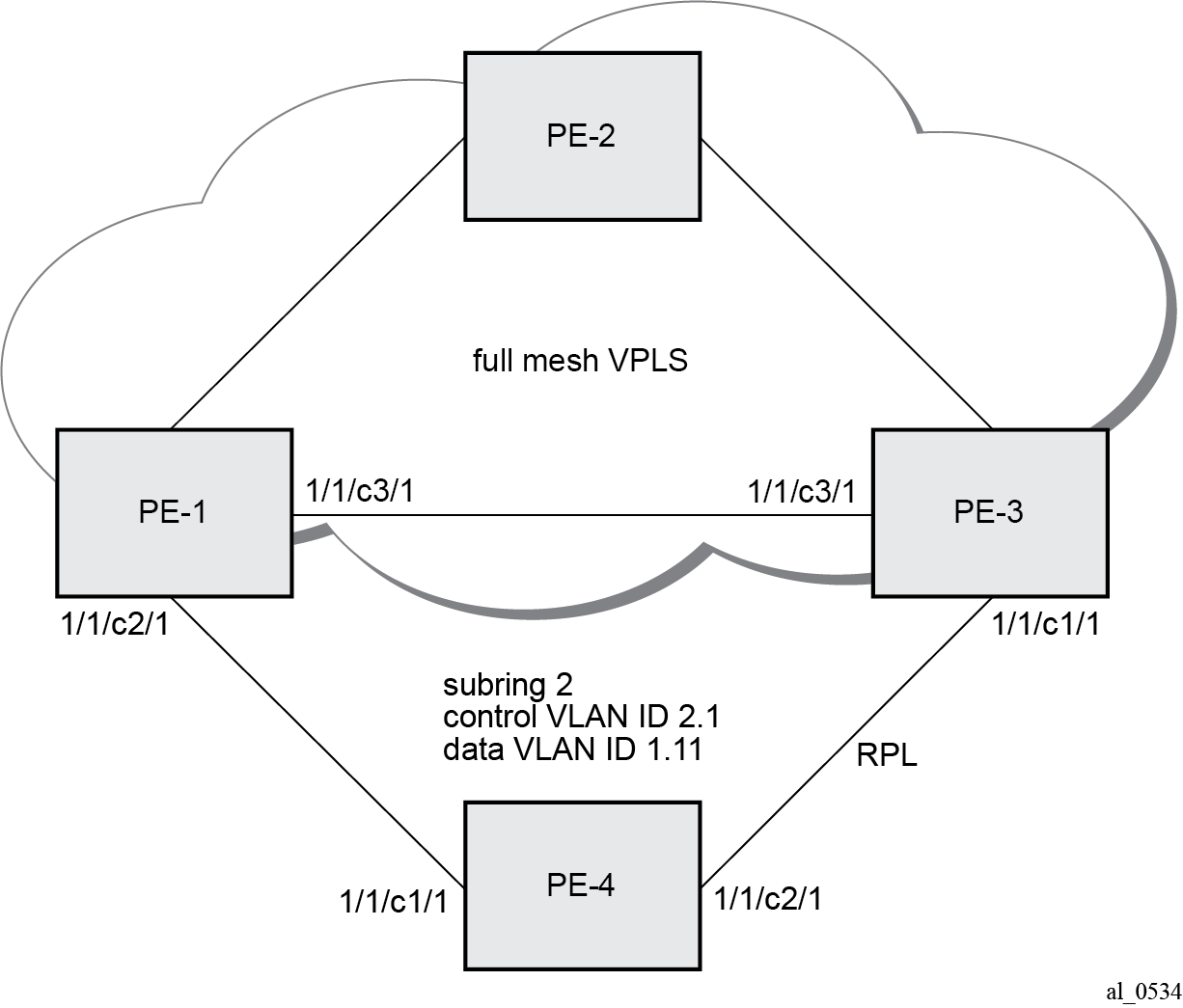
The differences for the VPLS service connection to the configuration when the subring is connected to a major ring without a virtual link are:
The subring configuration on the interconnection nodes, PE-1 and PE-3, is modified to indicate that the subring is connected to a VPLS service.
The subring configuration on the non-interconnection node PE-4 indicates that this is part of a subring that is not using a virtual link (same configuration as in the scenario when a subring is connected to a major ring without a virtual link). This is mandatory on all non-interconnection nodes on the subring in order to ensure the propagation of R-APS messages around the subring.
The control VPLS "control-VPLS-1" and SAPs relating to the major ring 1 on PE-1, PE-2, and PE-3 are removed. These are replaced by routed IP interfaces configured with a routing protocol and LDP in order to signal the required MPLS labels, together with the necessary SDPs to provide interconnection at a service level.
The data service "VPLS-11" is configured with mesh SDPs between PE-1, PE-2, and PE-3.
The configuration on PE-1 of the subring 2 is as follows with the interconnect indicating a VPLS service. The configuration on PE-3 is similar.
# on PE-1:
configure {
    eth-ring 2 {
        admin-state enable
        description "Ethernet subring 2 on VPLS"
        revert-time 60
        sub-ring {
            type non-virtual-link
            interconnect {
                vpls
                propagate-topology-change true
            }
        }
        path "a" {
            admin-state enable
            description "Ethernet subring 2_path a"
            port-and-raps-tag 1/1/c2/1:2.1
            eth-cfm {
                mep md-admin-name "domain-1" ma-admin-name "association-14" mep-id 141 {
                    admin-state enable
                    ccm true
                    control-mep true
                }
            }
        }
The following configuration of subring 2 on non-interconnection node PE-4 includes the type non-virtual-link parameter:
# on PE-4:
configure {
    eth-ring 2 {
        admin-state enable
        description "Ethernet subring 2"
        revert-time 60
        rpl-node owner
        sub-ring {
            type non-virtual-link
        }
        path "a" {
            admin-state enable
            description "Ethernet subring 2_path a"
            port-and-raps-tag 1/1/c1/1:2.1
            eth-cfm {
                mep md-admin-name "domain-1" ma-admin-name "association-14" mep-id 144 {
                    admin-state enable
                    ccm true
                    control-mep true
                }
            }
        }
        path "b" {
            admin-state enable
            description "Ethernet subring 2_path b"
            port-and-raps-tag 1/1/c2/1:2.1
            rpl-end true
            eth-cfm {
                mep md-admin-name "domain-1" ma-admin-name "association-34" mep-id 344 {
                    admin-state enable
                    ccm true
                    control-mep true
                }
            }
        }
The data service on PE-1 is as follows. The configuration on PE-3 is similar.
# on PE-1:
configure {
    service {
        vpls "VPLS-11" {
            admin-state enable
            description "data VPLS"
            service-id 11
            customer "1"
            mesh-sdp 12:11 {
            }
            mesh-sdp 13:11 {
            }
            sap 1/1/c2/1:1.11 {
                eth-ring 2
            }
            sap 1/1/c4/1:11 {
                description "sample customer service SAP"
            }
The state of the subring is as follows and shows the subring is not using a virtual link, is connected to a VPLS service, and has propagation of topology change events enabled. As earlier, the single ring path "a" is unblocked because the RPL is configured between PE-3 and PE-4.
[/]
A:admin@PE-1# show eth-ring 2

===============================================================================
Ethernet Ring 2 Information
===============================================================================
Description        : Ethernet subring 2 on VPLS
Admin State        : Up                 Oper State       : Up
Node ID            : 02:09:ff:00:00:00
Guard Time         :    5 deciseconds   RPL Node         : rplNone
Max Revert Time    :   60 seconds       Time to Revert   : N/A
CCM Hold Down Time :    0 centiseconds  CCM Hold Up Time :   20 deciseconds
Compatible Version : 2
APS Tx PDU         : N/A
Defect Status      :

Sub-Ring Type      : nonVirtualLink     Interconnect-ID  : VPLS
Topology Change    : Propagate

-------------------------------------------------------------------------------
Ethernet Ring Path Summary
-------------------------------------------------------------------------------
Path Port             Raps-Tag     Admin/Oper      Type            Fwd State
-------------------------------------------------------------------------------
  a  1/1/c2/1         2.1             Up/Up        normal          unblocked
  b  -                -                 -/-         -               -
===============================================================================
In this case, if a topology change event occurs in the subring, an LDP "flush-all-from-me" message is sent by PE-1 and PE-3 to their LDP peers. This can be seen by enabling the following debugging for PE-1:
# on PE-1:
debug {
    router "Base" {
        ldp {
            peer 192.0.2.2 {
                packet {
                    init {
                    }
                }
            }
            peer 192.0.2.3 {
                packet {
                    init {
                    }
                }
            }
The topology change is forced by disabling port 1/1/c2/1 on PE-1.
# on PE-1:
configure {
    port 1/1/c2/1
        admin-state disable
The log shows the following messages on the console (combination of log 1 for debug-trace and log 2 for main), where packets 1 and 2 are the LDP flush messages.
88 2023/05/16 09:39:27.293 CEST WARNING: SNMP #2004 Base 1/1/c2/1
"Interface 1/1/c2/1 is not operational"

89 2023/05/16 09:39:27.293 CEST MINOR: ERING #2001 Base eth-ring-2
"Eth-Ring 2 path a changed fwd state to blocked"

1 2023/05/16 09:39:27.294 CEST MINOR: DEBUG #2001 Base LDP
"LDP: LDP
Send Address Withdraw packet (msgId 191) to 192.0.2.2:0
 MAC Flush (All MACs learned from me)
Service FEC PWE3: ENET(5)/11 Group ID = 0 cBit = 0
"

2 2023/05/16 09:39:27.294 CEST MINOR: DEBUG #2001 Base LDP
"LDP: LDP
Send Address Withdraw packet (msgId 190) to 192.0.2.3:0
 MAC Flush (All MACs learned from me)
Service FEC PWE3: ENET(5)/11 Group ID = 0 cBit = 0
"

90 2023/05/16 09:39:27.299 CEST MAJOR: SVCMGR #2210 Base
"Processing of an access port state change event is finished and the status of a
ll affected SAPs on port 1/1/c2/1 has been updated."

91 2023/05/16 09:39:30.909 CEST MINOR: ETH_CFM #2001 Base
"MEP 1/14/141 highest defect is now defRemoteCCM"
Operational procedures
Operators may wish to configure rings with or without control over reversion. Reversion can be controlled by timers or the ring can be run without reversion allowing the operator to choose when the ring reverts. To change a ring topology, the manual or force switch command may be used to block a specified ring path. A ring will still address failures when run without reversion but will not automatically revert to the RPL when resources are restored. A clear command can be used to clear the manual or force state of a ring.
The following tools commands are available to control the state of paths on a ring.
tools perform eth-ring clear <ring-index>
tools perform eth-ring force <ring-index> path {a|b}
tools perform eth-ring manual <ring-index> path {a|b}
In the following output, both ports of Ethernet ring 1 are unblocked.
[/]
A:admin@PE-1# show eth-ring 1

===============================================================================
Ethernet Ring 1 Information
===============================================================================
Description        : Ethernet ring 1_major ring
Admin State        : Up                 Oper State       : Up
Node ID            : 02:09:ff:00:00:00
Guard Time         :    5 deciseconds   RPL Node         : rplNone
Max Revert Time    :   60 seconds       Time to Revert   : N/A
CCM Hold Down Time :    0 centiseconds  CCM Hold Up Time :   20 deciseconds
Compatible Version : 2
APS Tx PDU         : N/A
Defect Status      :

Sub-Ring Type      : none

-------------------------------------------------------------------------------
Ethernet Ring Path Summary
-------------------------------------------------------------------------------
Path Port             Raps-Tag     Admin/Oper      Type            Fwd State
-------------------------------------------------------------------------------
  a  1/1/c1/1         1.1             Up/Up        normal          unblocked
  b  1/1/c3/1         1.1             Up/Up        normal          unblocked
===============================================================================
The following command blocks path "b" of Ethernet ring 1 manually:
*A:PE-1# tools perform eth-ring manual 1 path b
In the following output, path "b" of Ethernet ring 1 is blocked:
[/]
A:admin@PE-1# show eth-ring 1

===============================================================================
Ethernet Ring 1 Information
===============================================================================
Description        : Ethernet ring 1_major ring
Admin State        : Up                 Oper State       : Up
Node ID            : 02:09:ff:00:00:00
Guard Time         :    5 deciseconds   RPL Node         : rplNone
Max Revert Time    :   60 seconds       Time to Revert   : N/A
CCM Hold Down Time :    0 centiseconds  CCM Hold Up Time :   20 deciseconds
Compatible Version : 2
APS Tx PDU         : Request State: 0x7
                     Sub-Code     : 0x0
                     Status       : 0x20  ( BPR )
                     Node ID      : 02:09:ff:00:00:00
Defect Status      :

Sub-Ring Type      : none

-------------------------------------------------------------------------------
Ethernet Ring Path Summary
-------------------------------------------------------------------------------
Path Port             Raps-Tag     Admin/Oper      Type            Fwd State
-------------------------------------------------------------------------------
  a  1/1/c1/1         1.1             Up/Up        normal          unblocked
  b  1/1/c3/1         1.1             Up/Up        normal          blocked
===============================================================================
The following command on PE-1 clears Ethernet ring 1:
[/]
A:admin@PE-1# tools perform eth-ring clear 1
After Ethernet ring 1 is cleared on PE-1, both paths are unblocked again.
[/]
A:admin@PE-1# show eth-ring 1

===============================================================================
Ethernet Ring 1 Information
===============================================================================
Description        : Ethernet ring 1_major ring
Admin State        : Up                 Oper State       : Up
Node ID            : 02:09:ff:00:00:00
Guard Time         :    5 deciseconds   RPL Node         : rplNone
Max Revert Time    :   60 seconds       Time to Revert   : N/A
CCM Hold Down Time :    0 centiseconds  CCM Hold Up Time :   20 deciseconds
Compatible Version : 2
APS Tx PDU         : N/A
Defect Status      :

Sub-Ring Type      : none

-------------------------------------------------------------------------------
Ethernet Ring Path Summary
-------------------------------------------------------------------------------
Path Port             Raps-Tag     Admin/Oper      Type            Fwd State
-------------------------------------------------------------------------------
  a  1/1/c1/1         1.1             Up/Up        normal          unblocked
  b  1/1/c3/1         1.1             Up/Up        normal          unblocked
===============================================================================
Both the manual and force command block the path specified, however, the manual command fails if there is an existing forced switch or signal fail event in the ring, as seen in the following output. The force command will block the port regardless of any existing ring state and there can be multiple force states simultaneously on a ring on different nodes.
[/]
A:admin@PE-1# tools perform eth-ring force 1 path b

[/]
A:admin@PE-1# tools perform eth-ring manual 1 path b
INFO: ERMGR #1001: Not permitted - The switch command is not compatible to the current state (FS), effective priority (FS) or rpl-node type (None)
Conclusion
Ethernet ring APS provides an optimal solution for designing native Ethernet services with ring topology. With subrings, both multiple rings and access rings increase the versatility of G.8032. G.8032 has been expanded to more of the SR platforms by allowing R-APS with slower MEPs (including CCMs intervals of 1 second). This protocol provides simple configuration, operation, and guaranteed fast protection time. The implementation also has a flexible encapsulation that allows dot1Q, QinQ, or PBB for the ring traffic. It can be utilized on various services such as mobile backhaul, business VPN access, aggregation, and core.