Multi-Chassis LAG and Pseudowire Redundancy Interworking
This chapter provides information about Multi-Chassis Link Aggregation (MC-LAG) and pseudowire redundancy interworking.
Topics in this chapter include:
Applicability
MC-LAG is supported only on Ethernet MDAs, and this only for access ports, because the LAG group must be in access mode.
This chapter was initially written for SR OS Release 7.0.R5. However, the CLI in the current edition is based on SR OS Release 19.10.R2.
Overview
MC-LAG
MC-LAG is an extension to the LAG feature to provide not only link redundancy but also node-level redundancy. This feature provides a Nokia added value solution which is not defined in any IEEE standard.
A proprietary messaging system between redundant-pair nodes supports coordinating the LAG switchover.
Multi-chassis LAG supports LAG switchover coordination: one node connected to two redundant-pair peer nodes with the LAG. During the LACP negotiation, the redundant-pair peer nodes act like a single node using active/stand-by signaling to ensure that only links of one peer node are used at a time.
Pseudowire redundancy
Pseudowire (PW) redundancy provides the ability to protect a pseudowire with a secondary pre-provisioned pseudowire and to switch traffic over to the secondary standby pseudowire in case of a SAP and/or network failure condition. Normally, pseudowires are redundant by the virtue of the SDP redundancy mechanism. For instance, if the SDP relies on an RSVP LSP that is protected by a secondary standby path and/or by Fast-Reroute paths, the pseudowire is also protected.
However, there are a few applications in which SDP redundancy does not protect the end-to-end pseudowire path, for example when there are two different destination 7x50 PE nodes for the same VLL service.
The main use case for PW redundancy is a scenario where dual homed CPEs or access nodes connected to two 7x50 PE nodes are located in different POPs. The other use case is the scenario where service resiliency for broadband service subscribers is required, for example when a pair of active and standby BRAS nodes are provisioned, or where active and standby links to the same BRAS node are provisioned.
Example topology
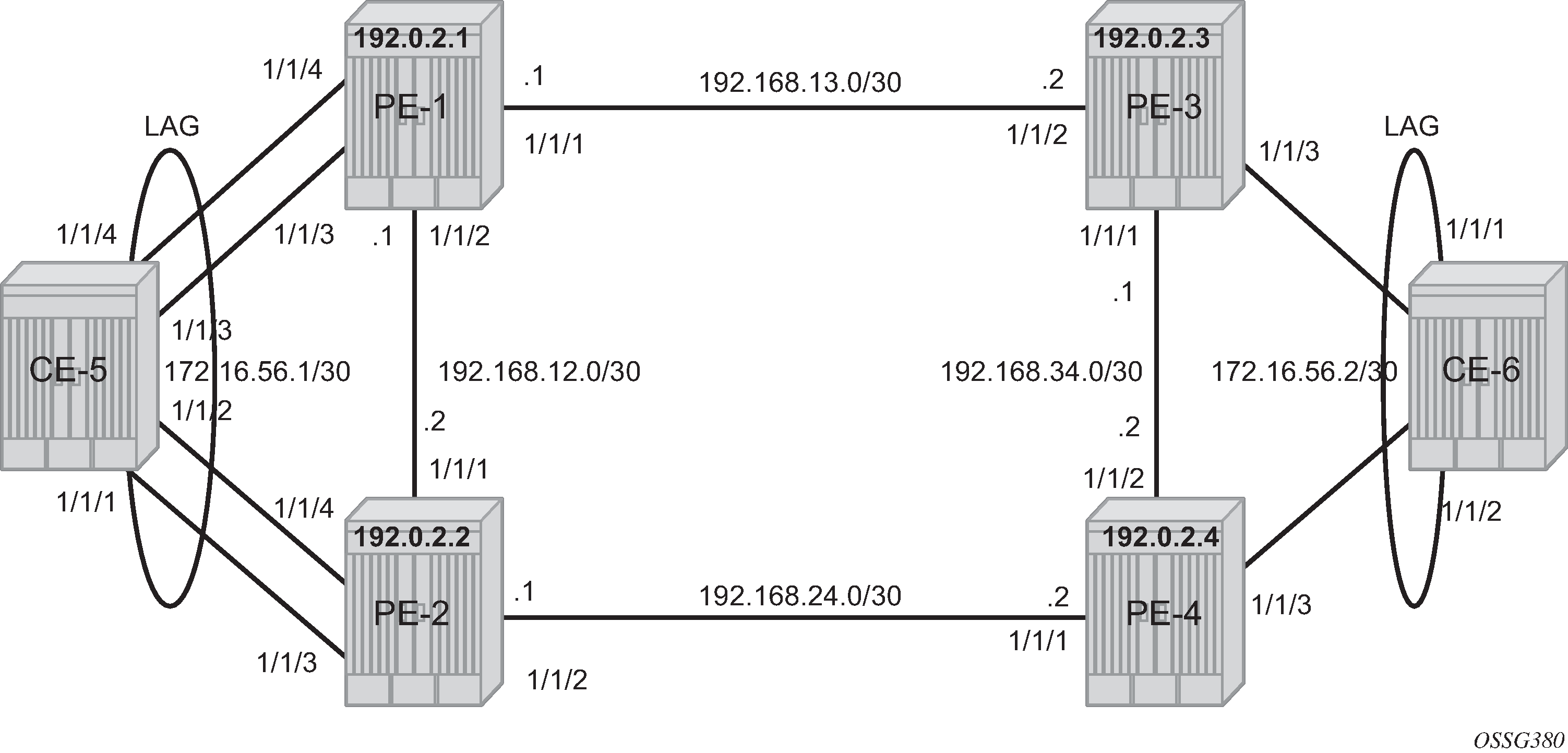
This section describes a setup which contains two CEs and four PEs. The CEs can be any routing/switching device that support the OUT_OF_SYNC signaling as described in IEEE Standard 802.3-2005 section 3 section 43.6.1. MC-LAG example topology shows the physical topology of the setup.
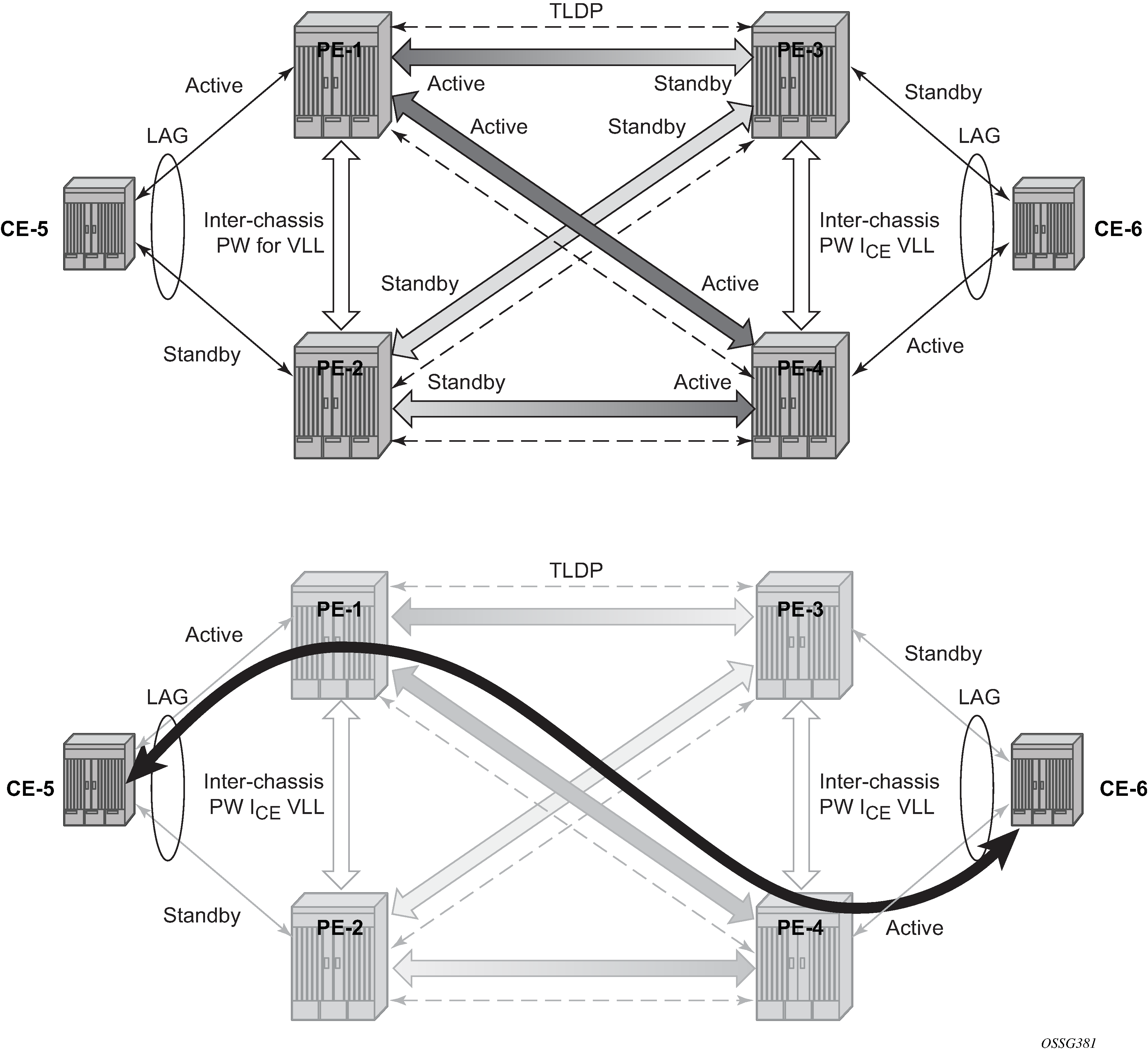
Network resiliency shows the use of both MC-LAG in the access network and pseudowire redundancy in the core network to provide a resilient end-to-end VLL service between CE-5 and CE-6.
When an SDP is in standby, it sends the pseudowire status bit pwFwdingStandby to its peer.
Configuration
It is assumed that the following base configuration has been implemented on the PEs:
Cards, MDAs, and ports
Router interfaces
IGP configured and converged
MPLS
SDPs configured between all PE routers
Either OSPF or IS-IS can be used as the IGP. Also, several protocols can be used for signaling the transport MPLS labels. Alternatively, GRE can be used for the transport tunnels. Likewise, several protocols can be used for signaling the SDPs. In this example, OSPF and LDP are used.
The following command is used to check if OSPF has converged (for example, on PE-1):
*A:PE-1# show router route-table

===============================================================================
Route Table (Router: Base)
===============================================================================
Dest Prefix[Flags]                            Type    Proto     Age        Pref
      Next Hop[Interface Name]                                    Metric
-------------------------------------------------------------------------------
192.0.2.1/32                                  Local   Local     00h16m53s  0
       system                                                       0
192.0.2.2/32                                  Remote  OSPF      00h14m26s  10
       192.168.12.2                                                 1000
192.0.2.3/32                                  Remote  OSPF      00h14m21s  10
       192.168.13.2                                                 1000
192.0.2.4/32                                  Remote  OSPF      00h14m21s  10
       192.168.12.2                                                 2000
192.168.12.0/30                               Local   Local     00h16m53s  0
       int-PE-1-PE-2                                                0
192.168.13.0/30                               Local   Local     00h16m53s  0
       int-PE-1-PE-3                                                0
192.168.24.0/30                               Remote  OSPF      00h14m26s  10
       192.168.12.2                                                 2000
192.168.34.0/30                               Remote  OSPF      00h14m21s  10
       192.168.13.2                                                 2000
-------------------------------------------------------------------------------
No. of Routes: 8
Flags: n = Number of times nexthop is repeated
       B = BGP backup route available
       L = LFA nexthop available
       S = Sticky ECMP requested
===============================================================================
The following command shows that the SDPs are up:
*A:PE-1# show service sdp

============================================================================
Services: Service Destination Points
============================================================================
SdpId  AdmMTU  OprMTU  Far End          Adm  Opr         Del     LSP   Sig
----------------------------------------------------------------------------
12     0       1492    192.0.2.2        Up   Up          MPLS    L     TLDP
13     0       1492    192.0.2.3        Up   Up          MPLS    L     TLDP
14     0       1492    192.0.2.4        Up   Up          MPLS    L     TLDP
----------------------------------------------------------------------------
Number of SDPs : 3
----------------------------------------------------------------------------
Legend: R = RSVP, L = LDP, B = BGP, M = MPLS-TP, n/a = Not Applicable
        I = SR-ISIS, O = SR-OSPF, T = SR-TE, F = FPE
============================================================================
MC-LAG for Epipe services
Step 1 - MC-LAG configuration on CEs.
The LAG configuration on the CEs is only included for completeness; any CE device could be used.
Auto-negotiation must be switched off or set to limited on all ports that will be included into the LAG in order to guarantee a specific port speed.
Disabling autonegotiation on Gigabit ports is not allowed because the IEEE 802.3 specification for Gigabit Ethernet requires autonegotiation to be enabled for far end fault detection.
Configure LACP on the LAG with at least one side of the LAG in active mode.
*A:CE-5# configure port 1/1/[1..4] ethernet autonegotiate limited
*A:CE-5# configure port 1/1/[1..4] no shutdown

# on CE-5:
configure
    lag 1
        port 1/1/1
        port 1/1/2
        port 1/1/3
        port 1/1/4
        lacp active administrative-key 32768
        no shutdown
    exit
exit
Step 2 - LAG configuration on PEs.
The PE ports connected to the CEs must be configured as access ports because they will be used in the redundant pseudowire service. The LAG must also be configured in access mode.
The LAG encapsulation type (null | dot1q | qinq) must match the port encapsulation type of the LAG members.
Auto-negotiation must be switched off or configured to limited.
Configure LACP on the LAG. At least 1 side of the LAG (PE or CE) must be configured in active mode.
# on PE-1:
configure
    port 1/1/3
        ethernet
            mode access
            autonegotiate limited
        exit
        no shutdown
    exit
    port 1/1/4
        ethernet
            mode access
            autonegotiate limited
        exit
        no shutdown
    exit
    lag 1
        mode access
        port 1/1/3
        port 1/1/4
        lacp active administrative-key 32768
        no shutdown
    exit
exit
Step 3 - MC-LAG configuration on PE-1 and PE-2
The redundant PEs must act as one virtual node toward the CE. They have to be able to communicate the same LACP parameters to the CE side.
The following parameters uniquely identify a LAG instance:
lacp-key
system-id
system-priority
These three parameters must be configured with the same value on both redundant PEs.
Multi-chassis redundancy requires a peering session (which operates by an IP connection using UDP destination port 1025) that is configured toward the redundant PE system address to which MC-LAG redundancy is enabled, as follows. The peering session can be configured with MD5 authentication.
# on PE-1:
configure
    redundancy
        multi-chassis
            peer 192.0.2.2 create
                authentication-key "GBeGhtqKlY06VZKF2QK+xAzSig==" hash2
                mc-lag
                    lag 1 lacp-key 1 system-id 00:00:00:00:00:01 system-priority 100
                    no shutdown
                exit
                no shutdown
            exit
# on PE-2:
configure
    redundancy
        multi-chassis
            peer 192.0.2.1 create
                authentication-key "GBeGhtqKlY06VZKF2QK+xF3iEg==" hash2
                mc-lag
                    lag 1 lacp-key 1 system-id 00:00:00:00:00:01 system-priority 100
                    no shutdown
                exit
                no shutdown
            exit
Step 4 - MC-LAG verification.
Verify MC peers showing that the authentication and admin state are enabled.
*A:PE-1# show redundancy multi-chassis sync

===============================================================================
Multi-chassis Peer Table
===============================================================================
Peer
-------------------------------------------------------------------------------
Peer IP Address         : 192.0.2.2
Description             : (Not Specified)
Authentication          : Enabled
Source IP Address       : 192.0.2.1
Admin State             : Enabled
Warm standby            : No
Remote warm standby     : No
-------------------------------------------------------------------------------
Sync: Not-configured
-------------------------------------------------------------------------------
===============================================================================
===============================================================================
Step 5 - Verify MC-LAG peer status and LAG parameters.
*A:PE-1# show redundancy multi-chassis mc-lag peer 192.0.2.2

===============================================================================
Multi-Chassis MC-Lag Peer 192.0.2.2
===============================================================================
Last State chg  : 01/07/2020 12:33:32
Admin State     : Up                  Oper State           : Up
KeepAlive       : 10 deci-seconds     Hold On Ngbr Failure : 3
-------------------------------------------------------------------------------
Lag Id Lacp   Remote Source Oper   System Id          Sys   Last State Changed
       Key    Lag Id MacLSB MacLSB                    Prio
-------------------------------------------------------------------------------
1      1      1      Def    n/a    00:00:00:00:00:01  100   01/07/2020 12:33:33
-------------------------------------------------------------------------------
Number of LAGs : 1
===============================================================================
There is a fixed keepalive timer of 1 second. The hold-on-neighbor-failure multiplier command indicates the interval that the standby node will wait for packets from the active node before assuming a redundant-neighbor failure. The hold-on-neighbor-failure <multiplier> command is configurable in the config>redundancy>multi-chassis>peer>mc-lag context. The standby node will also assume a redundant-neighbor failure when there is no route available to the redundant-neighbor.
# on PE-1:
configure
    redundancy
        multi-chassis
            peer 192.0.2.2
                mc-lag
                    hold-on-neighbor-failure 10
                exit
            exit
        exit
    exit
In this example, the lag-id is 1 on both redundant PEs. This is not mandatory. If the lag-id on PE-2 is, for example 2, the following should be configured on PE-1:
# on PE-1:
configure
    redundancy
        multi-chassis
            peer 192.0.2.2
                mc-lag
                    lag 1 lacp-key 1 system-id 00:00:00:00:00:01 remote-lag 2
                exit
            exit
        exit
    exit
Step 6 - Verify MC-LAG
*A:PE-1# show lag 1
===============================================================================
Lag Data
===============================================================================
Lag-id         Adm     Opr     Weighted Threshold Up-Count MC Act/Stdby
-------------------------------------------------------------------------------
1              up      up      No       0         2        active
===============================================================================
*A:PE-2# show lag 1
===============================================================================
Lag Data
===============================================================================
Lag-id         Adm     Opr     Weighted Threshold Up-Count MC Act/Stdby
-------------------------------------------------------------------------------
1              up      down    No       0         0        standby
===============================================================================
In this case, the LAG on PE-1 is active (operationally up) whereas the LAG on PE-2 is standby (operationally down).
The default selection criteria is highest number of links and priority. In this example, the number of links and the priority of the links is the same on both redundant PEs. Whichever PE’s LAG gets the operational status up first, will be the active LAG.
LAG ports of one PE could be preferred over the other PE by configuring port priority. For example, the following command lowers the priority of the LAG ports on PE-1, thus giving this LAG higher preference. The default priority is 32768, but it is modified to a value of 10, as follows:
# on PE-1:
configure
    lag 1
        port 1/1/3 priority 10
        port 1/1/4 priority 10
The selection criteria can be configured as highest-count, highest-weight or best-port (the default is highest count).
*A:PE-1# configure lag 1 selection-criteria
  - selection-criteria [best-port|highest-count|highest-weight] [slave-to-partner]     [subgroup-hold-time <hold-time>]
  - no selection-criteria

 <best-port|highest*> : keywords
 <slave-to-partner>   : keyword
 <hold-time>          : [0..2000] tenths of a second | infinite
If highest-weight is configured, the sum of the weights of the LAG members is considered. The weight of an individual LAG member is calculated as priority 65535 (the default is 32768).
Step 7 - Verify detailed MC-LAG status on PE-1
*A:PE-1# show lag 1 detail

===============================================================================
LAG Details
===============================================================================
Description        : N/A
-------------------------------------------------------------------------------
Details
-------------------------------------------------------------------------------
Lag-id              : 1                     Mode                 : access
Adm                 : up                    Opr                  : up
Thres. Last Cleared : 01/07/2020 12:42:16   Thres. Exceeded Cnt  : 0
Dynamic Cost        : false                 Encap Type           : null
Configured Address  : 04:0f:ff:00:01:41     Lag-IfIndex          : 1342177281
Hardware Address    : 04:0f:ff:00:01:41     Adapt Qos (access)   : distribute
Hold-time Down      : 0.0 sec               Port Type            : standard
Per-Link-Hash       : disabled
Include-Egr-Hash-Cfg: disabled              Forced               : -
Per FP Ing Queuing  : disabled              Per FP Egr Queuing   : disabled
Per FP SAP Instance : disabled
Access Bandwidth    : N/A                   Access Booking Factor: 100
Access Available BW : 0
Access Booked BW    : 0
LACP                : enabled               Mode                 : active
LACP Transmit Intvl : fast                  LACP xmit stdby      : enabled
Selection Criteria  : highest-count         Slave-to-partner     : disabled
MUX control         : coupled
Subgrp hold time    : 0.0 sec               Remaining time       : 0.0 sec
Subgrp selected     : 1                     Subgrp candidate     : -
Subgrp count        : 1
System Id           : 04:0f:ff:00:00:00     System Priority      : 32768
Admin Key           : 32768                 Oper Key             : 1
Prtr System Id      : 04:1f:ff:00:00:00     Prtr System Priority : 32768
Prtr Oper Key       : 32768
Standby Signaling   : lacp
Port hashing        : port-speed            Port weight speed    : 0 gbps
Ports Up            : 2
Weights Up          : 2                     Hash-Weights Up      : 2
Monitor oper group  : N/A

MC Peer Address     : 192.0.2.2             MC Peer Lag-id       : 1
MC System Id        : 00:00:00:00:00:01     MC System Priority   : 100
MC Admin Key        : 1                     MC Active/Standby    : active
MC Lacp ID in use   : true                  MC extended timeout  : false
MC Selection Logic  : local master decided
MC Config Mismatch  : no mismatch

-------------------------------------------------------------------------------
Port-id        Adm     Act/Stdby Opr     Primary   Sub-group     Forced  Prio
-------------------------------------------------------------------------------
1/1/3          up      active    up      yes       1             -       10
1/1/4          up      active    up                1             -       10

-------------------------------------------------------------------------------
Port-id        Role      Exp   Def   Dist  Col   Syn   Aggr  Timeout  Activity
-------------------------------------------------------------------------------
1/1/3          actor     No    No    Yes   Yes   Yes   Yes   Yes      Yes
1/1/3          partner   No    No    Yes   Yes   Yes   Yes   Yes      Yes
1/1/4          actor     No    No    Yes   Yes   Yes   Yes   Yes      Yes
1/1/4          partner   No    No    Yes   Yes   Yes   Yes   Yes      Yes
===============================================================================
After changing the LAG port priorities from default (32768) to 10, the LAG on PE-1 is in up/up state and the ports are in up/active/up status. This show command also displays actor and partner bits set in the LACP messages.
Step 8 - MC-LAG configuration on PE-3 and PE-4.
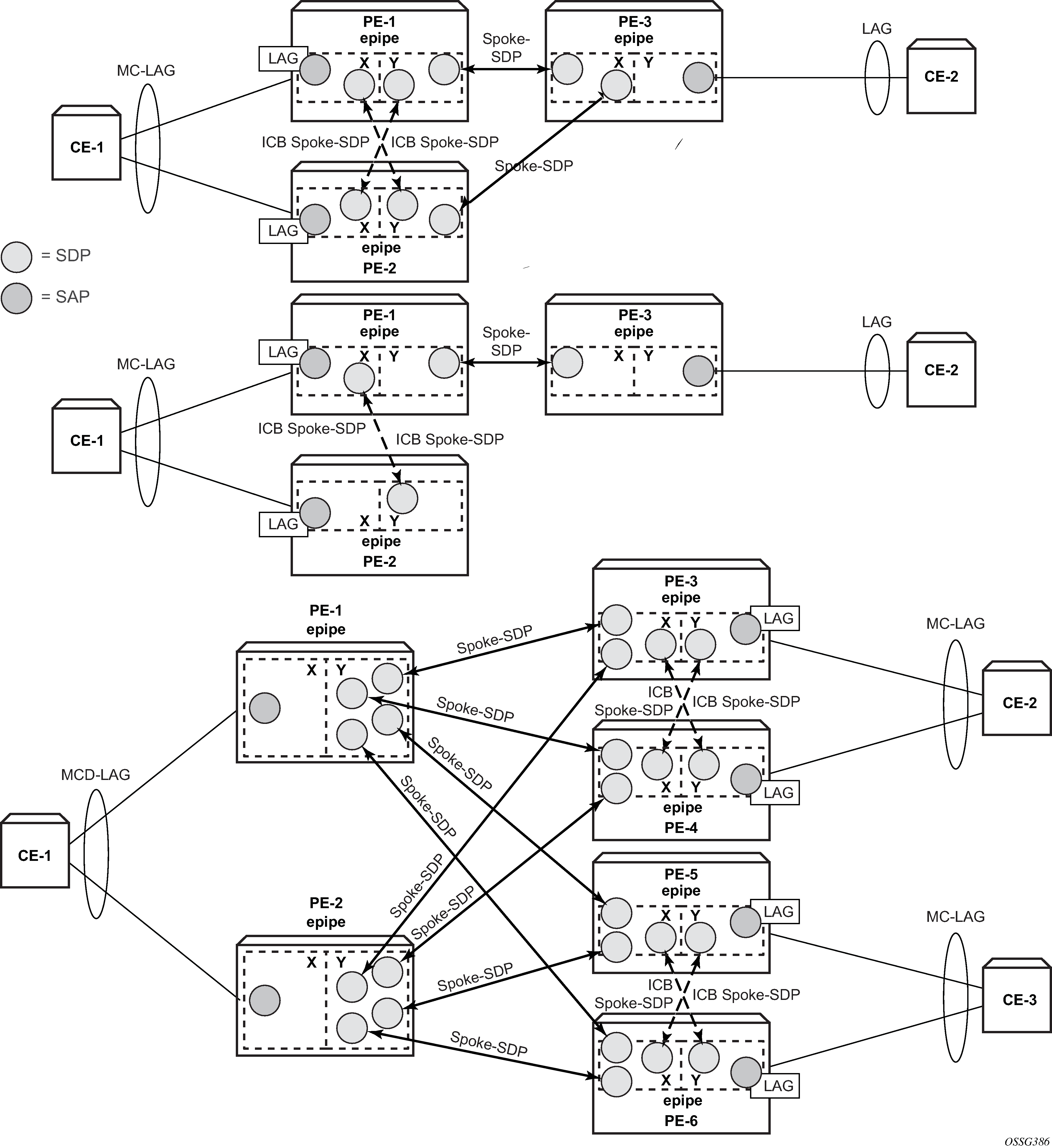
The MC-LAG configuration on PE-3 and PE-4 is similar to the configuration on PE-1 and PE-2. In this case, the priority of the LAG port on PE-4 is lowered to obtain the behavior in Network resiliency where the LAGs on PE-1 and PE-4 are active.
Step 9 - Pseudowire configuration.
Configure an Epipe service on every PE and create endpoints X and Y (the endpoint names can be any text string). Traffic can only be forwarded between two endpoints, for example, it is not possible for objects associated with the same endpoint to forward traffic to each other.
Associate the SAPs and spoke SDPs with the endpoints as shown in Association of SAPs/SDPs and endpoints.
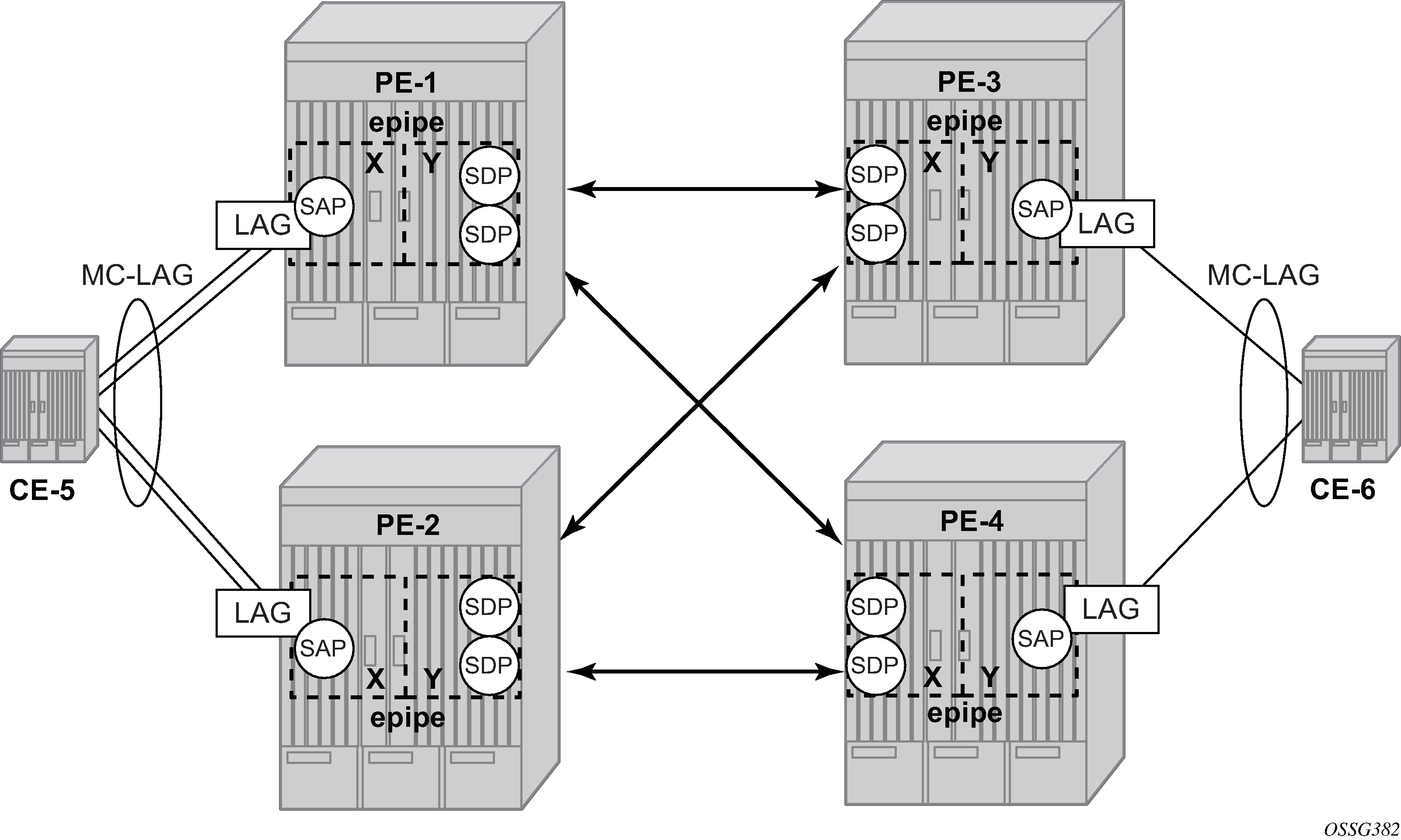
# on PE-1:
configure
    service
        epipe 1 name "Epipe 1" customer 1 create
            endpoint "X" create
            exit
            endpoint "Y" create
            exit
            service-mtu 1400
            sap lag-1 endpoint "X" create
            exit
            spoke-sdp 13:1 endpoint "Y" create
            exit
            spoke-sdp 14:1 endpoint "Y" create
            exit
            no shutdown
        exit
    exit
exit
Likewise, an Epipe service, endpoints, SAPs and spoke SDPs must be configured on the other PE routers.
Step 10 - Pseudowire verification.
*A:PE-1# show service service-using

===============================================================================
Services
===============================================================================
ServiceId    Type      Adm  Opr  CustomerId Service Name
-------------------------------------------------------------------------------
1            Epipe     Up   Up   1          Epipe 1
2147483648   IES       Up   Down 1          _tmnx_InternalIesService
2147483649   intVpls   Up   Down 1          _tmnx_InternalVplsService
-------------------------------------------------------------------------------
Matching Services : 3
-------------------------------------------------------------------------------
===============================================================================
*A:PE-2# show service service-using

===============================================================================
Services
===============================================================================
ServiceId    Type      Adm  Opr  CustomerId Service Name
-------------------------------------------------------------------------------
1            Epipe     Up   Down 1          Epipe 1
2147483648   IES       Up   Down 1          _tmnx_InternalIesService
2147483649   intVpls   Up   Down 1          _tmnx_InternalVplsService
-------------------------------------------------------------------------------
Matching Services : 3
-------------------------------------------------------------------------------
===============================================================================
*A:PE-3# show service service-using

===============================================================================
Services
===============================================================================
ServiceId    Type      Adm  Opr  CustomerId Service Name
-------------------------------------------------------------------------------
1            Epipe     Up   Down 1          Epipe 1
2147483648   IES       Up   Down 1          _tmnx_InternalIesService
2147483649   intVpls   Up   Down 1          _tmnx_InternalVplsService
-------------------------------------------------------------------------------
Matching Services : 3
-------------------------------------------------------------------------------
===============================================================================
*A:PE-4# show service service-using

===============================================================================
Services
===============================================================================
ServiceId    Type      Adm  Opr  CustomerId Service Name
-------------------------------------------------------------------------------
1            Epipe     Up   Up   1          Epipe 1
2147483648   IES       Up   Down 1          _tmnx_InternalIesService
2147483649   intVpls   Up   Down 1          _tmnx_InternalVplsService
-------------------------------------------------------------------------------
Matching Services : 3
-------------------------------------------------------------------------------
===============================================================================
The Epipe service on PE-2 and PE-3 is down and up on PE-1 and PE-4. This reflects the standby behavior shown in Network resiliency. However, after configuring ICB spoke SDPs (described later in this chapter), the Epipe will be in up/up status on all PE routers.
Step 11 - Verify SDP status
Local pseudowire bits indicate the status of the pseudowire on the PE node. These pseudowire bits will be sent to the peer. Peer pseudowire bits indicate the status of the pseudowire on the peer, as sent by the peer. The following example is taken on PE-2:
*A:PE-2# show service id 1 sdp 23:1 detail

===============================================================================
Service Destination Point (Sdp Id : 23:1) Details
===============================================================================
-------------------------------------------------------------------------------
 Sdp Id 23:1  -(192.0.2.3)
-------------------------------------------------------------------------------
Description     : (Not Specified)
SDP Id             : 23:1                     Type              : Spoke
Spoke Descr     : (Not Specified)
VC Type            : Ether                    VC Tag            : n/a
Admin Path MTU     : 0                        Oper Path MTU     : 1492
Delivery           : MPLS
Far End            : 192.0.2.3                Tunnel Far End    :
Oper Tunnel Far End: 192.0.2.3
LSP Types          : LDP
Hash Label         : Disabled                 Hash Lbl Sig Cap  : Disabled
Oper Hash Label    : Disabled
Entropy Label      : Disabled

Admin State        : Up                       Oper State        : Up
MinReqd SdpOperMTU : 1400
Acct. Pol          : None                     Collect Stats     : Disabled
Ingress Label      : 524283                   Egress Label      : 524282
Ingr Mac Fltr-Id   : n/a                      Egr Mac Fltr-Id   : n/a
Ingr IP Fltr-Id    : n/a                      Egr IP Fltr-Id    : n/a
Ingr IPv6 Fltr-Id  : n/a                      Egr IPv6 Fltr-Id  : n/a
Admin ControlWord  : Not Preferred            Oper ControlWord  : False
Admin BW(Kbps)     : 0                        Oper BW(Kbps)     : 0
BFD Template       : None
BFD-Enabled        : no                       BFD-Encap         : ipv4
Last Status Change : 01/07/2020 12:51:04      Signaling         : TLDP
Last Mgmt Change   : 01/07/2020 12:50:53
Endpoint           : Y                        Precedence        : 4
PW Status Sig      : Enabled
Force Vlan-Vc      : Disabled                 Force Qinq-Vc     : none
Class Fwding State : Down
Flags              : None
Local Pw Bits      : lacIngressFault lacEgressFault pwFwdingStandby
Peer Pw Bits       : lacIngressFault lacEgressFault pwFwdingStandby
Peer Fault Ip      : None
Peer Vccv CV Bits  : lspPing bfdFaultDet
Peer Vccv CC Bits  : mplsRouterAlertLabel

---snip---

-------------------------------------------------------------------------------
Segment Routing
-------------------------------------------------------------------------------
ISIS               : disabled
OSPF               : disabled
TE-LSP             : disabled
-------------------------------------------------------------------------------
Number of SDPs : 1
-------------------------------------------------------------------------------
===============================================================================
In this example, the remote side of the SDP is sending lacIngressFault lacEgressFault pwFwdingStandby flags. This is because the Epipe service on PE-3 is down because the MC-LAG is in standby/down status.
Link and node protection can be tested. The access links are protected by the MC-LAG, the PE routers are protected by the combination of MC-LAG/pseudowire redundancy. The SDPs can be protected by FRR, unless GRE is used.
Revertive behavior is expected when different MC-LAG port priorities are configured or if the number of MC-LAG ports is different on the MC-LAG peers: convergence takes place when the active PE fails and convergence takes place again when that PE is online again.
In case of revertive behavior, MC-LAG convergence might take less time than the setup of the spoke SDPs, thus creating a temporary black-hole. To avoid this situation, it is best to configure hold-time up on the LAG ports. In that case, the ports are kept in a down state for a configured period of time after the node has rebooted. This is done to ensure that the SDPs are operationally up when the MC-LAG convergence takes place. The hold-time up is expressed in seconds.
# on PE-1:
configure
    port 1/1/3
        ethernet
            hold-time up 50
        exit
    exit
    port 1/1/4
        ethernet
            hold-time up 50
        exit
    exit
Step 12 - Inter-Chassis Backup (ICB) pseudowire configuration.
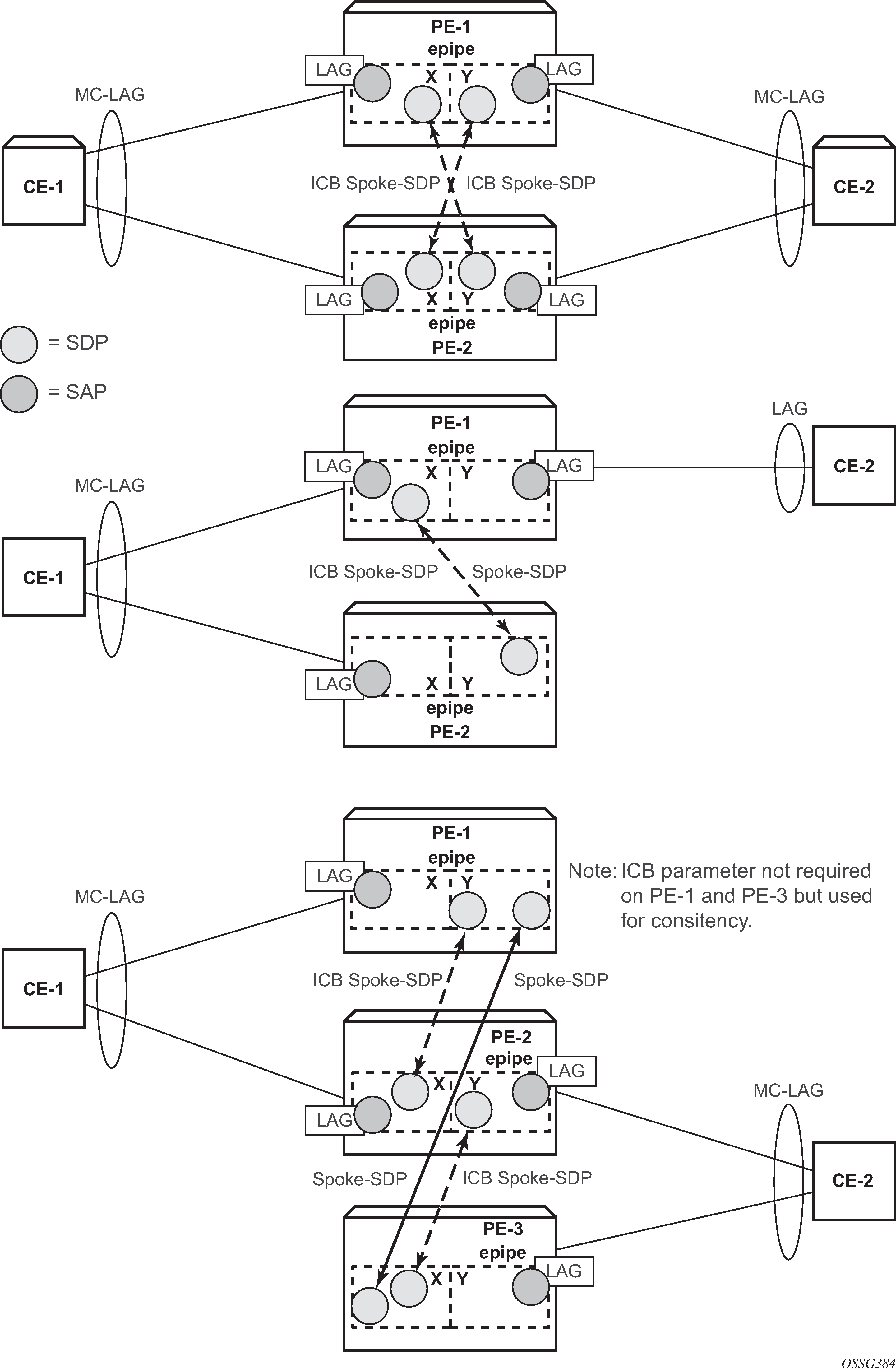
In this setup, the configuration of ICBs is optional. It can be used to speed up convergence by forwarding in-flight packets during MC-LAG transition. Additional setup example 1 shows some setup examples where ICBs are required. ICBs cannot be configured at endpoints where the other object is a standard SAP, only MC-LAG SAPs and pseudowires are allowed with ICBs.
ICB SDPs and associated to endpoints as shown in ICB spoke SDPs and their association with the endpoints.
Two ICB spoke SDPs must be configured in the Epipe service on each PE router, one in each endpoint. Different SDP IDs can be used for the ICBs (as opposed to the regular pseudowires), but this is not necessary, because the far-end will be the same. The vc-id must be different however.
The ICB spoke SDPs must cross, one end should be associated with endpoint X and the other end (on the other PE) should be associated with endpoint Y. After configuring the ICB spoke SDPs, the Epipe service will be up/up on all four PE routers.
Only one spoke SDP will be forwarding. If there is an ICB and a MC-LAG SAP in an endpoint, the ICB will only forward if the SAP goes down. If an ICB resides in an endpoint together with other spoke SDPs, the ICB will only forward if there is no other active spoke SDP.
The following output shows the additional Epipe service configuration on each PE:
# on PE-1:
configure
    service
        epipe 1
            spoke-sdp 12:1 endpoint "X" icb create
            exit
            spoke-sdp 12:2 endpoint "Y" icb create
            exit
# on PE-2:
configure
    service
        epipe 1
            spoke-sdp 21:1 endpoint "Y" icb create
            exit
            spoke-sdp 21:2 endpoint "X" icb create
            exit
# on PE-3:
configure
    service
        epipe 1
            spoke-sdp 34:1 endpoint "X" icb create
            exit
            spoke-sdp 34:2 endpoint "Y" icb create
            exit
# on PE-4:
configure
    service
        epipe 1
            spoke-sdp 43:1 endpoint "Y" icb create
            exit
            spoke-sdp 43:2 endpoint "X" icb create
            exit
Step 13 - Verification of active objects for each endpoint.
The following command shows which objects are configured for each endpoint and which is the active object at this moment:
*A:PE-1# show service id 1 endpoint

===============================================================================
Service 1 endpoints
===============================================================================
Endpoint name                : X
Description                  : (Not Specified)
Creation Origin              : manual
Revert time                  : 0
Act Hold Delay               : 0
Standby Signaling Master     : false
Standby Signaling Slave      : false
Tx Active                    : lag-1
Tx Active Up Time            : 0d 00:09:47
Revert Time Count Down       : never
Tx Active Change Count       : 1
Last Tx Active Change        : 01/07/2020 12:49:52
-------------------------------------------------------------------------------
Members
-------------------------------------------------------------------------------
SAP      : lag-1                                    Oper Status: Up
Spoke-sdp: 12:1 Prec:4 (icb)                        Oper Status: Up
===============================================================================
Endpoint name                : Y
Description                  : (Not Specified)
Creation Origin              : manual
Revert time                  : 0
Act Hold Delay               : 0
Standby Signaling Master     : false
Standby Signaling Slave      : false
Tx Active (SDP)              : 14:1
Tx Active Up Time            : 0d 00:06:02
Revert Time Count Down       : never
Tx Active Change Count       : 2
Last Tx Active Change        : 01/07/2020 12:53:37
-------------------------------------------------------------------------------
Members
-------------------------------------------------------------------------------
Spoke-sdp: 12:2 Prec:4 (icb)                        Oper Status: Up
Spoke-sdp: 13:1 Prec:4                              Oper Status: Up
Spoke-sdp: 14:1 Prec:4                              Oper Status: Up
===============================================================================
===============================================================================
On PE-1, the SAP and the spoke SDP 14:1 are active. The other objects do not forward traffic.
Step 14 - Other types of setups.
Additional setup example 1 and Additional setup example 2 show other setups that combine MC-LAG and pseudowire redundancy.
MC-LAG for VPLS services
MC-LAG can also be configured for VPLS services. When the MC-LAG converges, the PE that transitions to standby state for the MC-LAG will send out an LDP address withdrawal message to all peers configured in the VPLS service. Both types of SDPs (spoke and mesh) support this feature. The PE peers will then flush all the MAC addresses learned via the PE that sent the LDP MAC address withdrawal message.
Because a VPLS service is a multipoint service, pseudowire redundancy is not required. The MC-LAG redundancy configuration is identical.
Forced switchover
MC-LAG convergence can be forced with the tools perform lag command:
*A:PE-1# tools perform lag force
  - force all-mc {active|standby}
  - force lag-id <lag-id> [sub-group <sub-group-id>] {active|standby}
  - force peer-mc <ip-address> {active|standby}

 <lag-id>             : [1..800]
 <sub-group-id>       : [1..16]
 <all-mc>             : keyword
 <ip-address>         : ipv4-address   - a.b.c.d
                        ipv6-address   - x:x:x:x:x:x:x:x   (eight 16-bit pieces)
                                         x:x:x:x:x:x:d.d.d.d
                                         x - [0..FFFF]H
                                         d - [0..255]D
 <active|standby>     : keywords
*A:PE-1# tools perform lag force lag-id 1 standby
*A:PE-1# show lag 1

===============================================================================
Lag Data
===============================================================================
Lag-id         Adm     Opr     Weighted Threshold Up-Count MC Act/Stdby
-------------------------------------------------------------------------------
1              up      down    No       0         0        standby
===============================================================================
After the forced switchover, it is important to clear the forced switchover:
*A:PE-1# tools perform lag clear-force
  - clear-force all-mc
  - clear-force lag-id <lag-id> [sub-group <sub-group-id>]
  - clear-force peer-mc <ip-address>

 <lag-id>             : [1..800]
 <sub-group-id>       : [1..16]
 <all-mc>             : keyword
 <ip-address>         : ipv4-address   - a.b.c.d
                        ipv6-address   - x:x:x:x:x:x:x:x   (eight 16-bit pieces)
                                         x:x:x:x:x:x:d.d.d.d
                                         x - [0..FFFF]H
                                         d - [0..255]D
*A:PE-1# tools perform lag clear-force lag-id 1
*A:PE-1# show lag 1

===============================================================================
Lag Data
===============================================================================
Lag-id         Adm     Opr     Weighted Threshold Up-Count MC Act/Stdby
-------------------------------------------------------------------------------
1              up      up      No       0         2        active
===============================================================================
Conclusion
MC-LAG is a Nokia added value redundancy feature that offers fast access link convergence in Epipe and VPLS services for CE devices that support standard LACP. PE node convergence for VPLS services is enhanced by using LDP address withdrawal messages to flush the FDB on the PE peers. PE node convergence for Epipes is guaranteed by using pseudowire redundancy.