IEEE 1588 for Frequency, Phase, and Time Distribution
This chapter provides information about IEEE 1588 for frequency, phase, and time distribution.
Topics in this chapter include:
Applicability
The information and configuration in this chapter are based on SR OS Release 12.0.R2. The only software prerequisites are IP reachability between the node and neighboring IEEE 1588 clocks.
IEEE 1588 has several hardware dependencies both for the basic functionality as well as the IEEE 1588 port based timestamping necessary for high accuracy time distribution. Please consult the related Nokia documentation for the details of all the hardware requirements.
Overview
Defined in IEEE Std 1588™-2008 (1588v2), Precision Time Protocol (PTP) is a protocol that distributes frequency, phase and time over packet based networks.
Many applications do not need time alignment but only phase alignment. However, phase is derived from time and so, for the remainder of the document, discussion refers to time but those references imply both time and phase.
The IEEE 1588 protocol has become the standard for distribution of high accuracy time. Following guidelines for specific network architectures allows the delivery of time to accuracies of one microsecond. This level of accuracy is required for mobile base stations using either Time Division Duplex technology and/or advanced LTE functions, as well as in the power industry for intelligent electronic device alignment.
More lenient architectures can still achieve 100 microseconds or better accuracies which can greatly enhance the usefulness of event logging and network one way delay measurements.
In addition, IEEE 1588 has been used to deliver a frequency reference for T1/E1 ports or for mobile base station frequency alignment. This is useful in environments where the transport network does not provide physical layer synchronization services.
The following IEEE 1588 capabilities are provided within the 7750 SR and 7450 ESS nodes:
CPM/CFM based IEEE 1588 timeTransmitter, boundary, and timeReceiver clock functionality
Transport over Unicast UDP/IPv4 packets
Access to IEEE 1588 process through base routing, IES, and VPRNs
Port based timestamping of IEEE 1588 packets
IEEE 1588 Profiles: 2008 standard default and ITU-T G.8265.1
Utilization of IEEE 1588 derived time for NTP and System time.
PTP Basics
PTP uses an exchange of four timestamps between a reference clock (timeTransmitter port) and the clock to be synchronized (timeReceiver port). A simplified illustration of this mechanism is shown in PTP Messages and Timestamp Exchange.
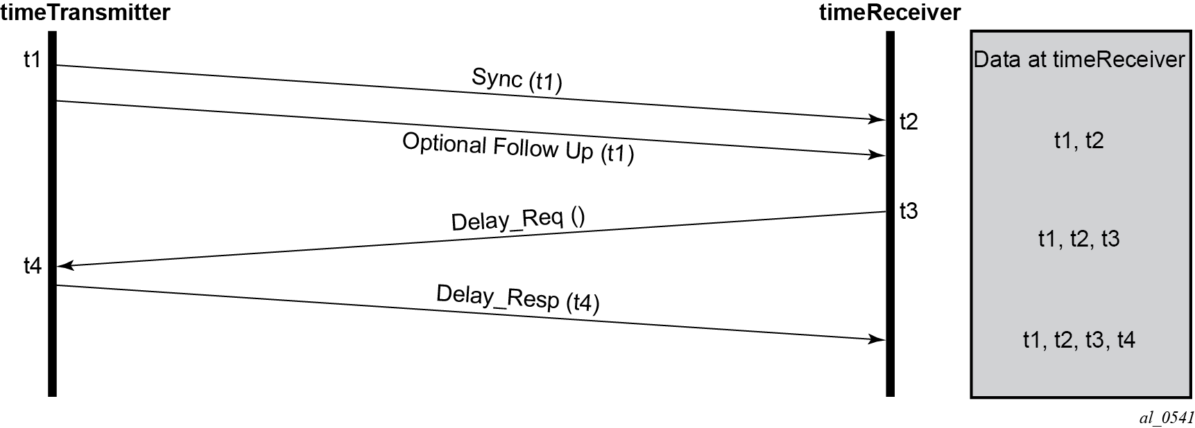
The timeTransmitter sends a PTP Sync message containing a timestamp of when the Sync message is transmitted (t1) to the timeReceiver. In a two-step timeTransmitter clock, the t1 timestamp is sent in a Follow_Up message. The timeReceiver records the time it receives the Sync message (t2). At some point after receiving the Sync message, the timeReceiver sends a Delay_Req message back to the timeTransmitter. The timeReceiver records the time of transmission of the Delay_Req message (t3) locally. The timeTransmitter records the time it receives the Delay_Req message (t4) and sends this timestamp back to the timeReceiver in a Delay_Resp message.
The Follow_Up message was defined to allow for implementations to generate a timestamp for the transmission of the Sync message but not have to try to insert that timestamp into the Sync message and update any frame checksums on the fly as it is in the process of transmission. While many recent implementations can perform the timestamping, update and checksum calculation on the fly, not all devices could perform this three step process with the desired accuracy. By using the Follow_Up message to transmit the timestamp of the Sync message, the timeTransmitter port can still provide extremely accurate timestamps for the transmission of the Sync message to the timeReceiver port. Apart from the extra message required, there is no detriment to a timeTransmitter port using one-step clock versus a two-step clock procedures. All PTP clocks that have timeReceiver port capability must accept timing information from both types of timeTransmitter port. There is no requirement to force a clock that is a one-step clock to use two-step clock procedures on its timeTransmitter ports. The nodes covered by this example all support one-step clock timeTransmitter port procedures.
After the four timestamp exchange the timeReceiver can calculate the mean path delay and the clock offset from timeTransmitter using the following two equations:
mean_path_delay = [(t4 – t1) – (t3 – t2)] /2
offset_from_timeTransmitter = [(t2 – t1) – mean_path_delay]
These calculations can occur on every message exchange or some initial packet selection can be performed so that only optimal message exchanges are used. The latter is useful if there is variable delay between the timeTransmitter and timeReceiver ports.
If only frequency is necessary, then the timeReceiver may use one or both pairs of timestamps (t1, t2) and (t3, t4). The timeReceiver can monitor the change in the perceived delay timeTransmitter-to-timeReceiver (t2 – t1) or timeReceiver-to-timeTransmitter (t4 – t3) over time. If the delay (t2 – t1) decreases over time, it means the t2 timestamps are not progressing quickly enough and the timeReceiver clock frequency needs to be increased.
If time is necessary, then all four timestamps must be used. It is also important to note how the equation for offset uses the mean_path_delay. If the delays in the two directions are actually different, then the equation will introduce an error in the offset_from_timeTransmitter that is half of the difference of the two delays. The IEEE 1588 standard includes procedures to compensate for this asymmetry, if it is known, but if it is uncompensated, it does introduce time error.
PTP Deployment Architectures
It is important to understand that there are very different topologies recommended for using IEEE 1588 for frequency distribution and using IEEE 1588 for time distribution.
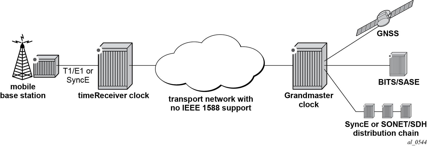
Frequency distribution was developed for an architecture where there are mobile providers who have points of presence at the mobile telephony switching offices (MTSOs) and the cell site locations which depend on other parties for the connectivity between the MTSOs and the cell site locations. The mobile providers wanted a solution that could span the transport networks with minimal dependence on that network. This can be achieved by placing an IEEE 1588 grandmaster at the MTSO and a timeReceiver in a cell site router or directly in the base station and distributing the timestamped packets between the two, as shown in IEEE 1588 Topology for Frequency Distribution. The transport network does introduce packet delay variation (PDV) to the IEEE 1588 messages which makes it more difficult to track the frequency of the grandmaster’s clock. However, the timeReceivers have been designed to perform packet selection and noise filtering to allow for the recovery of a frequency within the required accuracies of the mobile base stations. This architecture and the performance requirements are covered by the ITU-T G.826x series of recommendations.

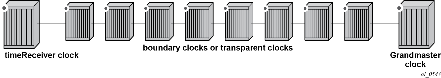
For time distribution, it has been recognized that the architecture used above is extremely unlikely to be successful. The fundamental reason is that the performance requirement is much tighter and the network introduces not only PDV but also potentially asymmetric delay which causes time error in the timeReceiver. The topology recommended for time distribution is what is sometimes referred to as ‟Full On-Path Support (OPS)”. Full OPS means that every network element between the grandmaster clock and the timeReceiver clock is either an IEEE 1588 boundary clock or a IEEE 1588 transparent clock, as shown in IEEE 1588 Topology for Time Distribution. Boundary clocks and transparent clocks process the IEEE 1588 messages and remove the PDV noise that would be present in a non IEEE 1588 network element. By using network elements that have very tight constraints on the time error they introduced, the network can be built to guarantee time accuracy under all network traffic conditions. This architecture and the performance requirements are covered by the ITU-T G.827x series of recommendations.
PTP Profiles
The IEEE 1588v2 standard includes the concept of a PTP profile. A PTP profile allows standardization bodies or industry groups to adapt the IEEE 1588v2 standard to a particular application. A profile defines which aspects of the IEEE 1588v2 standard are included or excluded, along with configurable ranges and defaults necessary for the application.
The IEEE 1588 standard itself includes a default profile that can be used for either time or frequency distribution. The default profile was defined principally for multicast operation. However, it can be used with the unicast sessions as described below. The default profile supports all IEEE 1588 clock types and includes the Best Master Clock Algorithm (BMCA) that automatically builds the synchronization distribution hierarchy amongst the PTP clocks. The SR OS only supports the unicast session version of the default profile.
In the telecommunications industry, the ITU-T is the body that develops these profiles. They have generated a profile for frequency distribution (G.8265.1) and a profile for time distribution (G.8275.1). The frequency profile permits only grandmaster and timeReceiver clocks and can be used to extended a traditional physical layer synchronization distribution (SONET/SDH, PDH, or SyncE) with a final leg of IEEE 1588 messages. The frequency source of the IEEE 1588 grandmaster could be a GPS receiver, a central office BITS or SASE device or it could use the frequency recovered from a Synchronous Ethernet or SONET/SDH interface. This is shown in Frequency Distribution with IEEE 1588 as Last Mile
Because an IEEE 1588 distribution system is significantly noisier than a physical layer distribution system, it should only be used as the final segment to connect the end application into the synchronization network. It should not be used to connect two Synchronous Ethernet or SONET/SDH islands.
The important features defined in the G.8265.1 profile are:
Only timeTransmitter clocks and timeReceiver clocks are allowed.
Unicast Message Negotiation using Signaling messages from the timeReceiver clocks toward the timeTransmitter clocks is used to establish communications.
PTP messages are encapsulated over UDP over IPv4.
PTP clock class values are based on a mapping of traditional quality levels from SSM/ESMC.
Note:SSM stands for Synchronization Status Messages and ESMC stands for Ethernet Synchronization Messaging Channel. These are two capabilities in SDH/SONET and Synchronous Ethernet respectively for the relaying of source clock quality information.
The timeReceiver clock uses an alternate BMCA to select the grandmaster clock from the available timeTransmitter clocks based on:
quality level
relative priority
The ITU-T has defined the first time distribution profile in G.8275.1. It uses an architecture of a Global Navigation Satellite System (GNSS) based grandmaster clock distributing time through a chain of boundary clocks to a final timeReceiver device and end application. It includes the use of Synchronous Ethernet and IEEE 1588 at the same time for optimal performance. Physical layer Synchronous Ethernet is an excellent tool for the distribution of an accurate and stable frequency. This frequency can be used to advance time between offset adjustments made using the IEEE 1588 information.
Unicast Message Negotiation
The initial IEEE 1588-2002 standard defined a multicast messaging model. IEEE 1588-2008 introduced the option of using unicast messaging with unicast discovery to establish a message exchange between a timeTransmitter and timeReceiver.
The typical unicast message flow between a timeTransmitter and timeReceiver is illustrated in Unicast Message Negotiation.
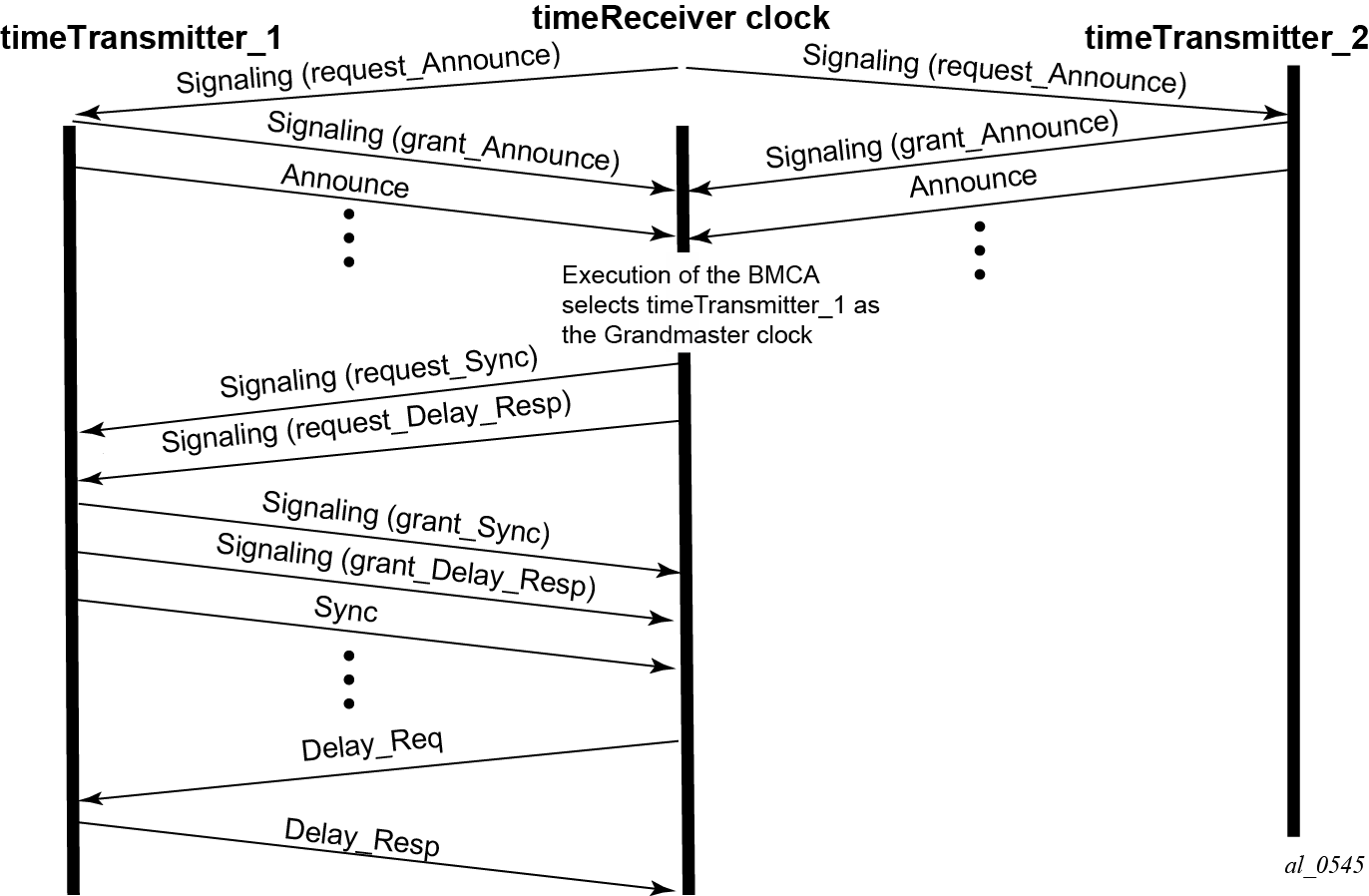
A timeReceiver clock initiates unicast discovery by sending a Signaling message to one of its configured timeTransmitter clocks requesting the timeTransmitter send unicast Announce messages to the timeReceiver. The request includes the desired rate for the Announce messages and the duration over which the messages should be sent. If the timeTransmitter can support the request, it replies with a Signaling message indicating that the session for unicast Announce messages has been granted.
From this point on, the timeTransmitter sends unicast Announce messages to the timeReceiver at the rate requested. A timeReceiver will generally establish an Announce message session with at least two timeTransmitter clocks.
The timeReceiver then uses the Announce messages it receives from all timeTransmitters as input to the BMCA that determines which timeTransmitter clock is the best source for information. The selected timeTransmitter becomes the grandmaster clock to the timeReceiver. The timeReceiver then sends additional Signaling messages to the grandmaster to request unicast delivery of Sync and Delay_Resp messages. Assuming the grandmaster clock has sufficient resources, the request is granted and unicast Sync and Delay_Resp messages are sent from the grandmaster to the timeReceiver.
As with the Announce messages, the rate at which the Sync and Delay_Resp messages are sent and the duration of the unicast sessions is requested by the timeReceiver in the initial Signaling messages.
The unicast sessions for Announce, Sync, and Delay Response messages have an expiry time. The timeReceiver renews all three sessions before this time is reached.
Network Limits
A common concern around IEEE 1588 is whether it will work on or over a specific customer network. For time distribution using full OPS as shown in IEEE 1588 Topology for Time Distribution, there are well defined limits on the number of network elements allowed in the distribution chain (see below). However, for the frequency distribution using the architecture shown in IEEE 1588 Topology for Frequency Distribution, it is a more difficult question to answer. There are so many different types of network elements and inter-node links that a simple limit on the number of network elements is not adequate. What has been specified is a limit to the noise that the network can introduce to the IEEE 1588 message flow between the grandmaster and timeReceiver clocks. This noise occurs as packet delay variation (PDV). The following sections provide some description of this PDV and a new metric that has been defined for PDV as well as the recommended limit to PDV for IEEE 1588 deployments.
Packet Delay Variation
If the packet delay through the packet network is constant, then it is relatively easy to use a series of timestamp exchanges to remove the delay as an unknown and track the timeTransmitter clock frequency. However, in most network technologies, the packet delay will be different for each individual packet. This PDV makes it more difficult to track the timeTransmitter clock because observations have both the timeTransmitter information and PDV noise included.
PDV is introduced when packets get placed in queues before they are forwarded. The time each packet sits in any one queue is influenced by multiple factors:
the speed of the interface toward which the queue drains, for example 100Mbps versus 100Gbps
the traffic load on the interface, for example 20% versus 100% of line capacity
the distribution of packet sizes and priorities in the traffic load toward the interface and
the underlying physical technology used, xPON, xDSL, Ethernet, or microwave
In addition, the load and packet distribution within the load will vary over time so the distribution of the PDV can shift rapidly such as when a network event triggers congestion or slowly, for example, as end customers gradually come online over a period of several hours.
Also, there are pipeline effects that can occur in a chain of queuing devices, where the small timing packets can catch up to a large packets moving across the network. Once behind such a packet, the timing packet can remain stuck behind that packet on all subsequent transmit queues.
QoS prioritization of packets helps reduce PDV significantly during congestion periods, but does not remove the PDV effects during lighter loading. This is due to the fact that a timing packet may be delivered to the egress queue for an interface while the interface is busy transmitting a packet. Pre-emption of packet transmissions is not used in today’s networks.
Having stated all of the above, most of the time, the network will still present a percentage of packets that get across the network with minimal queuing delays. These are often referred to as ‛lucky’ or ‛fastest’ packets. Because these lucky packets are never waiting in queues or have minimal wait times, their transit across the network is relatively consistent. By running a selection filter on all IEEE 1588 packets to find these lucky packets, a level of variation of network delay can be removed or reduced significantly. Then the timeReceiver clocks have a much easier time determining the frequency of the grandmaster.
However, there will always be a limit to the amount of PDV that can be tolerated. The ITU has defined a metric to quantify the PDV, the limit of the PDV for a compliant network, and the required tolerance of a timeReceiver clock.
PDV Metrics
In order to know whether a particular timing-over-packet implementation will meet the performance targets in a given network deployment, it is desirable to both characterize the limits on the PDV that the implementation can tolerate and to measure the network against these limits. In 2012, the ITU-T published three documents that address these requirements:
G.8260 defines the Floor Packet Percentage (FPP) metric.
G.8261.1 defines a network limit for PDV in terms of FPP.
G.8263 defines the input tolerance expected of a IEEE 1588 frequency timeReceiver in terms of FPP.
The Floor Packet Percentage (FPP) metric provides an indication of the guarantee that there are packets experiencing minimal delay across the network. The rationale behind this focus on ‛fastest’ packets is that many networks do provide good consistency of these packets in most operating conditions and because most timeReceiver clocks are capable of operating using only the information from these fastest packets.
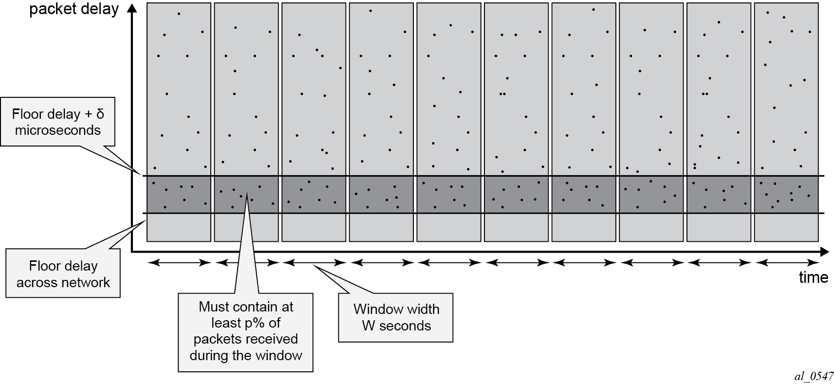
There are four parameters associated with the metric:
W is the width of the windows used to monitor for the presence of fastest packets.
Floor Delay is a value that is as close as possible to the absolute minimum transit delay across the network. Every actual delay measurement must be equal to or larger than this value.
δ is the range above the floor to be analyzed for the presence of fastest packets.
ρ is the percentage of all the packets received in a window whose delay must be within the range floor delay to floor delay + δ.
Floor Packet Counting for FPP (n, W, δ) illustrates how these parameters and the metric work. First the delays of all individual IEEE 1588 packets are plotted over the period of observation. Next, the observation period is broken down into a series of consecutive windows of width W seconds. Then for each window a count is made of all the IEEE 1588 packets whose delays are within the range floor delay to floor delay + δ and this count is compared with all the IEEE 1588 packets received during the window to turn the count into a percentage. Finally, the percentage of each window is checked against the threshold percentage ρ. For the FPP metric to be met, every window must have a percentage greater or equal to the threshold. If even one single window does not meet this threshold then the metric condition is not met.
This metric is not perfect because it does not take into account timeReceivers that use other aspects of the packet delay distribution (such as average delay), nor does it discuss the impact of reroutes, nor do the limits discuss how to apply these limits to the forward and backward message exchanges at the same time. However, it was agreed that this metric was a good start for the definitions of the network and timeReceiver limits. Expect to see timing test equipment vendors providing the tools to generate IEEE 1588 PDV profiles providing FPP based distributions.
ITU-T Budget for Frequency
The network limit on PDV for frequency distribution is defined in G.8271.1 using the FPP metrics defined above.
In general most carrier grade networks with spans of up to 10 nodes and which do not exceed 80% load on their internode links should meet the requirement. However, very low (sub 50 Mbps) shaping or very long networks or last mile technologies such as xDSL or xPON may need to be studied to determine their acceptability.
A general strategy for rolling out IEEE 1588 frequency distribution is to evaluate the specific grandmaster and timeReceiver pairing in a lab environment using a network emulator to introduce controlled PDV. Once the grandmaster and timeReceiver have passed the lab tests, then field trial locations should be identified. Ideally, the sites should include locations where the PDV of the network will likely be at its worst. This would be sites with the most intervening network elements between the grandmasters and the timeReceivers and include segments of the network that have a high load. The timeReceivers’ clocks should be deployed and monitored over several days to ensure that their frequency recovery engines can maintain lock with the grandmasters. During the initial field trails, it is beneficial to use external frequency test equipment at the timeReceiver locations to accurately monitor the frequency generated out of the timeReceivers and ensure it stays within limits. As more sites are evaluated and confidence in the PDV environment increases, more deployments can be rolled out. In the deployed network, PTP frequency recovery timeReceiver states can be monitored to ensure the solution continues to work.
There may be some locations in the network where the PDV will be too large preventing the timeReceivers to achieve or maintain lock. If it is possible to utilize an alternate network interface to obtain a frequency such as a leased T1 or E1 interface then that could be used. A last resort would be the deployment of a GNSS receiver at the location to provide the frequency reference.
ITU-T Budget for Time
The ITU-T has defined a topology for time distribution based on a full OPS environment. This means that every network element in the time distribution chain is an IEEE 1588 clock of some type. Currently the work has defined an environment using Boundary Clocks, but this might be modified in the future to include transparent clocks. The ITU-T tackled the time distribution problem in a more traditional way when compared with the frequency distribution. The ITU-T first defined specific network element clock performance constraints and then defined a longest chain network permitted to ensure that the solution meets the end to end budget. The breakdown of the chain and the budget is shown in G.8271.1 Time Error Budget.
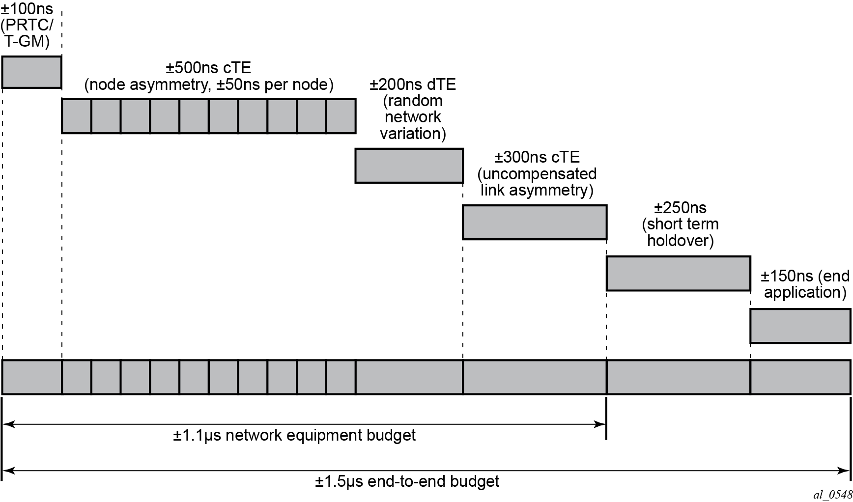
The overall end to end budget is defined as ±1.5 microseconds. From this the following allocations are made:
±100ns Time error due to the GNSS receiver and the IEEE 1588 grandmaster.
±500ns Constant Time error due to ten Telecom Boundary Clocks (50 ns limit per
boundary clock).
±200ns Dynamic Time error presented at the end of the boundary clock chain into the
end timeReceiver.
±300ns Time error due to errors in cable latency asymmetry compensation (see below).
±150ns Time error due to the end timeReceiver and any internals of the base station between
the recovery and the presentation on the air interface.
±200ns Time error in the end application during short term holdovers such as
network topology re-arrangements.
There is discussion that some of these elements could be traded-off against each other. For example, if the link asymmetry needs a higher budget then the holdover budget would have to be less – implying a better end device or a shorter duration of holdover.
The link asymmetries are an important aspect of this budget. The network topology not only has to have the network elements that meet the clock specifications but it also needs to have links that meet certain requirements. As explained above, the time offset calculation makes the assumptions that the timeTransmitter-to-timeReceiver latency is the same from the timeReceiver-to-timeTransmitter latency. When the latency is not equal, an error is introduced. Some analysis of network intersite connections may need to be performed to determine the budget for the link asymmetries.
Configuration
IP Addressing for PTP Communication
The system supports communication to the PTP process on the CPM using any of the IPv4 local interface addresses or an IPv4 local loopback addresses. The system will record both the source and destination address information from the received Signaling message which establishes the unicast session. The system will then swap these addresses for use for the Sync and/or Delay_Req messages generated toward the external clock.
The IP address becomes more significant when IEEE 1588 port based timestamping is enabled. The port level functionality will filter received PTP packets for a known IP address. This ensures that only PTP messages intended for the node are modified and not PTP messages merely transiting the node.
If the IEEE 1588 nodes are directly connected or it is ensured that the PTP messages for a peer shall always enter/exit the system through a single interface, then the IP address of that interface can be used for the PTP message communication. If the PTP messages from a peer could enter through more than one interface, then it may be easier to utilize a loopback address for the PTP message communication.
If using a loopback address and IEEE 1588 port based timestamping is also to be used, then the specific loopback address must be assigned to PTP for use using the source-address command. An example is provided in the ‟Port Based Timestamping” section below.
When a source address is defined for the PTP process within a given routing context, then the source address for all Signaling messages originating out of the node within that routing context shall use that address.
The procedures to establish IP connectivity for the specific addresses used in these examples are not included.
TimeTransmitter and TimeReceiver Clocks for Frequency
A typical deployment scenario for a system configured as an ordinary timeTransmitter to distribute frequency to an external timeReceiver clock, often a cell site router or a base station, is shown in TimeTransmitter and TimeReceiver Clocks for Frequency. The central clock of the system is locked via its BITS ports or a Synchronous Ethernet port to an external source that is traceable to a primary reference. The frequency of the central clock is used to generate the timestamps contained in PTP event messages. The timestamps generated do not correlate to any standard epoch and therefore indicate an arbitrary timescale. As such, it is only the rate of progression of the timestamps that has meaning.
The 7750 SR and the 7450 ESS can be configured as an IEEE 1588 timeReceiver clock for frequency recovery. In real deployments, it is more likely for the timeReceiver devices to be smaller cell site routers or base stations instead of another 7750 SR or 7450 ESS.
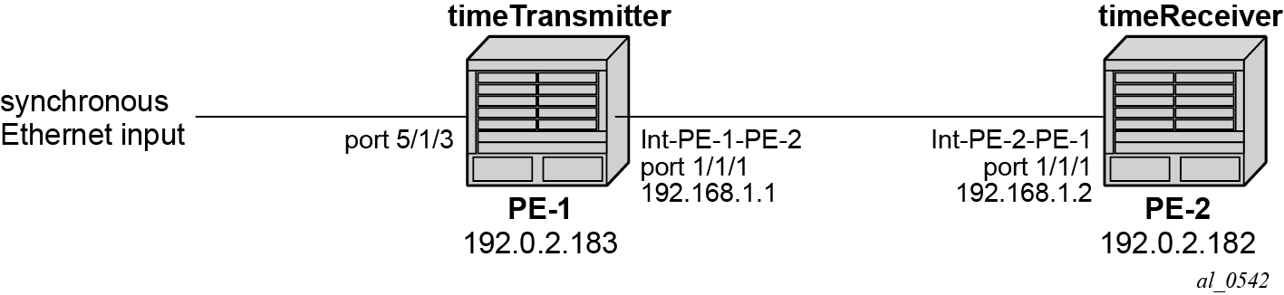
In the topology in TimeTransmitter and TimeReceiver Clocks for Frequency, the systems will most likely be configured with the ITU-T G.8265.1 Profile.
For this example, a loopback address is used for PTP communication between the nodes.
Ordinary timeTransmitter configuration
The steps to configure PE-1 as a PTP ordinary-clock timeTransmitter for frequency distribution using the G.8265.1 Telecom profile are outlined below:
Configure a /32 IPv4 system address on PE-1 and an interface to reach PE-2.
*A:PE-1#
        configure
            router
                interface "system"
                    address 192.0.2.183/32
                    no shutdown
                exit
                interface "int-PE-1-PE-2"
                    address 192.168.1.1/30
                    port 1/1/1
                    no shutdown
                exit
            exit
Configure an input reference for the central clock on PE-1. In this example, Synchronous Ethernet port 5/1/3 is used as the source for ref2.
*A:PE-1#
        configure
            port 5/1/3
                description "Sync-E reference for node"
                ethernet
                    ssm
                        code-type sonet
                        no shutdown
                    exit
                exit
                no shutdown
            exit
            system
                sync-if-timing
                    begin
                    ql-selection
                    ref2
                        source-port 5/1/3
                        no shutdown
                    exit
                    commit
                exit
            exit
The default clock-type is set to ordinary slave so that must be changed to ordinary master. The only other relevant configuration parameter for the timeTransmitter clock running the G.8265.1 profile is the network-type. The coding of the SSM/ESMC Quality Level into PTP clock Class must match the environment. The system supports both SONET and SDH networks. The default network-type is sdh but for this example, the system is configured for the North American market so the network-type is set to sonet.
*A:PE-1#
        configure
            system
                ptp
                    clock-type ordinary master
                    network-type sonet
                    no shutdown
                exit
            exit
Ordinary timeReceiver configuration
To configure PE-2 as a PTP ordinary timeReceiver for frequency distribution using the G.8265.1 Telecom profile, firstly configure a /32 IPv4 system address on PE-2 and an interface to reach PE-1.
*A:PE-2#
        configure
            router
                interface "system"
                    address 192.0.2.182/32
                    no shutdown
                exit
                interface "int-PE-2-PE-1"
                    address 192.168.1.2/30
                    port 1/1/1
                    no shutdown
                exit
            exit
As the default clock-type is ordinary slave, PE-1 is configured as a peer clock, and the PTP process is enabled. In this example, the Quality Level encoding is also changed to sonet in order to match the North American market
*A:PE-1#
        configure
            system
                ptp
                    network-type sonet
                    peer 192.0.2.183 create
                        no shutdown
                    exit
                    no shutdown
                exit
            exit
Usually, an IEEE 1588 timeReceiver has at least two peers configured in order to provide redundant sources.
Configure PTP as the reference for the central clock on PE-2.
*A:PE-2#
        configure
            system
                sync-if-timing
                    begin
                    ql-selection
                    ptp
                        no shutdown
                    exit
                    commit
                exit
            exit
Verification of Session Establishment
When PTP is set to no shutdown on PE-2, it initiates a PTP unicast session with PE-1. Correct session establishment can be verified by checking PTP related information as follows:
*A:PE-1# show system ptp unicast
===============================================================================
IEEE 1588/PTP Unicast Negotiation Information
===============================================================================
Router
  IP Address      Dir Type     Rate       Duration State    Time
-------------------------------------------------------------------------------
Base
  192.0.2.182     Tx  Announce 1 pkt/2 s  300      Granted  05/30/2014 06:08:38
  192.0.2.182     Tx  Sync     64 pkt/s   300      Granted  05/30/2014 06:08:43
  192.0.2.182     Rx  DelayReq 64 pkt/s   300      Granted  05/30/2014 06:08:43
  192.0.2.182     Tx  DelayRsp 64 pkt/s   300      Granted  05/30/2014 06:08:43
-------------------------------------------------------------------------------
PTP Peers               : 1
Total Packet Rate       : 192 packets/second
===============================================================================

*A:PE-2# show system ptp unicast
===============================================================================
IEEE 1588/PTP Unicast Negotiation Information
===============================================================================
Router
  IP Address      Dir Type     Rate       Duration State    Time
-------------------------------------------------------------------------------
Base
  192.0.2.183     Rx  Announce 1 pkt/2 s  300      Granted  05/30/2014 09:08:38
  192.0.2.183     Rx  Sync     64 pkt/s   300      Granted  05/30/2014 09:08:43
  192.0.2.183     Tx  DelayReq 64 pkt/s   300      Granted  05/30/2014 09:08:43
  192.0.2.183     Rx  DelayRsp 64 pkt/s   300      Granted  05/30/2014 09:08:43
-------------------------------------------------------------------------------
PTP Peers               : 1
Total Packet Rate       : 192 packets/second
===============================================================================
A Pending state indicates the system has sent a Unicast Request toward the peer but has not received a response. If the state remains Pending, then the IP connectivity between the systems should be verified.
To verify the timeReceiver frequency is operating properly, first check the high level information for PTP on PE-2.
The PTP Recovery State initially shows phase-tracking and then changes to locked. The time to achieve locked state varies based on the PDV.
*A:PE-2# show system ptp
===============================================================================
IEEE 1588/PTP Clock Information
===============================================================================
-------------------------------------------------------------------------------
Local Clock
-------------------------------------------------------------------------------
Clock Type        : ordinary,slave     PTP Profile        : ITU-T G.8265.1
Domain            : 4                  Network Type       : sonet
Admin State       : up                 Oper State         : up
Announce Interval : 1 pkt/2 s          Announce Rx Timeout: 3 intervals
Peer Limit        : none (Base Router)
Clock Id          : 00233efffe808250   Clock Class        : 255 (slave-only)
Clock Accuracy    : unknown            Clock Variance     : ffff (not computed)
Clock Priority1   : 128                Clock Priority2    : 128
PTP Port State    : slave              Last Changed       : 05/30/2014 09:08:42
PTP Recovery State: phase-tracking     Last Changed       : 05/30/2014 09:08:42
Frequency Offset  : -2.704 ppb
-------------------------------------------------------------------------------
Parent Clock
-------------------------------------------------------------------------------
IP Address        : 192.0.2.183        Router             : Base
Parent Clock Id   : 00233efffe69f250   Remote PTP Port    : 1
GM Clock Id       : 00233efffe69f250   GM Clock Class     : 80 (prs)
GM Clock Accuracy : unknown            GM Clock Variance  : ffff (not computed)
GM Clock Priority1: 128                GM Clock Priority2 : 128
-------------------------------------------------------------------------------
Time Information
-------------------------------------------------------------------------------
Timescale           : Arbitrary
Current Time        : 2014/05/30 14:12:52.9 (ARB)
Frequency Traceable : yes
Time Traceable      : no
Time Source         : other
===============================================================================
In addition, PTP packet statistics can be checked to verify reception of the PTP messages and the execution of the frequency timeReceiver:
*A:PE-2# show system ptp statistics
===============================================================================
IEEE 1588/PTP Packet Statistics
===============================================================================
                                                               Input     Output
-------------------------------------------------------------------------------
PTP Packets                                                     5506       2742
  Announce                                                        23          0
  Sync                                                          2740          0
  Follow Up                                                        0          0
  Delay Request                                                    0       2740
  Delay Response                                                2740          0
  Signaling                                                        3          3
    Request Unicast Transmission TLVs                              0          3
      Announce                                                     0          1
      Sync                                                         0          1
      Delay Response                                               0          1
    Grant Unicast Transmission (Accepted) TLVs                     3          0
      Announce                                                     1          0
      Sync                                                         1          0
      Delay Response                                               1          0
    Grant Unicast Transmission (Denied) TLVs                       0          0
      Announce                                                     0          0
      Sync                                                         0          0
      Delay Response                                               0          0
    Cancel Unicast Transmission TLVs                               0          0
      Announce                                                     0          0
      Sync                                                         0          0
      Delay Response                                               0          0
    Ack Cancel Unicast Transmission TLVs                           0          0
      Announce                                                     0          0
      Sync                                                         0          0
      Delay Response                                               0          0
    Other TLVs                                                     0          0
  Other                                                            0          0
  Event Packets timestamped at port                                0          0
  Event Packets timestamped at cpm                              2740       2740
Discards                                                           0          0
  Bad PTP domain                                                   0          0
  Alternate Master                                                 0          0
  Out Of Sequence                                                  0          0
  Peer Disabled                                                    0          0
  Other                                                            0          0
===============================================================================
===============================================================================
IEEE 1588/PTP Frequency Recovery State Statistics
===============================================================================
State                                                                   Seconds
-------------------------------------------------------------------------------
Initial                                                                       0
Acquiring                                                                     0
Phase-Tracking                                                               43
Locked                                                                        0
Hold-over                                                                     0
===============================================================================

===============================================================================
IEEE 1588/PTP Event Statistics
===============================================================================
Event                                                      Sync Flow Delay Flow
-------------------------------------------------------------------------------
Packet Loss                                                        0          0
Excessive Packet Loss                                              0          0
Excessive Phase Shift Detected                                     0          0
Too Much Packet Delay Variation                                    0          0
===============================================================================
*
Secondly, the central clock status on the system can be checked:
*A:PE-2# show system sync-if-timing
===============================================================================
System Interface Timing Operational Info
===============================================================================
System Status CPM B                : Master Locked
    Reference Input Mode           : Non-revertive
    Quality Level Selection        : Disabled
    Reference Selected             : ptp
    System Quality Level           : prs
    Current Frequency Offset (ppm) : +0

Reference Order                    : bits ref1 ref2 ptp

Reference Mate CPM
    Qualified For Use              : No
        Not Qualified Due To       :     LOS
    Selected For Use               : No
        Not Selected Due To        :     not qualified

Reference Input 1
    Admin Status                   : down
    Rx Quality Level               : unknown
    Quality Level Override         : none
    Qualified For Use              : No
        Not Qualified Due To       :     disabled
    Selected For Use               : No
        Not Selected Due To        :     disabled
    Source Port                    : None

Reference Input 2
    Admin Status                   : down
    Rx Quality Level               : unknown
    Quality Level Override         : none
    Qualified For Use              : No
        Not Qualified Due To       :     disabled
    Selected For Use               : No
        Not Selected Due To        :     disabled
    Source Port                    : None

Reference BITS B
    Input Admin Status             : down
    Rx Quality Level               : failed
    Quality Level Override         : none
    Qualified For Use              : No
        Not Qualified Due To       :     disabled
    Selected For Use               : No
        Not Selected Due To        :     disabled
    Interface Type                 : DS1
    Framing                        : ESF
    Line Coding                    : B8ZS
    Line Length                    : 0-110ft
    Output Admin Status            : down
    Output Source                  : line reference
    Output Reference Selected      : none
    Tx Quality Level               : N/A

Reference PTP
    Admin Status                   : up
    Rx Quality Level               : prs
    Quality Level Override         : none
    Qualified For Use              : Yes
    Selected For Use               : Yes
Optional configuration items for ordinary timeTransmitter or timeReceiver configuration
The G.8265.1 profile is the default PTP profile on the system and it uses domain number value of 4. The domain number must match at both ends of the communication path or the PTP messages will be dropped. Some very old IEEE 1588 devices, may have the domain number set to zero, which is the value used by the IEEE 1588 default profile. In this case, the system would need to have its domain number changed to match that of the external timeReceiver.
        configure
            system
                ptp
                    shutdown
                    domain 0
                    no shutdown
                exit
            exit
The domain number can only be adjusted if PTP is shutdown and only one common domain number is allowed for all IEEE 1588 messages to and from the system.
When using the system as an IEEE 1588 timeReceiver for frequency distribution, it is strongly recommended to use the default message rate of 64 pps for Sync and Delay_Resp messages. If for some reason the parent IEEE 1588 peer cannot offer this rate, then the rate that the system requests must be adjusted. For example, if the maximum rate supported by the external IEEE 1588 grandmaster device (with an IP address of 192.0.2.166) only is 32 pps, then the system can be adjusted to request that rate as follows:
        configure
            system
                ptp
                    peer 192.0.2.166 create
                        log-sync-interval -5
                        no shutdown
                    exit
                exit
            exit
The Sync message rate can only be adjusted if the peer is shutdown.
The message rates are entered as the base 2 logarithm of the inter-message interval. So 32 pps has an inter message interval of 1/32 seconds and a log-sync-interval of -5.
The Announce message rate impacts the speed at which PTP can detect communication failures and the speed at which the PTP topology is re-arranged. The default Announce rate is one message every two seconds and this should be adequate for networks with short chains of PTP clocks, for example, G.8265.1 architectures. However, in network with longer chains of PTP clocks (for example, more than 5 boundary clocks), it may be desired to use a faster Announce message rate. In the following example, the timeReceiver is configured to request two Announce messages per second:
        configure
            system
                ptp
                    shutdown
                    log-anno-interval -1
                    no shutdown
                exit
            exit
The Announce rate can only be adjusted if PTP is shutdown. In addition, there is one common Announce rate for all unicast sessions; it cannot be configured on an individual peer basis.
Boundary Clock
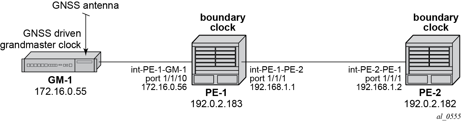
With the increase interest in high accuracy time distribution across networks, the system most likely takes on the role of an IEEE 1588 boundary clock. In this role, the system requests time from a GNSS driven grandmaster clock or from a neighboring boundary clock. The system only supports boundary clock configuration when the ptp profile is configured as the default profile.
In this mode of operation, it is strongly recommended to have Synchronous Ethernet physical layer frequency distribution configured at the same time.
The example in Boundary Clock shows a boundary clock (PE-1) communicating directly with the GNSS driven grandmaster (GM-1) and a second boundary clock (PE-2) communicating with the first boundary clock.
The steps to configure the systems as boundary clocks running the IEEE default profile are:
On PE-1, configure a /32 IPv4 system address, an interface to reach PE-2, and an interface to reach GM-1.
*A:PE-1#
        configure
            router
                interface "system"
                    address 192.0.2.183/32
                    no shutdown
                exit
                interface "int-PE-1-PE-2"
                    address 192.168.1.1/30
                    port 1/1/1
                    no shutdown
                exit
                interface "int-PE-1-GM-1"
                    address 172.16.0.56/30
                    port 1/1/2
                    no shutdown
                exit
            exit
On PE-2, configure a /32 IPv4 system address and an interface to reach PE-1.
*A:PE-2#
        configure
            router
                interface "system"
                    address 192.0.2.182/32
                    no shutdown
                exit
                interface "int-PE-2-PE-1"
                    address 192.168.1.2/30
                    port 1/1/1
                    no shutdown
                exit
            exit
Configure both PE-1 and PE-2 to have physical layer frequency sources into their central clocks. PE-2 is configured to receive Synchronous Ethernet from PE-1 on the same port as is used for PTP. This commonality is not a requirement but might be common in the network topology.
On PE-1, configure the port toward PE-2 as a Synchronous Ethernet port. This will cause the port transmit timing to be sourced from the node timing. Also, configure the port to transmit ssm codes using the sonet codes.
*A:PE-1#
        configure card 1 mda 1 sync-e
        configure port 1/1/1 ethernet
            code-type sonet
            no shutdown
        exit
On PE-2, configure the port on toward PE-1 as a Synchronous Ethernet port and to use sonet codes and to be the reference into the central clock of PE-2.
*A:PE-2#
        configure card 1 mda 1 sync-e
        configure port 1/1/1
            ethernet
                ssm
                    code-type sonet
                    no shutdown
                exit
            exit
        exit
        configure system sync-it-timing
            begin
            ql-selection
            ref1
                source-port 1/1/1
                no shutdown
            exit
            commit
        exit
Next, configure PE-1 as a boundary clock requesting service from GM-1 using the default profile. In this example, the interface address of GM-1 is used for the PTP communication.
*A:PE-1#
        configure system ptp
            shutdown
            profile ieee1588-2008
            clock-type boundary
            peer 172.16.0.55 create
                no shutdown
            exit
            no shutdown
        exit
If it is desired to operate the network at the default for the G.8275.1 profile, then the Announce messages should be set to 8 pps and the Sync and Delay_Resp messages should be set to 16 pps.
*A:PE-1#
        configure system ptp
            shutdown
            log-anno-interval -3
            peer 172.16.0.55
                shutdown
                log-sync-interval -4
                no shutdown
            exit
            no shutdown
        exit
Configure PE-2 as a boundary clock using PE-1 as its parent clock and the same set of IEEE 1588 parameters. In this example, PE-2 uses a loopback address of PE-1 for communication.
*A:PE-2#
        configure system ptp
            shutdown
            profile ieee1588-2008
            clock-type boundary
            log-anno-interval -3
            peer 192.0.2.183 create
                shutdown
                log-sync-interval -4
                no shutdown
            exit
            no shutdown
        exit
On PE-1, validate the status of the PTP topology by checking the unicast sessions. Also validate the PTP process has elected GM-1 as both the parentClock and the grandmaster clock.
*A:PE-1# show system ptp unicast
===============================================================================
IEEE 1588/PTP Unicast Negotiation Information
===============================================================================
Router
  IP Address      Dir Type     Rate       Duration State    Time
-------------------------------------------------------------------------------
Base
  192.0.2.182     Tx  Announce 8 pkt/s    300      Granted  05/30/2014 07:02:36
  192.0.2.182     Tx  Sync     16 pkt/s   300      Granted  05/30/2014 07:02:37
  192.0.2.182     Rx  DelayReq 16 pkt/s   300      Granted  05/30/2014 07:02:37
  192.0.2.182     Tx  DelayRsp 16 pkt/s   300      Granted  05/30/2014 07:02:37
  172.16.0.55     Rx  Announce 8 pkt/s    300      Granted  05/30/2014 07:02:42
  172.16.0.55     Rx  Sync     16 pkt/s   300      Granted  05/30/2014 07:02:43
  172.16.0.55     Tx  DelayReq 16 pkt/s   300      Granted  05/30/2014 07:02:43
  172.16.0.55     Rx  DelayRsp 16 pkt/s   300      Granted  05/30/2014 07:02:43
-------------------------------------------------------------------------------
PTP Peers               : 2
Total Packet Rate       : 112 packets/second
===============================================================================

*A:PE-1# show system ptp
===============================================================================
IEEE 1588/PTP Clock Information
===============================================================================
-------------------------------------------------------------------------------
Local Clock
-------------------------------------------------------------------------------
Clock Type        : boundary           PTP Profile        : IEEE 1588-2008
Domain            : 0                  Network Type       : sdh
Admin State       : up                 Oper State         : up
Announce Interval : 8 pkt/s            Announce Rx Timeout: 3 intervals
Peer Limit        : none (Base Router)
Clock Id          : 00233efffe69f250   Clock Class        : 248 (default)
Clock Accuracy    : unknown            Clock Variance     : ffff (not computed)
Clock Priority1   : 128                Clock Priority2    : 128
PTP Recovery State: locked             Last Changed       : 05/30/2014 07:05:17
Frequency Offset  : +50.305 ppb
-------------------------------------------------------------------------------
Parent Clock
-------------------------------------------------------------------------------
IP Address        : 172.16.0.55        Router             : Base
Parent Clock Id   : 8887868584838281   Remote PTP Port    : 1
GM Clock Id       : 8887868584838281   GM Clock Class     : 7
GM Clock Accuracy : within 250 ns      GM Clock Variance  : 0x6400 (3.7E-09)
GM Clock Priority1: 128                GM Clock Priority2 : 128
-------------------------------------------------------------------------------
Time Information
-------------------------------------------------------------------------------
Timescale           : PTP
Current Time        : 2014/05/30 15:07:01.1 (UTC)
Frequency Traceable : yes
Time Traceable      : yes
Time Source         : GPS
On PE-2, validate the PTP process has elected PE-1 as its parentClock and that the grandmaster clock is GM-1.
*A:PE-2# show system ptp
===============================================================================
IEEE 1588/PTP Clock Information
===============================================================================
-------------------------------------------------------------------------------
Local Clock
-------------------------------------------------------------------------------
Clock Type        : boundary           PTP Profile        : IEEE 1588-2008
Domain            : 0                  Network Type       : sdh
Admin State       : up                 Oper State         : up
Announce Interval : 8 pkt/s            Announce Rx Timeout: 3 intervals
Peer Limit        : none (Base Router)
Clock Id          : 00233efffe808250   Clock Class        : 248 (default)
Clock Accuracy    : unknown            Clock Variance     : ffff (not computed)
Clock Priority1   : 128                Clock Priority2    : 128
PTP Recovery State: locked             Last Changed       : 05/30/2014 10:02:36
Frequency Offset  : -9.345 ppb
-------------------------------------------------------------------------------
Parent Clock
-------------------------------------------------------------------------------
IP Address        : 192.0.2.183        Router             : Base
Parent Clock Id   : 00233efffe69f250   Remote PTP Port    : 1
GM Clock Id       : 8887868584838281   GM Clock Class     : 7
GM Clock Accuracy : within 250 ns      GM Clock Variance  : 0x6400 (3.7E-09)
GM Clock Priority1: 128                GM Clock Priority2 : 128
-------------------------------------------------------------------------------
Time Information
-------------------------------------------------------------------------------
Timescale           : PTP
Current Time        : 2014/05/30 15:09:26.5 (UTC)
Frequency Traceable : yes
Time Traceable      : yes
Time Source         : GPS
===============================================================================
Boundary Clock with VPRN Access
The system supports access to the IEEE 1588 process through Base routing, ies, and vprn contexts. This permits the system IEEE 1588 topology to be created and managed in one context with access for edge distribution through other contexts. For example, building on top of the base routing distribution shown in the previous example, access can be given to the IEEE 1588 process on PE-2 via a VPRN existing on that node. This allows the VPRN customer to have access to the high accuracy time available within the system in the customer edge equipment connecting into that node.
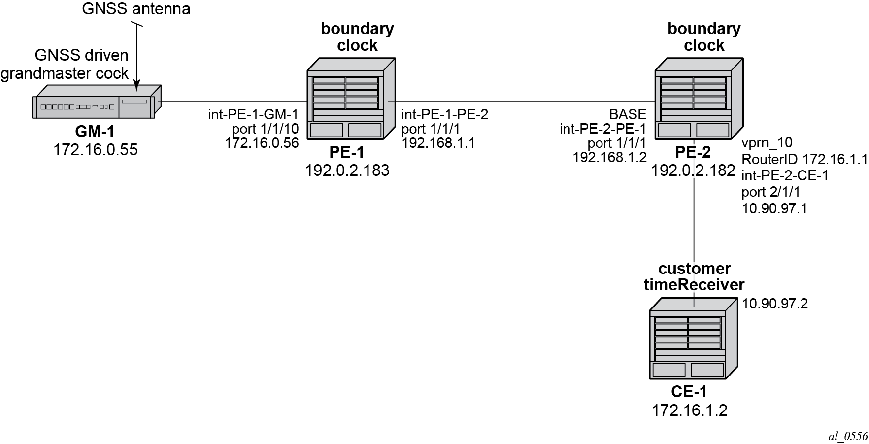
For the example shown in Boundary Clocks with Edge VPRN Access, it is assumed that a VPRN service is already configured and operational on PE-2 providing connectivity between PE-2 and CE-1:
*A:PE-2#
        configure service vprn 10 customer 1 create
            router-id 176.16.1.1
            autonomous-system 64496
            route-distinguisher 64496:10
            interface "int-PE-2-CE-1" create
                address 10.90.97.1/30
                sap 2/1/1 create
                exit
            exit
            no shutdown
        exit
To enable access to the PTP process via VPRN 10 in PE-2, PTP must be enabled within the vprn context. To ensure that no more than 10 external clocks access the system PTP through this VPRN at any one time, a peer-limit may be defined.
*A:PE-2#
        configure service vprn 10
            peer-limit 10
            ptp no shutdown
        exit
To confirm PTP access with the VPRN, the PTP information with the vprn context can be queried. Either of the following two commands can be used:
*A:PE-2# show system ptp unicast router 10
or
*A:PE-2# show service id 10 ptp unicast
These two commands provide the same information as shown below.
*A:PE-2# show system ptp unicast router 10
===============================================================================
IEEE 1588/PTP Unicast Negotiation Information
===============================================================================
Router
  IP Address      Dir Type     Rate       Duration State    Time
-------------------------------------------------------------------------------
10
  172.16.1.2      Tx  Announce 1 pkt/2 s  300      Granted  05/30/2014 12:40:53
  172.16.1.2      Tx  Sync     64 pkt/s   300      Granted  05/30/2014 12:40:59
  172.16.1.2      Rx  DelayReq 64 pkt/s   300      Granted  05/30/2014 12:40:59
  172.16.1.2      Tx  DelayRsp 64 pkt/s   300      Granted  05/30/2014 12:40:59
-------------------------------------------------------------------------------
PTP Peers               : 1
Total Packet Rate       : 192 packets/second
===============================================================================
Port Based Timestamping
As described above, optimal performance is achieved when the IEEE 1588 port based timestamping (PBT) feature is used. This feature is not available on all hardware and the interfaces for PTP should be planned in advance if this feature is to be used.
Because IEEE 1588 messages ingress and egress the node through router interfaces, the configuration of the IEEE 1588 PBT feature is enabled within the router interface context. In the previous examples, if IEEE 1588 PBT is to be enabled on all the PTP interfaces the following commands are required.
On PE-1, enable IEEE 1588 PBT on the interface toward GM-1 and PE-2.
*A:PE-1#
        configure
            router
                interface "int-PE-1-PE-2"
                    ptp-hw-assist
                exit
                interface "int-PE-1-GM-1"
                    ptp-hw-assist
                exit
            exit
On PE-2, enable IEEE 1588 PBT on the interface toward PE-1 and CE-1.
*A:PE-2#
        configure
            router
                interface "int-PE-2-PE-1"
                    ptp-hw-assist
                exit
            exit
        exit
        configure service vprn 10 customer 1
            interface "int-PE-2-CE-1"
                ptp-hw-assist
            exit
        exit
To verify IEEE 1588 PBT is active on the IEEE 1588 messages to the peers, check the timestamp point for the specific peer. It now indicates port rather than cpm.
On PE-1 for the CE-1 communication:
*A:PE-1# show system ptp peer 172.16.0.55
===============================================================================
IEEE 1588/PTP Peer Information
===============================================================================
Router            : Base
IP Address        : 172.16.0.55        Announce Direction : rx
Admin State       : up                 G.8265.1 Priority  : n/a
Sync Interval     : 16 pkt/s
Local PTP Port    : 2                  PTP Port State     : slave
Clock Id          : 8887868584838281   Remote PTP Port    : 1
GM Clock Id       : 8887868584838281   GM Clock Class     : 7
GM Clock Accuracy : within 250 ns      GM Clock Variance  : 0x6400 (3.7E-09)
GM Clock Priority1: 128                GM Clock Priority2 : 128
Steps Removed     : 0                  Parent Clock       : yes
Tx Timestamp Point: port               Rx Timestamp Point : port
Last Tx Port      : 5/1/1              Last Rx Port       : 5/1/1
===============================================================================
On PE-1 the communication with the PE-2 will still be CPM timestamping because the port has not been configured to watch for the system loopback address.
*A:PE-1# show system ptp peer 192.0.2.182
===============================================================================
IEEE 1588/PTP Peer Information
===============================================================================
Router            : Base
IP Address        : 192.0.2.182        Announce Direction : tx
Admin State       : n/a                G.8265.1 Priority  : n/a
Sync Interval     : n/a
Local PTP Port    : 3                  PTP Port State     : master
Clock Id          : 00233efffe808250   Remote PTP Port    : 4
Tx Timestamp Point: cpm                Rx Timestamp Point : cpm
Last Tx Port      : 5/1/2              Last Rx Port       : 5/1/2
===============================================================================
In order to configure the system loopback address for PTP, enter the following on PE-1:
*A:PE-1#
        configure
            system security
                source-address application ptp "system"
                exit
            exit
Now the timestamp point on PE-1 will be the port.
*A:PE-1# show system ptp peer 192.0.2.182
===============================================================================
IEEE 1588/PTP Peer Information
===============================================================================
Router            : Base
IP Address        : 192.0.2.182        Announce Direction : tx
Admin State       : n/a                G.8265.1 Priority  : n/a
Sync Interval     : n/a
Local PTP Port    : 3                  PTP Port State     : master
Clock Id          : 00233efffe808250   Remote PTP Port    : 4
Tx Timestamp Point: port               Rx Timestamp Point : port
Last Tx Port      : 5/1/2              Last Rx Port       : 5/1/2
===============================================================================
Repeat this configuration of system address for the base routing context on PE-2
*A:PE-2#
        configure
            system security
                source-address application ptp "system"
                exit
            exit
Now the timestamp point on PE-2 will be the port.
*A:PE-2# show system ptp peer 192.0.2.183
===============================================================================
IEEE 1588/PTP Peer Information
===============================================================================
Router            : Base
IP Address        : 192.0.2.183        Announce Direction : rx
Admin State       : up                 G.8265.1 Priority  : n/a
Sync Interval     : 16 pkt/s
Local PTP Port    : 4                  PTP Port State     : slave
Clock Id          : 00233efffe69f250   Remote PTP Port    : 3
GM Clock Id       : 8887868584838281   GM Clock Class     : 6
GM Clock Accuracy : within 100 ns      GM Clock Variance  : 0x6400 (3.7E-09)
GM Clock Priority1: 128                GM Clock Priority2 : 128
Steps Removed     : 1                  Parent Clock       : yes
Tx Timestamp Point: port               Rx Timestamp Point : port
Last Tx Port      : 1/1/2              Last Rx Port       : 1/1/2
===============================================================================
On PE-2, a loopback address must assigned for PTP communication as follows:
*A:PE-2#
configure service vprn 10
    interface "ptp_loopback"
        address 172.16.1.1/32
        loopback
    exit
    source-address
        application ptp "ptp_loopback"
            exit
        exit
IEEE 1588 as NTP Local Clock (server)
If the system is configured as a boundary clock or timeReceiver clock, then the time recovered from the IEEE 1588 timeReceiver port can be used as the source of system time on the node. This allows for higher accuracy and better stability in the timebase when compared to NTP. To enable this, PTP must be made the preferred server in the ntp context in the node.
If the system is acting as an NTP server or peer to other NTP clocks, then turning on this feature will impact the existing NTP topology. The system shall advertise itself as an NTP Stratum 1 server to external clients and peers. Given the much higher accuracies achievable with PTP time distribution, this change in topology does not degrade the time in the clients and peers.
*A:PE-1#
        configure system time ntp
            server ptp prefer
        exit
To validate PTP is now being used for NTP time and system time, use the following command:
*A:PE-1# show system ntp all
===============================================================================
NTP Status
===============================================================================
Configured         : Yes                Stratum              : 1
Admin Status       : up                 Oper Status          : up
Server Enabled     : No                 Server Authenticate  : No
Clock Source       : ptp
Auth Check         : Yes
Current Date & Time: 2014/05/30 17:53:11 UTC
===============================================================================
===============================================================================
NTP Active Associations
===============================================================================
State                     Reference ID    St Type  A  Poll Reach     Offset(ms)
    Remote
-------------------------------------------------------------------------------
chosen                    PTP             0  srvr  -  64   ......YY  0.000
    ptp
===============================================================================
===============================================================================
NTP Clients
===============================================================================
vRouter                                                    Time Last Request Rx
    Address
-------------------------------------------------------------------------------
===============================================================================
Conclusion
The systems provide support for IEEE 1588 frequency and time distribution for the synchronization applications of the mobile networks. They can be configured as frequency distribution grandmasters and timeReceiver clocks or time distribution boundary and timeReceiver clocks.