QoS Architecture and Basic Operation
This chapter provides information about QoS architecture and basic operation.
Topics in this chapter include:
Applicability
The chapter was initially written for SR OS Release 9.0.R3. The CLI in the current edition corresponds to SR OS Release 14.0.R2.
Overview
The 7x50 platforms provide an extensive Quality of Service (QoS) capability for service provider solutions. QoS is a system behavior to provide different traffic with different amounts of resources, including buffer memory and queue serving time.
By allocating system resources with certain degrees of guarantee, the bandwidth can be used more efficiently and more controllably. Lack of buffer memory leads to packet drop, while a smaller amount of queue serving time normally means longer delay for the packet and may cause buffer memory to be completely consumed and eventually also lead to packet drop.
In a system, such as the 7x50 platform, different types of traffic contend for the same resources at several major points, such as the ingress to the switch fabric and the egress out of a physical port. In a multi-node network, QoS is achieved on hop by hop basis. Thus, QoS needs to be configured individually but with the consistency across the whole network.
This chapter is focused on the configuration of the basic QoS, namely the use of queues to shape traffic at the ingress and egress of the system. More sophisticated aspects will be referenced where appropriate but their details are beyond the scope of this chapter. Other topics not included are Hierarchical QoS scheduling, egress port-scheduler, queue-groups, named buffer pools, WRED-per-queue, LAGs, high scale MDA, QoS for ATM/FR and Enhanced Subscriber Management.
QoS Components
QoS consists of four main components:
Classification
Buffering (enqueuing)
Scheduling (dequeuing)
Remarking
These are also the fundamental building blocks of the QoS implementation in the 7x50. Ingress packets, classified by various rules, belong to one of eight Forwarding Classes (FC). An FC can be viewed a set of packets which are treated in a similar manner within the system (have the same priority level and scheduling behavior). Each FC has a queue associated with it and each queue has a set of parameters controlling how buffer memory is allocated for packets; if a packet is enqueued (placed on the queue) a scheduler will control the way the packet gets dequeued (removed from the queue) relative to other queues. When a packet exits an egress port, a remarking action can be taken to guarantee the next downstream device will properly handle the different types of traffic.
Configuration
Policies
QoS policies are used to control how traffic is handled at distinct points in the service delivery model within the device. There are different types of QoS policies catering to the different QoS needs at each point. QoS policies only take effect when applied to a relevant entity (Service Access Point (SAP) or network port/interface) so by default can be seen as templates with each application instantiating a new set of related resources.
The following QoS policies are discussed:
Ingress/egress QoS Policies — For classification, queue attributes and remarking.
Slope policies — Define the RED slope definitions.
Scheduler policies — Determine how queues are scheduled (only the default scheduling is included here).
Access, Network, and Hybrid Ports
The system has two different types of interfaces: access and network.
A network interface will classify packets received from the network core at ingress and remark packets sent to the core at egress. Aggregated differentiated service QoS is performed on network ports, aggregating traffic from multiple services into a set of queues per FC.
An access interface connects to one or more customer devices; it receives customer packets, classifies them into different FCs at ingress and remarks packets according to FCs at egress. Since an access interface needs application awareness, it has many more rules to classify the ingress packets. Access and network also differ in how buffer memory is handled, as will be made clear when discussing the buffer management. Here the QoS is performed per SAP.
Access interfaces (SAPs) are configured on access ports and network interfaces are configured on network ports. A third type of port is available, the hybrid port, which supports both access and network interfaces on the same port.
Hybrid ports are only supported on Ethernet ports and optionally with a single-chassis LAG. They must be configured to use VLANs (either single (dot1q encapsulation) or double (QinQ encapsulation) tagging) with each VLAN mapping to either the access or network part of the port. This allows the classification to associate incoming traffic with the correct port type and service. Port based traffic, such as LACP, CCM and EFM, uses a system queue on an access port, but the default network queues on a network or hybrid port.
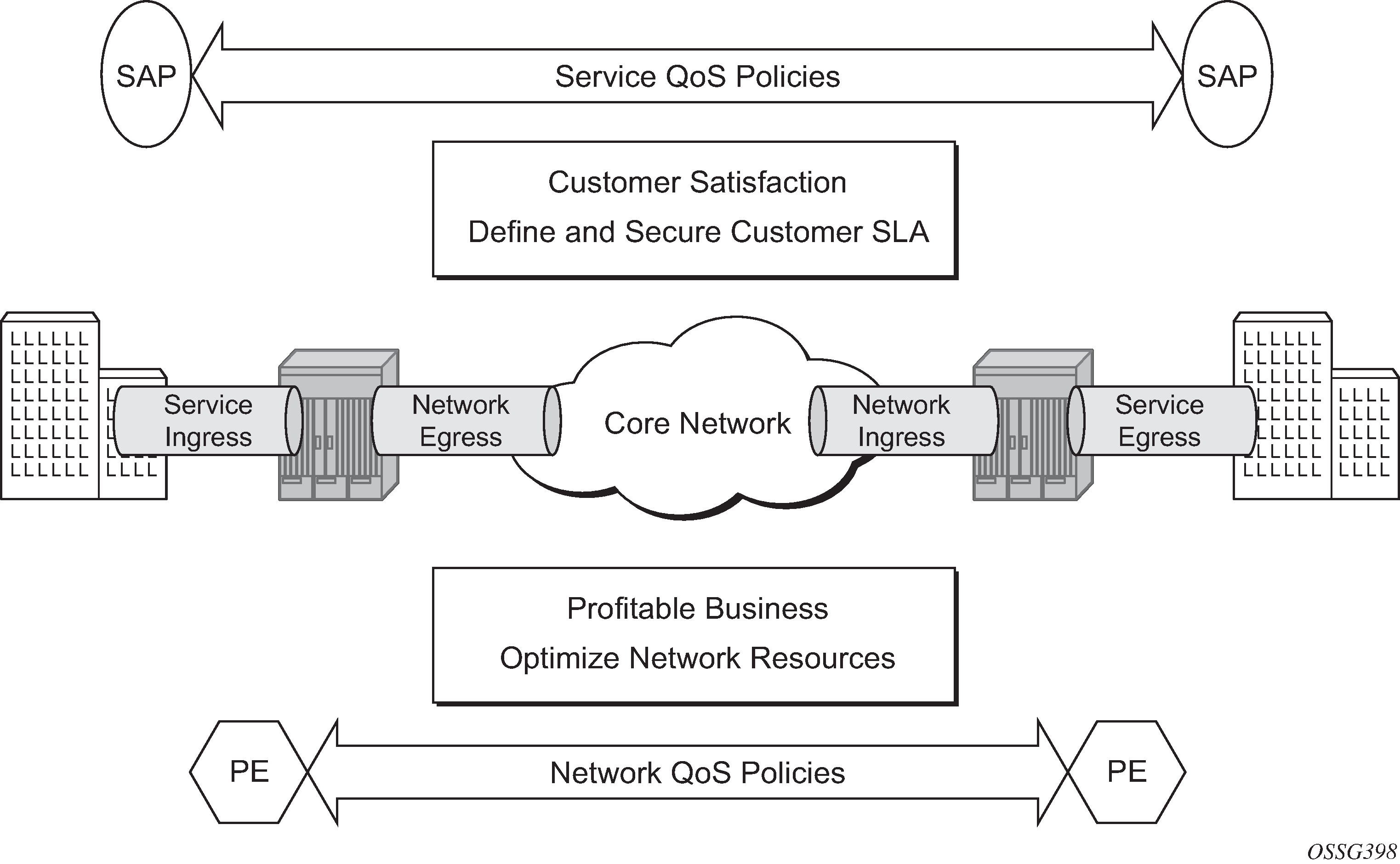
Customer traffic follows the path shown below:
[service ingress → network egress] |
→ |
[network ingress → network egress] |
→ |
[network ingress → service egress] |
ingress PE |
transit P |
egress PE |
The network administrator needs to make sure that QoS is configured correctly at each point using the appropriate QoS policies (Service and Network QoS Policies).
Service Ingress QoS Policy
The SAP ingress policies are created in the qos context of the CLI and require a unique identifier (from 1 to 65535). The default sap-ingress policy has identifier 1.
Classification
Services can be delineated at the SAP ingress by
A physical port (null encapsulated) or
An encapsulation on the physical port, for example a VLAN ID on an Ethernet port or a DLCI on a Frame Relay port.
The following configuration is an example of an IES service created with an IP interface on VLAN 2 of port 3/2/10 (IOM 3, MDA 2, port 10) and has SAP ingress QoS policy 10 applied.
configure
    service
        ies 1 customer 1 create
            interface "int-access" create
                address 192.168.1.1/30
                sap 1/1/1:1 create
                    ingress
                        qos 10
                    exit
                exit
            exit
            no shutdown
        exit
As traffic enters the port, the service can be identified by the VLAN tag (and unwanted packets dropped). The ingress service QoS policy applied to the SAP maps traffic to FCs, and thus to queues, and sets the enqueuing priority. Mapping flows to FCs is controlled by comparing each packet to the match criteria in the QoS policy. The match criteria that can be used in ingress QoS policies can be combinations of those listed in SAP Ingress Classification Match Criteria. When a packet matches two criteria (802.1p priority and DSCP) it is the lowest precedence value that is used to map the packet to the FC.
Match Precedence |
Match Criteria |
||
|---|---|---|---|
1 |
IPv4 fields match criteria: • Destination IP address/prefix including prefix list • Destination port/range • DSCP value • IP fragment • Protocol type (TCP, UDP, etc.) • Source port/range • Source IP address/prefix including prefix list |
IPv6 fields match criteria: • Destination IP address/prefix • Destination port/range • DSCP value • Next header • Source port/range • Source IP address/prefix |
MAC fields match criteria: • Frame type [802dot3|802dot2-llc|802dot2-snap|ethernetII|atm] • ATM VCI value • IEEE 802.1p value/mask • Source MAC address/mask • Destination MAC address/mask • EtherType value • IEEE 802.2 LLC SSAP value/mask • IEEE 802.2 LLC DSAP value/mask • IEEE 802.3 LLC SNAP OUI zero or non-zero value • IEEE 802.3 LLC SNAP PID value |
Note: For an ingress QoS policy, either IP match criteria or MAC match criteria can be defined, not both. |
|||
2 |
DSCP |
||
3 |
IP precedence |
||
4 |
LSP EXP |
||
5 |
IEEE 802.1p priority and/or Drop Eligibility Indicator (DEI) |
||
6 |
Default forwarding class for non-matching traffic |
||
It is possible to match MAC criteria on VPLS/Epipe SAPs and IP criteria on IP interface SAPs. However, it is also possible to classify on MAC criteria on an IP interface SAP and conversely to classify on IP criteria on VPLS/Epipe SAPs. When MPLS labeled traffic is received on a VPLS/Epipe SAP, it is possible to match on either of the LSP EXP bits (outer label) or the MAC criteria.
A SAP can be configured to have no VLAN tag (null encapsulated), one VLAN tag (dot1q encapsulated) or two VLAN tags (QinQ encapsulated). The configuration allows the selection of which VLAN tag to match against for the 802.1p bits, using the keyword match-qinq-dot1p with the keyword top or bottom.
The following example configuration shows match QinQ traffic with dot1p value 1 in the top VLAN tag entering the QinQ SAP in Epipe service 1 and assign it to FC af using queue 2.
configure
    qos
        sap-ingress 10 create
            queue 2 create
            exit
            fc "af" create
                queue 2
            exit
            dot1p 1 fc "af"
        exit
configure
    service
        epipe 2 customer 1 create
            sap 1/1/2:1.2 create
                ingress
                    qos 10
                exit
                ingress
                    match-qinq-dot1p top
                exit
            exit
            no shutdown
        exit
The classification of traffic using the default, top and bottom keyword parameters is summarized in QinQ Dot1p Bit Classification . A TopQ SAP is a QinQ SAP where only the outer (top) VLAN tag is explicitly specified (sap 1/1/1:10.* or sap 1/1/1:10.0).
Port/SAP Type |
Existing Packet Tags |
Pbits Used for Match |
||
|---|---|---|---|---|
Default |
Match Top |
Match Bottom |
||
Null |
None |
None |
None |
None |
Null |
Dot1P (VLAN-ID 0) |
Dot1P PBits |
Dot1P PBits |
Dot1P PBits |
Null |
Dot1Q |
Dot1Q PBits |
Dot1Q PBits |
Dot1Q PBits |
Null |
TopQ BottomQ |
TopQ PBits |
TopQ PBits |
BottomQ PBits |
Null |
TopQ (No BottomQ) |
TopQ PBits |
TopQ PBits |
TopQ PBits |
Dot1Q |
None (Default SAP) |
None |
None |
None |
Dot1Q |
Dot1P (Default SAP VLAN-ID 0) |
Dot1P PBits |
Dot1P PBits |
Dot1P PBits |
Dot1Q |
Dot1Q |
Dot1Q PBits |
Dot1Q PBits |
Dot1Q PBits |
QinQ/TopQ |
TopQ |
TopQ PBits |
TopQ PBits |
TopQ PBits |
QinQ/TopQ |
TopQ BottomQ |
TopQ PBits |
TopQ PBits |
BottomQ PBits |
QinQ/QinQ |
TopQ BottomQ |
BottomQ PBits |
TopQ PBits |
BottomQ Pbits |
The Drop Eligibility Indicator (DEI) bit (IEEE 802.1ad-2005 and IEEE 802.1ah (PBB)) can be used to indicate the in/out profile state of the packet, this will be covered later in the discussion on profile mode.
Ingress traffic with a local destination (for example, OSPF hellos) is classified by the system automatically and uses a set of dedicated system queues.
After the traffic has been classified, the next step is to assign it to a given FC. There are 8 pre-defined FCs within the system which are shown in Queue Priority vs. Profile Mode (the FC identifiers are keywords and do not have a fixed relationfship with the associated Differentiated Services Code Points (DSCP)).
FC Identifier |
FC Name |
Default Scheduling Priority |
|---|---|---|
NC |
Network Control |
Expedited |
H1 |
High-1 |
Expedited |
EF |
Expedited |
Expedited |
H2 |
High-2 |
Expedited |
L1 |
Low-1 |
Best Effort |
AF |
Assured |
Best Effort |
L2 |
Low-2 |
Best Effort |
BE |
Best Effort |
Best Effort |
When an FC is configured for a classification, it must first be created in the configuration. One of the FCs can be also configured to be the default in case there is no explicit classification match and by default this FC is be.
Normally, once traffic is assigned to an FC at the ingress it remains in that FC throughout its time within the system. Re-classification of IP traffic at a SAP egress is possible, but is beyond the scope of this chapter. The FC used at egress can also be specified to be different than that used at ingress by configuring egress-fc under the FC configuration in the SAP ingress policy.
Packets also have a state of being in-profile or out-of-profile which represents their drop precedence within the system, therefore there can be up to 8 distinct per hop behavior (PHB) classes with two drop precedences.
Buffering (Enqueuing)
Once a packet is assigned to a certain forwarding class, it will try to get a buffer in order to be enqueued. Whether the packet can get a buffer is determined by the instantaneous buffer utilization and several attributes of the queue (such as Maximum Burst Size (MBS), Committed Burst Size (CBS) and high-prio-only) that will be discussed in more detail later in this chapter. If a packet cannot get a buffer for whatever reason, the packet will get dropped immediately.
As traffic is classified at the SAP ingress it is also assigned an enqueuing priority, which can be high or low. This governs the likelihood of a packet being accepted into a buffer and so onto a queue, and is managed using the queue’s high-prio-only parameter and the buffer pools weighted random early detection (WRED) slope policies. Traffic having a high enqueuing priority has more chance of getting a buffer than traffic with low enqueuing priority. The enqueuing priority is specified with the classification using the parameter priority, and a default enqueuing priority can be configured, its default being low.
Enqueuing priority is a property of a packet and should not to be confused with scheduling priority, expedited or best-effort, which is a property of a queue.
The following configuration shows an example where all packets with dot1p value 3 are classified as ef and have their enqueuing priority set to high, while all other packets are classified as af with a low enqueuing priority.
configure
    qos
        sap-ingress 10 create
            fc "af" create
            exit
            fc "ef" create
            exit
            dot1p 3 fc "ef" priority high
            default-fc "af"
            default-priority low # this is the default
        exit
Each forwarding class is associated with at most one unicast queue. In the case of a VPLS service, each FC can also be assigned a single multipoint queue at ingress, or for more granular control, separate queues for broadcast, multicast and unknown traffic. Since each queue maintains forward/drop statistics, it allows the network operator to easily track unicast, broadcast, multicast and unknown traffic load per forwarding class. Separate multicast queues can also be assigned for IES/VPRN services which have IP multicast enabled.
This results in an Epipe SAP having up to 8 ingress queues, an IES/VPRN SAP having up to 16 ingress queues and a VPLS SAP having up to 32 ingress queues. Each queue has a locally significant (to the policy) identifier, which can be from 1 to 32.
The default SAP ingress QoS policy (id=1) has two queues; queue 1 for unicast traffic and queue 11 for multipoint traffic, and is assigned to every ingress SAP at service creation time. Equally, when a new (non-default) SAP ingress policy is created, queue 1 and queue 11 are automatically created with all FCs assigned to both by default. Additional queues must be created before being assigned to a FC, with multipoint queues requiring the multipoint keyword. When a SAP ingress policy is applied to a SAP, physical hardware queues on the FP are allocated for each queue with a FC assigned (if no QoS policy is explicitly configured, the default policy is applied). Multipoint queues within the SAP ingress policy are ignored when applied to an Epipe SAP or an IES/VPRN SAP which is not configured for IP multicast.
The mechanism described here uses a separate set of queues per SAP. For cases where per-SAP queuing is not required it is possible to use port based queues, known as queue-groups, which reduces the number of queues required, as described in chapter FP and Port Queue Groups.
Scheduling (Dequeuing)
A queue has a priority which affects the relative scheduling of packets from it compared to other queues. There are two queue priorities: expedited and best-effort, with expedited being the higher. When creating a queue, one of these priorities can be configured, thereby explicitly setting the queue’s priority. Alternatively, the default is auto-expedite in which case the queue’s priority is governed by the FCs assigned to it, as shown in Forwarding Classes. If there is a mix of expedited and best-effort FCs assigned, the queue is deemed to be best-effort.
The following configuration displays an example that ensures that EF traffic is treated as expedited by assigning it to new unicast and multicast queues.
configure
    qos
        sap-ingress 10 create
            queue 3 expedite create
            exit
            queue 13 multipoint expedite create
            exit
            fc "ef" create
                queue 3
                multicast-queue 13
            exit
            default-fc "ef"
        exit
Once a packet gets a buffer and is queued, it will wait to be served and sent through the switch fabric to its destination port by the hardware scheduler. There are two scheduler priorities: expedited or best-effort, corresponding to the queue’s priority. The expedited hardware schedulers are used to enforce priority access to internal switch fabric destinations with expedited queues having a higher preference than best-effort queues. Queues of the same priority get equally serviced in round robin fashion by the associated scheduler.
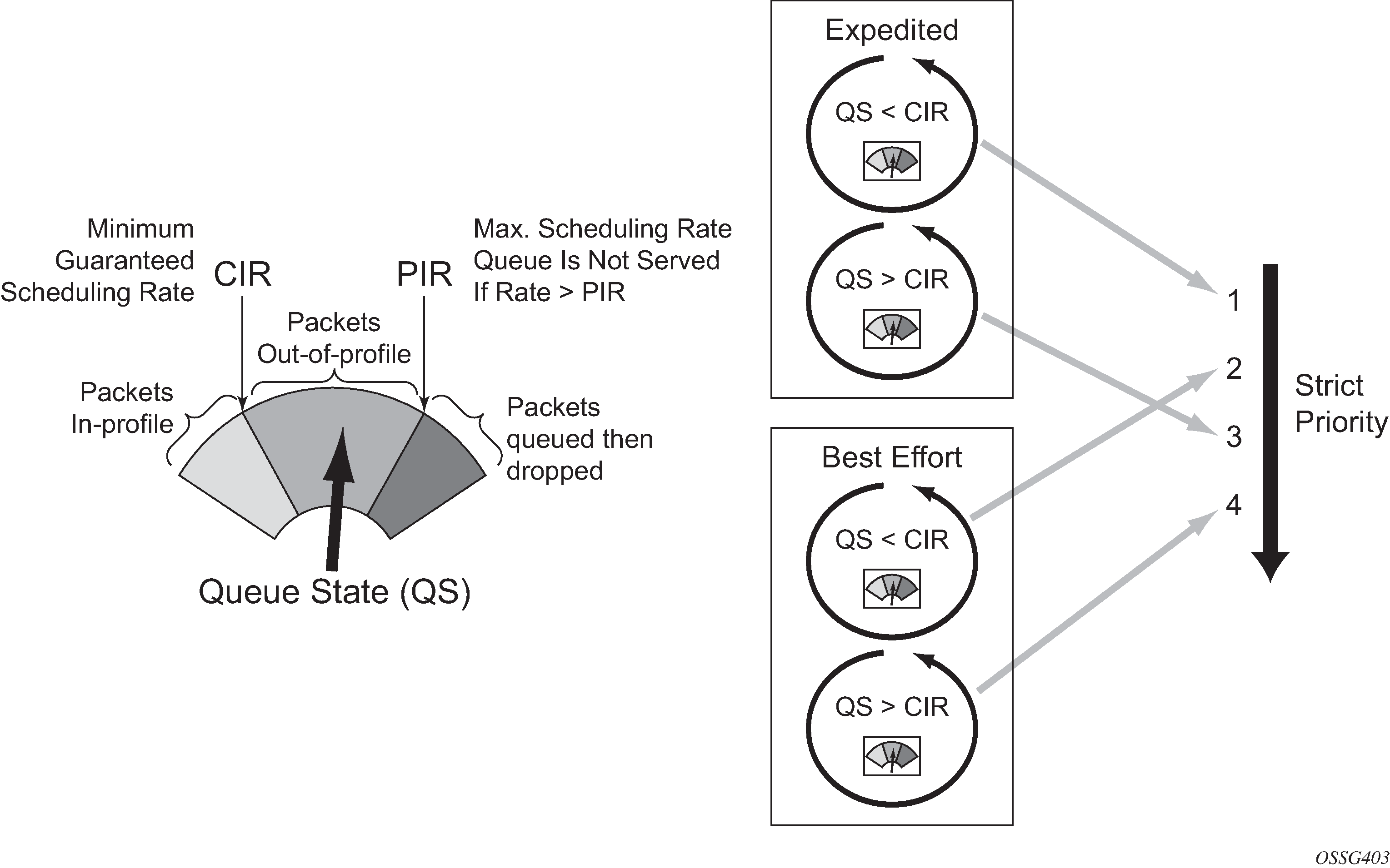
When a queue gets its turn to be serviced, the scheduler will use the operational Peak Information Rate (PIR) and Committed Information Rate (CIR) attributes of the queue to determine what to do with the packet.
The scheduler does not allow queues to exceed their configured PIR. If the packet arrival rate for a given queue is higher than the rate at which it is drained, the queue will fill. If the queue size (in bytes or Kbytes) reaches its defined MBS all subsequent packets will be discarded, this is known as tail drop.
If the dequeue rate is below or equal to the operational CIR, the packet will be forwarded and marked as in-profile.
If the dequeue rate is below or equal to the operational PIR but higher than the CIR, the packet will be forwarded but marked as out-of-profile.
Out-of-profile packets have a higher probability of being dropped when there is congestion somewhere in the downstream path. Packets that are marked as out-of-profile will also be treated differently at the network egress and service egress.
These marking actions are known as color marking (green for in-profile and yellow for out-of-profile). Using the default queue setting of priority-mode, as described above, the in/out-of-profile state of a packet is determined from the queue scheduling state (within CIR or above CIR, as described later) at the time that the packet is dequeued. An alternative queue mode is profile-mode.
Profile Mode
A queue is created with profile mode when the aim is that the in/out-of-profile state of packets is determined by the QoS bits of the incoming packets, this is known as color-aware (as opposed to color-unaware for priority mode).
As part of the classification, the profile state of the packets is explicitly configured. To provide granular control, it is possible to configure FC sub-classes with each having a different profile state, while inheriting the other parameters from their parent FC (for example the queue, in order to avoid out of order packets). The FC subclasses are named fc.sub-class, where sub-class is a text string up to 29 characters (though normally the words in and out are used for clarity). Any traffic classified without an explicit profile state is treated as if the queue were in priority mode.
When using the profile mode, the DEI in the Ethernet header can be used to classify a packet as in-profile (DEI=0) or out-of-profile (DEI=1).
The following configuration shows traffic with dot1p 3 is set to in-profile, dot1p 2 to out-of-profile and the profile state of dot1p 0 depends on the scheduling state of the queue.
configure
    qos
        sap-ingress 20 create
            queue 2 profile-mode create
            exit
            fc "af" create
                queue 2
            exit
            fc "af.in" create
                profile in
            exit
            fc "af.out" create
                profile out
            exit
            dot1p 0 fc "af"
            dot1p 2 fc "af.out"
            dot1p 3 fc "af.in"
        exit
The difference between a queue configured in priority (default) and profile mode is summarized in Queue Priority vs. Profile Mode (within/above CIR is described later).
Priority Mode |
Profile Mode |
|
|---|---|---|
Packet In-Profile/ Out-of-Profile state |
Determined by state of the queue at scheduling time. Within CIR – In Profile Above CIR – Out Profile |
Explicitly stated in FC or subclass classification. If not, then defaults to state of the queue at scheduling time |
Packet High/Low Enqueuing Priority |
Explicitly stated in FC classification. If not, then defaults to Low priority |
Always follows state of in-profile/out-of-profile determined above In-profile = High Priority Out-Profile = Low Priority If not set = High Priority |
Remarking
Remarking at the service ingress is possible when using an IES or VPRN service. The DSCP/precedence field can be remarked for in-profile (in-remark) and out-of-profile (out-remark) traffic as defined above for queues in either priority mode or profile mode. If configured for other services, the remarking is ignored. If remarking is performed at the service ingress, then the traffic is not subject to any egress remarking on the same system.
The following configuration displays an example classifying traffic to 10.0.0.0/8 as FC ef in-profile and remark its DSCP to ef.
configure
    qos
        sap-ingress 30 create
            queue 2 profile-mode create
            exit
            fc "ef" create
                queue 2
                in-remark dscp ef
                profile in
            exit
            ip-criteria
                entry 10 create
                    match
                        dst-ip 10.0.0.0/8
                    exit
                    action fc "ef"
                exit
            exit
        exit
Service Egress QoS Policy
The service egress uses a SAP egress QoS policy to define how FCs map to queues and how a packet of an FC is remarked. SAP egress policies are created in the CLI qos context and require a unique identifier (from 1 to 65535). The default SAP egress policy has identifier 1.
Once a service packet is delivered to the egress SAP, it has following attributes:
Forwarding class, determined from classification at the ingress of the node.
In/out-of-profile state from the service ingress or network ingress.
Similar to the service ingress enqueuing process, it is possible that a packet cannot get a buffer and thus gets dropped. Once on an egress queue, a packet is scheduled from the queue based on priority of the queue (expedited or best-effort) and the scheduling state with respect to the CIR/PIR rates (the profile state of the packet [in/out] is not modified here). Egress queues do not have a priority/profile mode and have no concept of multipoint.
Only one queue exists in the default SAP egress QoS policy (id=1) and also when a new sap-egress policy is created, this being queue 1 which is used for both unicast traffic and multipoint traffic. All FCs are assigned to this queue unless otherwise explicitly configured to a different configured queue. When a SAP egress policy is applied to a SAP, physical hardware queues on the FP are allocated for each queue with FC assigned (if no QoS policy is explicitly configured, the default policy is applied).
As mentioned earlier, re-classification at a SAP egress is possible based on the packet’s dot1p, DSCP or precedence values or using IP or IPv6 criteria matching, similar to the functionality at SAP ingress.
SAP egress also supports two additional profiles, inplus-profile and exceed-profile. Both can be assigned to a packet using egress reclassification and the exceed-profile can be assigned to a packet in an egress policer configured with the enable-exceed-pir command.
Traffic originated by the system (known as self generated traffic) has its FC and marking configured under router/sgt-qos (for the base routing) or under service/vprn/sgt-qos (for a VPRN service). This is beyond the scope of this chapter.
Remarking
At the service egress, the dot1p/DEI can be remarked for any service per FC with separate marking for in/out/exceed profile if required (inplus-profile packets are marked with the same value as in-profile packets and exceed-profile packets are marked with the same value as out-of-profile packets if not explicitly configured). The DEI bit can also be forced to a specific value (using the de-mark force command). When no dot1p/de-mark is configured, the ingress dot1p/DEI is preserved; if the ingress was untagged, the dot1p/DEI bit is set to 0.
The following configuration shows a remark example with different FCs with different dot1p values. FC af also differentiates between in/out-of-profile and then remarks the DEI bit accordingly based on the packet’s profile.
configure
    qos
        sap-egress 10 create
            queue 1 create
                rate 20000
            exit
            queue 2 create
                rate 10000 cir 5000
            exit
            queue 3 create
                rate 2000 cir 2000
            exit
            fc af create
                queue 2
                dot1p in-profile 3 out-profile 2
                de-mark
            exit
            fc be create
                queue 1
                dot1p 0
            exit
            fc ef create
                queue 3
                dot1p 5
            exit
        exit
If QinQ encapsulation is used, the default is to remark both tags in the same way. However, it is also possible to remark only the top tag using the qinq-mark-top-only parameter configured under the SAP egress.
The following configuration shows a remark example with only the dot1p/DEI bits in top tag of a QinQ SAP.
configure
    service
        vpls 3 customer 1 create
            sap 1/1/2:2.2 create
                egress
                    qos 20
                    qinq-mark-top-only
                exit
            exit
            no shutdown
        exit
For IES and VPRN services, the DSCP/precedence field can also be remarked based on the in/out/exceed-profile state (with inplus-profile packets marked with the same values as in-profile packets, and exceed-profile packets marked with the same value as out-of-profile packets if not explicitly configured) of the packets (and only if no ingress remarking was performed).
The following configuration shows DSCP values for FC af based on in/out-of-profile traffic.
configure
    qos
        sap-egress 20 create
            queue 2 create
            exit
            fc af create
                queue 2
                dscp in-profile af41 out-profile af43
            exit
        exit
Network Ports
The QoS policies relating to the network ports are divided into a network and a network-queue policy. The network policy covers the ingress and egress classification into FCs and the egress remarking based on FCs, while the network-queue policy covers the queues parameters and the FC to queue mapping. The logic behind this is that there is only one set of queues provisioned on a network port, whereas the use of these queues is configured per network IP interface. This in turn determines where the two policies can be applied. Network ports are used for IP routing and switching, and for GRE/MPLS tunneling.
Network QoS Policy
The network QoS policy has an ingress section and an egress section. It is created in the qos context of the CLI and requires a unique identifier (from 1 to 65535). The default network policy has identifier 1. Network QoS policies are applied to IP interfaces configured on a network port.
The following configuration shows an example to apply different network QoS policies to two network interfaces.
configure
    router
        interface "int-PE-1-PE-2"
            address 192.168.12.1/30
            port 1/1/3:1
            qos 28
        exit
        interface "int-PE-1-PE-3"
            address 192.168.13.1/30
            port 1/1/4
            qos 18
        exit
Classification
Classification is available at both ingress and egress.
The ingress section defines the classification rules for IP/MPLS packets received on a network IP interface. The rules for classifying traffic are based on the incoming QoS bits (Dot1p, DSCP, EXP [MPLS experimental bits]). The order in which classification occurs relative to these fields is:
IPv4 and IPv6 match criteria for IP packets
EXP (for MPLS packets) or DSCP (for IP packets) Dot1p/DEI bit (network ports do not support QinQ encapsulation)
default action (default = fc be profile out)
The configuration specifies the QoS bits to match against the incoming traffic together with the FC and profile (in/out) to be used (it is analogous to the SAP profile-mode in that the profile of the traffic is determined from the incoming traffic, rather than the CIR configured on the queue). A default-action keyword configures a default FC and profile state.
The IPv4 and IPv6 criteria matching only applies to the outer IP header of non-tunneled traffic, except for traffic received on an RFC 6037 MVPN tunnel for which classification on the outer IP header only is supported, and is only supported on network interfaces.
For tunneled traffic (GRE or MPLS), the match is based on the outer encapsulation header unless the keyword ler-use-dscp is configured. In this case, traffic received on the router terminating the tunnel that is to be routed to the base router or a VPRN destination is classified based on the encapsulated packet DSCP value (assuming it is an IP packet) rather than its EXP bits.
The ability exists for an egress LER to signal an implicit-null label (numeric value 3). This informs the previous hop to send MPLS packets without an outer label and so is known as penultimate hop popping (PHP). This can result in MPLS traffic being received at the termination of an LSP without any MPLS labels. In general, this would only be the case for IP encapsulated traffic, in which case the egress LER would need to classify the incoming traffic using IP criteria.
The egress section also defines the classification rules based on both the DSCP and precedence values in a packet to re-assign the packet’s FC and profile (inplus/in/out/exceed).
Remarking
The egress section of the network policy defines the remarking of the egress packets, there is no remarking possible at the network ingress. The egress remarking is configured per FC and can set the related dot1p/DEI (explicitly or dependent on in/out-of-profile), DSCP (dependent on in/out-of-profile) and EXP (dependent on in/out-of-profile; inplus-profile packets are marked with the same values as in-profile packets and exceed-profile packets are marked with the same value as out-of-profile packets).
The traffic exiting a network port is either tunneled (in GRE or MPLS) or IP routed.
For tunneled traffic exiting a network port, the remarking applies to the DSCP/EXP bits in any tunnel encapsulation headers (GRE/MPLS) pushed onto the packet by this system, together with the associated dot1p/DEI bits if the traffic has an outer VLAN tag. For MPLS tunnels, the EXP bits in the entire label stack are remarked.
Strictly speaking this is marking (as opposed to remarking) as the action is adding QoS information rather than changing it.
A new outer encapsulation header is pushed onto traffic at each MPLS transit label switched router as part of the label swap operation.
For VPLS/Epipe services no additional remarking is possible. However, for IES/VPRN/base-routing traffic, the remarking capabilities at the network egress are different at the first network egress (egress on the system on which the traffic entered by a SAP ingress) and subsequent network egress in the network (egress on the systems on which the traffic entered through another network interface).
At the first network egress, the DSCP of the routed/tunneled IP packet can be remarked, but this is dependent on two configuration settings:
The trusted state of the ingress (service/network) interface and
The remarking keyword in the network QoS policy at the network egress. The configuration combinations are summarized in Network QoS Policy DSCP Remarking .
This is in addition to the remarking of any encapsulation headers and, as stated earlier, is not performed if the traffic was remarked at the service ingress.
For traffic exiting a subsequent network egress in the network, only the IP routed traffic can be remarked, again this is dependent on the ingress trusted state and egress remarking parameter.
There is one addition to the above to handle the marking for IP-VPN Option-B in order to remark the EXP, DSCP and dot1p/DEI bits at a network egress, this being remarking force. Without this, only the EXP and dot1p/DEI bits are remarked. This does not apply to label switched path traffic switched at a label switched router.
Ingress |
Trusted State |
Remarking Configuration |
Marking Performed |
|---|---|---|---|
IES |
Untrusted (default) |
remarking |
Yes |
no remarking (default) |
Yes |
||
Trusted |
remarking |
Yes |
|
no remarking (default) |
No |
||
Network |
Untrusted |
remarking |
Yes |
no remarking (default) |
Yes |
||
Trusted (default) |
remarking |
Yes |
|
no remarking (default) |
No |
||
VPRN |
Untrusted |
remarking |
Yes |
no remarking (default) |
Yes |
||
Trusted (default) |
remarking |
No |
|
no remarking (default) |
No |
The following configuration shows a ingress network classification for DSCP EF explicitly, with a default action for the remainder of the traffic and use the DSCP from the encapsulated IP packet if terminating a tunnel. Remark the DSCP values for FC af and ef and remark all traffic (except incoming VPRN traffic) at the egress. Apply this policy to a network interface.
configure
    qos
        network 20 create
            ingress
                default-action fc af profile out
                ler-use-dscp
                dscp ef fc ef profile in
            exit
            egress
                remarking
                fc af
                    no dscp-in-profile
                    dscp-out-profile af13
                    lsp-exp-in-profile 6
                    lsp-exp-out-profile 5
                exit
                fc ef
                    dscp-in-profile af41
                exit
            exit
        exit

configure
    router
        interface "int-PE-1-PE-4"
            address 192.168.14.1/30
            port 1/2/1
            qos 20
        exit
The following configuration shows the trusted IES interface.
configure
    service
        ies 1 customer 1 create
            interface "int-access" create
                address 192.168.1.1/30
                tos-marking-state trusted
                sap 1/1/1:1 create
                exit
            exit
            no shutdown
        exit
The network QoS ingress and egress sections also contain the configuration for the use of FP-based policers and port-based queues by queue-groups which are out of scope of this chapter.
Network Queue Policy
The network queue QoS policy defines the queues and their parameters together with the FC to queue mapping. The policies are named, with the default policy having the name default. Network queues policies are applied under config>card>mda>network>ingress for the network ingress queues though only one policy is supported per MDA, so when a new policy is applied under one MDA, it is automatically applied under the other MDA on the same FP. At egress, network queue policies are applied under Ethernet: config>port>ethernet>network, POS: config>port>sonet-sdh>path>network, TDM: config>port>tdm>e3|ds3>network for the egress.
The following configuration shows an ingress and egress network-queue policy.
configure
    card 1
        card-type iom3-xp
        mda 1
            mda-type m4-10gb-xp-xfp
            network
                ingress
                    queue-policy "network-queue-1"
                exit
            exit
            no shutdown
        exit

configure
    port 1/1/3
        ethernet
            encap-type dot1q
            network
                queue-policy "network-queue-1"
            exit
        exit
        no shutdown
    exit
Up to 16 queues can be configured in a network-queue policy, each with a queue-type of best-effort, expedite, or auto-expedite. A new network-queue policy contains two queues, queue 1 for unicast traffic and queue 9 for multipoint traffic and by default all FCs are mapped to these queues. There is no differentiation for broadcast, multicast and unknown traffic. If the policy is applied to the egress, then any multipoint queues are ignored. As there are 8 FCs, there would be up to 8 unicast queues and 8 multipoint queues, resulting in 16 ingress queues and 8 egress queues. Normally, the network queue configuration is symmetric (the same queues/FC-mapping at the ingress and egress).
The following configuration defines a network-queue policy with FC af and ef assigned to queues 2 and 3 for unicast traffic, and queue 9 for multipoint traffic.
configure qos
        network-queue "network-queue-1" create
            queue 1 create
                mbs 50
                high-prio-only 10
            exit
            queue 2 create
            exit
            queue 3 create
            exit
            queue 9 multipoint create
                mbs 50
                high-prio-only 10
            exit
            fc af create
                multicast-queue 9
                queue 2
            exit
            fc ef create
                multicast-queue 9
                queue 3
            exit
        exit
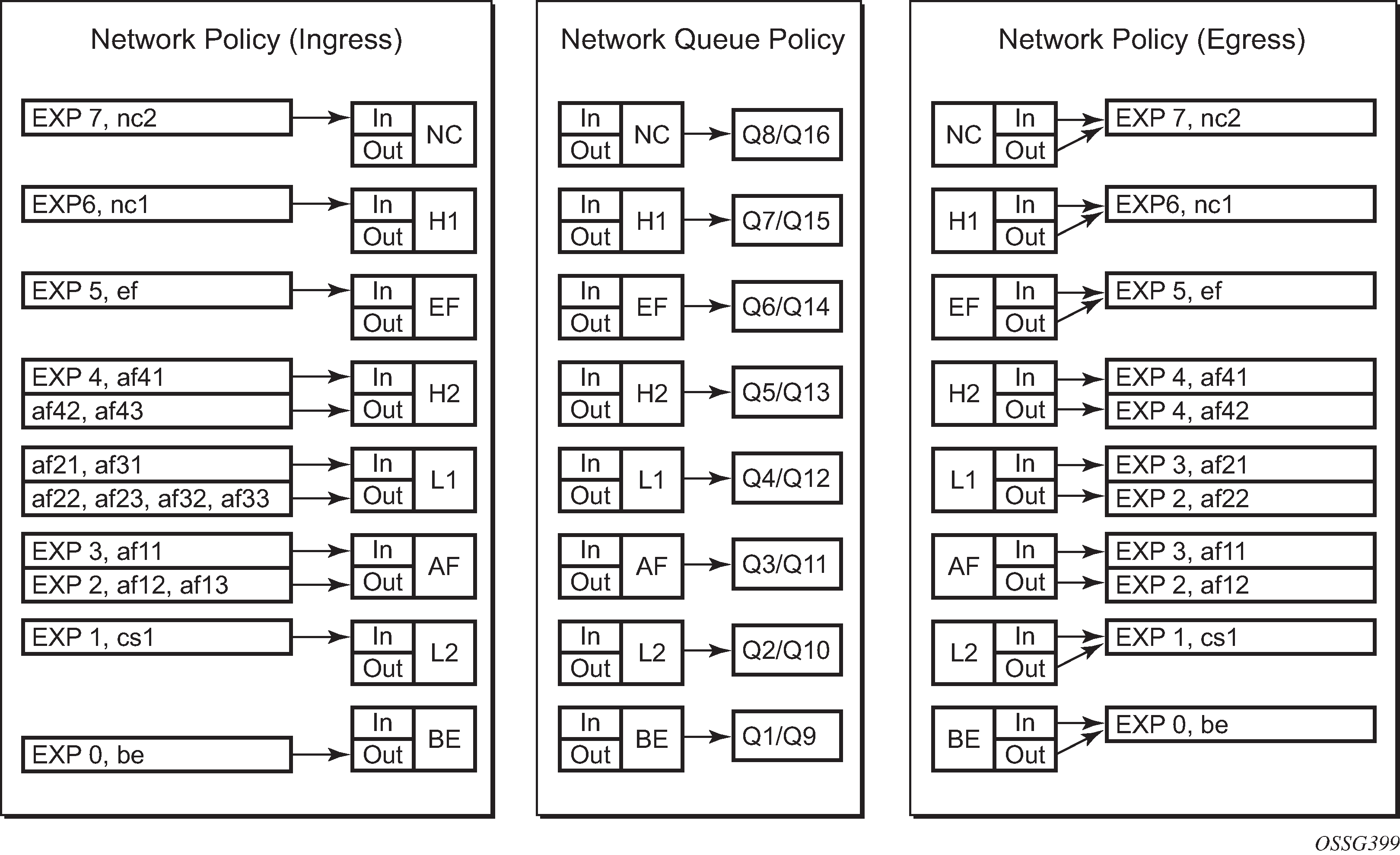
Summary of Network Policies
Visualization of Default Network Policies displays the default network policies with respect to classification, FC to queue mapping and remarking.
Queue Management
The policies described so far define queues but not the characteristics of those queues which determine how they behave. This section describes the detailed configuration associated with these queues. There are two aspects:
Enqueuing packets onto a queue
buffer pools
queue sizing
Weighted Random Early Detection (WRED)
Dequeuing packets from a queue
queue rates
scheduling
Enqueuing Packets: Buffer Pools
The packet buffer space is divided equally between ingress and egress. For line cards using a 50G FP2 for both ingress and egress traffic, the proportion of ingress versus egress buffer space can be modified using the following command:
configure
    card <slot-number>
        ingress-buffer-allocation <percentage>
The ingress buffer allocation percentage can be configured from 20% up to 80%.
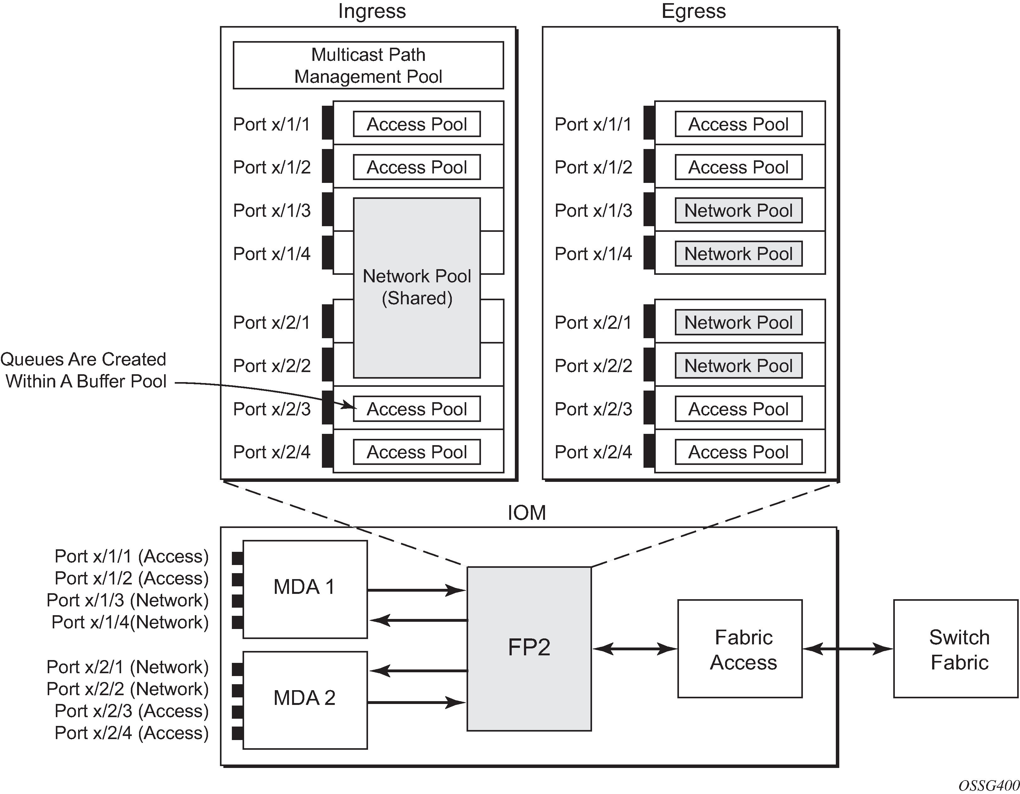
Beyond that, by default there is one pool for network ingress per FP2/IOM, with one pool per access ingress port and one pool per access/network egress port. This is shown in Default Buffer Pools. This segregation provides isolation against buffer starvation between the separate pools. An additional ingress pool exists for managed multicast traffic (the multicast path management pool) but this is beyond the scope of this chapter.
The buffer management can be modified using named buffer pools and/or WRED-per-queue pools which are out of scope of this chapter.
The size of the pools is based on the MDA type and the speed/type (access or network) of each port. Buffer space is allocated in proportion to the active bandwidth of each port, which is dependent on:
The actual speed of the port
Bandwidth for configured channels only (on channelized cards)
Zero for ports without queues configured
This calculation can be tuned separately for ingress and egress, without modifying the actual port speed, using the port/modify-buffer-allocation-rate. Changing the port’s ingress-rate or egress-rate will also modify its buffer sizes.
The following configuration changes the relative size for the ingress/egress buffer space on port 1/1/10 to 50% of the default.
configure
    port 1/1/3
        modify-buffer-allocation-rate
            ing-percentage-of-rate 50
            egr-percentage-of-rate 50
        exit
Each of the buffer pools created is further divided into a section of reserved buffers and another of shared buffers, see Ingress Buffer Pools and Queue Sizing. The amount of reserved buffers is calculated differently for network and access pools. For network pools, the default is approximately the sum of the CBS (committed burst size) values defined for all of the queues within the pool. The reserved buffer size can also be statically configured to a percentage of the full pool size (ingress: config>card>mda>network>ingress>pool; egress: config>port>network>egress>pool). For access pools, the default reserved buffer size is 30% of the full pool size and can be set statically to an explicit value (ingress: config>port>access>ingress>pool; egress: config>port>access>egress>pool).
The following configuration sets the reserved buffer size to 50% of the egress pool space on a network port.
configure
    port 1/1/3
        network
            egress
                pool
                    resv-cbs 50
                exit
            exit
        exit
On an access port, the reserved buffer size is set to 50% of the egress pool space, as follows:
configure
    port 1/1/1
        access
            egress
                pool
                    resv-cbs 50
                exit
            exit
        exit
Both the total buffer and the reserved buffer sizes are allocated in blocks (discrete values of Kbytes). The pool sizes can be seen using the show pools command.
It is possible to configure alarms to be triggered when the usage of the reserved buffers in the buffer pools reaches a certain percentage. Two alarm percentages are configurable, amber and red, amber-alarm-threshold <percentage> and red-alarm-threshold <percentage>. The percentage range is 1 — 1000.
The percentage for the red must be at least as large as that for the amber.
The alarms are cleared when the reserved CBS drops below the related threshold.
When the amber alarm is enabled, dynamic reserved buffer sizing can be used; after the amber alarm is triggered the reserved buffer size is increased or decreased depending on the CBS usage. This requires a non-default resv-cbs to be configured together with a step and max value for the amber-alarm-action parameters. As the reserved CBS usage increases above the amber alarm percentage, the reserved buffer size is increased in increments defined by the step, up to a maximum of the max. If the CBS usage decreases, the reserved buffer size is reduced in steps down to its configured size.
As the reserved buffer size changes, alarms will continue to be triggered at the same color (amber or red) indicating the new reserved buffer size. The pool sizing is checked at intervals, so it can take up to one minute for the alarms and pool re-sizing to occur.
The following displays a configuration for access ingress and egress pools.
configure
    port 1/1/1
        access
            ingress
                pool
                    amber-alarm-threshold 25
                    red-alarm-threshold 50
                    resv-cbs 20 amber-alarm-action step 5 max 50
                exit
            exit
            egress
                pool
                    amber-alarm-threshold 25
                    red-alarm-threshold 25
                    resv-cbs 20 amber-alarm-action step 5 max 50
                exit
            exit
        exit
The following is an example alarm that is triggered when the amber percentage has been exceeded and the reserved buffer size has increased from 20% to 25%:
82 2016/04/25 14:21:52.42 UTC MINOR: PORT #2050 Base Resv CBS Alarm
"Amber Alarm: CBS over Amber threshold: ObjType=port Owner=1/1/1 Type=accessIngress
 Pool=default NamedPoolPolicy= ResvSize=672 SumOfQ ResvSize=138 Old ResvCBS=20
New ResvCBS=25 Old ResvSize=528"
When a port is configured to be a hybrid port, its buffer space is divided into an access portion and a network portion. The split by default is 50:50 but it can be configured on a per port basis.
configure port 1/1/1
        ethernet
            mode hybrid
            encap-type dot1q
        exit
        hybrid-buffer-allocation
            ing-weight access 70 network 30
            egr-weight access 70 network 30
        exit
Enqueuing Packets: Queue Sizing
Queue sizes change dynamically when packets are added to a queue faster than they are removed, without any traffic the queue depth is zero. When packets arrive for a queue there will be request for buffer memory which will result in buffers being allocated dynamically from the buffer pool that the queue belongs to.
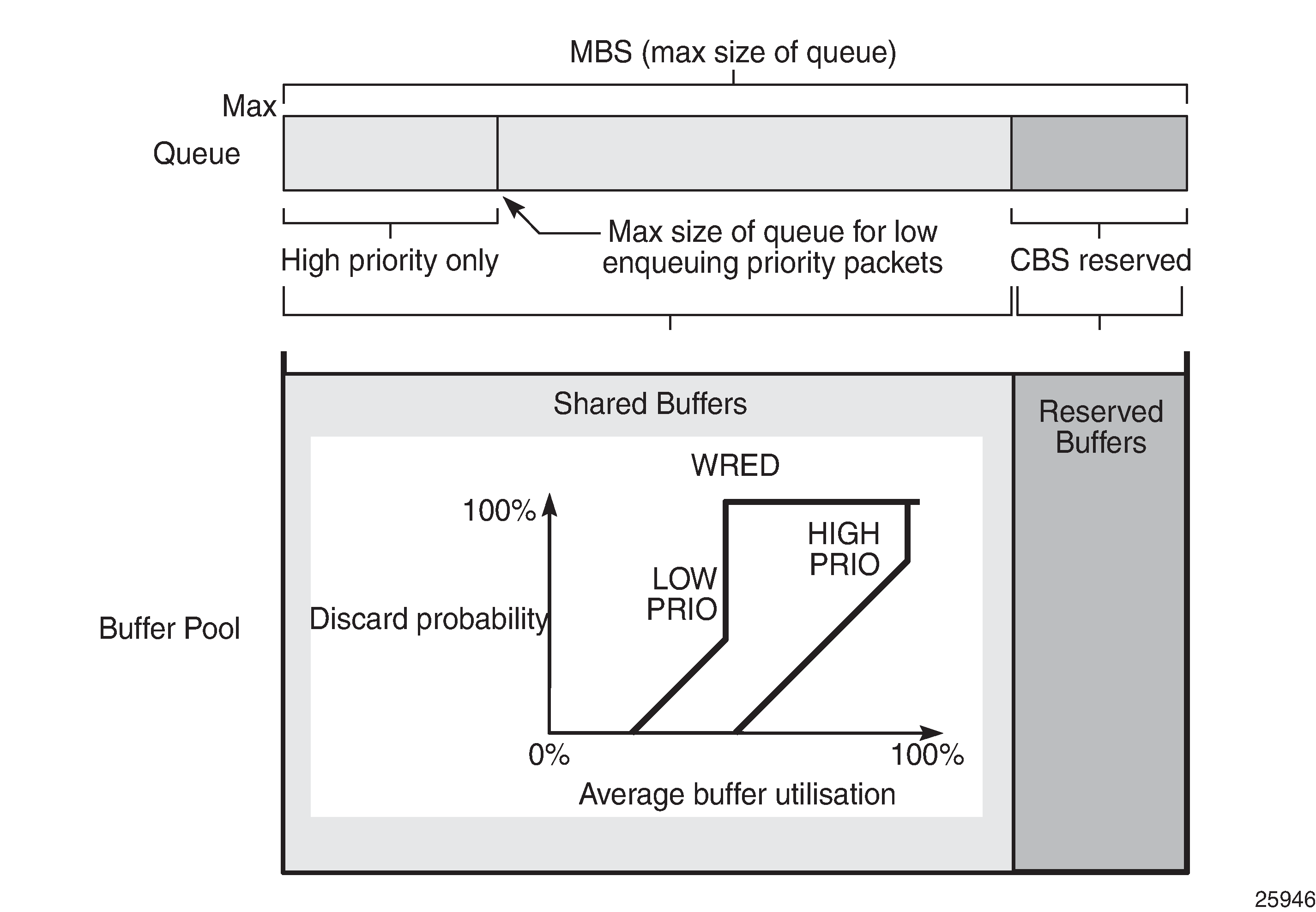
A queue has four buffer size related attributes: MBS, CBS, high-prio-only, and hi-low-prio-only, which affect packets only during the enqueuing process.
Maximum Burst Size (MBS) defines the maximum buffer size that a queue can use. If the actual queue depth is larger than the MBS, any incoming packet will not be able to get a buffer and the packet will be dropped. This is defined in bytes or Kbytes for access queues with a configurable non-zero minimum of 1byte or a default (without configuring the MBS) of the maximum between 10ms of the PIR or 64Kbytes. A value of zero will cause all packets to be dropped. MBS is a fractional percentage (xx.xx%) of pool size for network queues with defaults varying dependent on the queue (see default network-queue policy for default values). The MBS setting is the main factor determining the packet latency through a system when packets experience congestion. Queues within an egress queue group can have their MBS configured with as target packet queue delay in milliseconds.
Committed Burst Size (CBS) defines the maximum guaranteed buffer size for an incoming packet. This buffer space is effectively reserved for this queue as long as the CBS is not oversubscribed (such the sum of the CBS for all queues using this pool does not exceed its reserved buffer pool size). For access queues, the CBS is defined in Kbytes with a configurable non-zero minimum of 6Kbytes or a default (without configuring the CBS) of the maximum between 10ms of the CIR or 6Kbytes. It is a fractional percentage (xx.xx%) of pool size for network queues with defaults varying dependent on the queue (see default network-queue policy for default values). Regardless of what is configured, the CBS attained normally will not be larger than the MBS. One case where CBS could be configured larger than MBS is for queues on LAGs, because in some cases the CBS is shared among the LAG ports (LAG QoS is not covered in this chapter). If the MBS and CBS values are configured to be equal (or nearly equal) this will result in the CBS being slightly higher than the value configured.
High-prio-only. As a queue can accept both high and low enqueuing priority packets, a high enqueuing priority packet should have a higher probability to get a buffer. High-prio-only is a way to achieve this. Within the MBS, high-prio-only defines that a certain amount of buffer space will be exclusively available for high enqueuing priority packets. At network ingress and all egress buffering, highpriority corresponds to in-profile and low priority to out-of-profile. At service ingress, enqueuing priority is part of the classification. The high-prio-only is defined as a percentage of the MBS, with the default being 10%. A queue being used only for low priority/out-of-profile packets would normally have this set to zero. The high-prio-only could be considered to be an MBS for low enqueuing/out-of-profile packets.
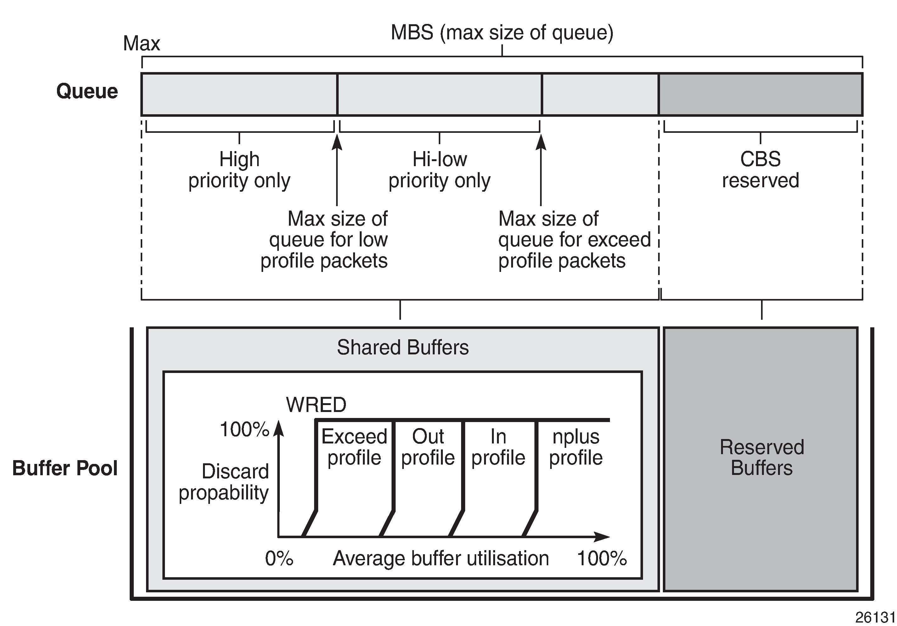
Hi-low-prio-only. There is an additional threshold, hi-low-prio-only, at egress which is equivalent to an MBS for exceed-profile packet. When the queue depth is beyond the hi-low-prio-only depth, the exceed-profile packets are dropped. The hi-low-prio-only is defined as a percentage of the MBS, with the default being 20%.
As with the buffer pools, the MBS, CBS, high-prio-only, and hi-low-prio-only values attained are based on a number of discrete values (not always an increment of 3Kbytes). The values for these parameters can be seen using the show pools command.
The MBS changes dynamically for queues in an egress queue group when H-QoS is used and the queue command dynamic-mbs is configured. This results in the MBS being modified in the ratio of the operational PIR to the admin PIR which derives an operational MBS. The ratio also affects the high-prio-only and hi-low-prio-only drop tails, and the WRED slopes if a slope policy is applied ot the queue. The configured CBS is used as the minimum operational MBS and the maximum MBS is capped by the maximum admin MBS (1GB).
As packets are added to a queue they will use the available CBS space, in which case they are placed in the reserved portion in the buffer pool. Once the CBS is exhausted, packets use the shared buffer pool space up to the hi-low-prio-only threshold (for exceed-profile packets), the high-prio-only threshold (for out-of-profile packets), or the maximum MBS size (for inplus-profile and in-profile packets).
The following configuration shows a queue with a specific MBS, CBS and disable high-prio-only.
configure
    qos
        sap-ingress 10 create
            queue 1 create
                mbs 10000
                cbs 100
                high-prio-only 0
            exit
        exit
Queue depth monitoring aims to give more visibility to the operator of the queue depths when traffic is bursty. It is a polling mechanism that is by default disabled. Queue depth monitoring can be enabled as a queue override on a service SAP or on a queue group.
The following command enables queue depth monitoring on SAP 1/1/1:11 in VPLS 10:
configure service vpls 10 sap 1/1/1:11 ingress queue-override queue 1 create monitor-depth
The result of the queue depth monitoring is presented in the form of occupancy ranges of 10% on the queue depth for each configured queue with the percentage of polls seen in each occupancy range, as follows:
*A:PE-1# show service id 10 sap 1/1/1:11 queue-depth
===============================================================================
Queue Depth Information (Ingress SAP)
===============================================================================
No Matching Entries
===============================================================================

===============================================================================
Queue Depth Information (Egress SAP)
===============================================================================
-------------------------------------------------------------------------------
Name                      : 10->1/1/1:11->1
MBS                       : Def

-------------------------------------------------------------------------------
Queue Depths (percentage)
-------------------------------------------------------------------------------
0%-10% 11%-20% 21%-30% 31%-40% 41%-50% 51%-60% 61%-70% 71%-80% 81%-90% 91%-100%
-------------------------------------------------------------------------------
68.21  3.64    3.43    3.47    3.86    3.22    3.86    2.78    3.78    3.66
-------------------------------------------------------------------------------
Average Elapsed Time      : 0d 00:39:11
Wghtd Avg PollEgr Interval: 100 ms
-------------------------------------------------------------------------------
*A:PE-1#
Enqueuing Packets: Weighted Random Early Detection (WRED)
In order to gracefully manage the use of the shared portion of the buffer pool, WRED can be configured on that part of the pool, and therefore applies to all queues in the shared pool as it fills. WRED is a congestion avoidance mechanism designed for TCP traffic. This chapter will only focus on the configuration of WRED. WRED-per-queue is an option to have WRED apply on a per egress queue basis, but is not covered here.
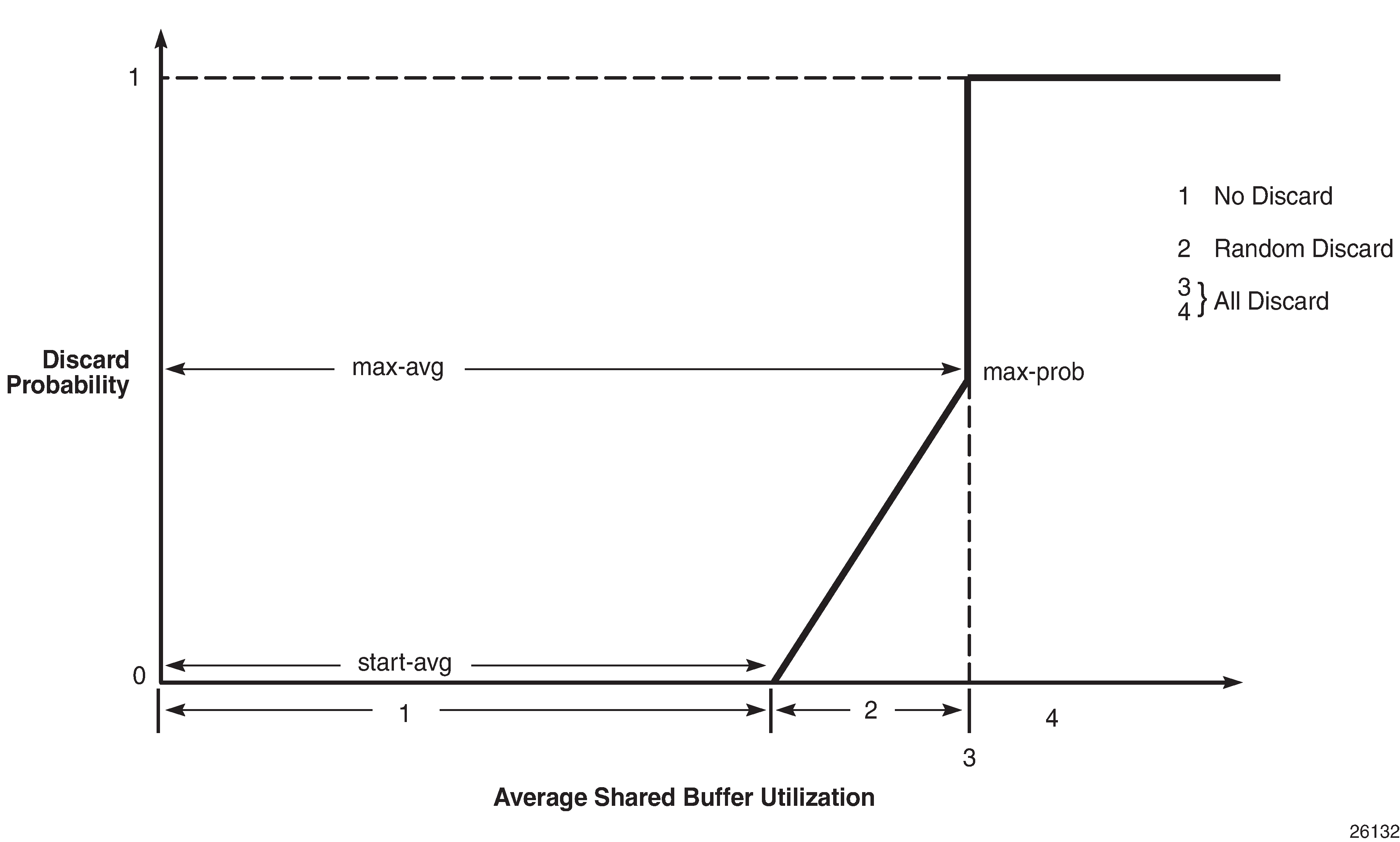
WRED is configured by a slope-policy which contains two WRED slope definitions, a high-slope which applies WRED to high enqueuing priority/in-profile packets and a low-slope which applies WRED to low enqueuing priority/out-of-profile packets. Both have the standard WRED parameters: start average (start-avg), maximum average (max-avg) and maximum probability (max-prob), and can be enabled or disabled individually. WRED slope policies also contain definitions for two slopes which are only applicable to access and network egress; a highplus-slope which applies WRED to inplus-profile packets and an exceed-slope which applies WRED to exceed-profile packets. The WRED slope characteristics are shown in WRED Slope Characteristics.
A time-average-factor parameter can be configured per slope-policy which determines the sensitivity of the WRED algorithm to shared buffer utilization fluctuations (the smaller the value makes the average buffer utilization more reactive to changes in the instantaneous buffer utilization). The slope-policy is applied on a network port under config>card>mda>network>ingress>pool and config>port>network>egress>pool and on an access port under config>port>access>ingress>pool and config>port>access>egress>pool.
WRED is usually configured for assured and best-effort service traffic with premium traffic not typically being subject to WRED as it is always given preferential treatment and should never be dropped.
The following configuration defines a WRED slope policy and applies it to an ingress access port (the highplus and exceed slopes are ignored at ingress).
configure
    qos
        slope-policy "slope1" create
            exceed-slope
                shutdown
                start-avg 30
                max-avg 55
                max-prob 80
            exit
            high-slope
                start-avg 80
                max-avg 100
                max-prob 100
                no shutdown
            exit
            highplus-slope
                shutdown
                start-avg 85
                max-avg 100
                max-prob 80
            exit
            low-slope
                max-avg 100
                start-avg 80
                max-prob 100
                no shutdown
            exit
            time-average-factor 12
        exit
configure
    port 1/1/1
        access
            ingress
                pool
                    slope-policy "slope1"
                exit
            exit
        exit
The queue sizing parameters and buffer pools layout for ingress is shown in Ingress Buffer Pools and Queue Sizing.
Egress Buffer Pools and Queue Sizing shows the queue sizing parameters and buffer pools layout for egress.
Dequeuing Packets: Queue Rates
A queue has two rate attributes: PIR and CIR. These affect packets only during the dequeue process.
PIR — If the instantaneous dequeue rate of a queue reaches this rate, the queue is no longer served. Excess packets will be discarded eventually when the queue reaches its MBS/high-prio-only/hi-low-prio-only sizes. The PIR for access ports can be set in Kb/s with a default of max or as a percentage (see below). For network ports, the PIR is set as a percentage of the sum of the capacities of network and hybrid ports on that FP (taking into account any ingress-rate configuration) for ingress queues and of the port speed for egress queues, both with a default of 100%.
CIR — The CIR is used to determine whether an ingress packet is in-profile or out-of-profile at the SAP ingress. It is also used by the scheduler in that queues operating within their CIRs will be served ahead of queues operating above their CIRs. The CIR for access ports can be set in Kb/s with a default of zero or as a percentage (see below). For network ports, it is set as a percentage of the sum of the capacities of network and hybrid ports on that FP (taking into account any ingress-rate configuration) for ingress queues and of the port speed for egress queues, with defaults varying dependent on the queue.
A percentage rate can be used in the sap-ingress and sap-egress policies, and can be defined relative to the local-limit (the parent scheduler rate) or the port-limit (the rate of the port on which the SAP is configured, including any egress-rate configured). The parameters rate and percent-rate are mutually exclusive and will overwrite each other when configured in the same policy. The following example shows a percent-rate configured as a port-limit.
configure
    qos
        sap-egress 10 create
            queue 1 create
                percent-rate 50.00 cir 10.00 port-limit
            exit
The PIR and CIR rates are shown in Scheduling (Dequeuing Packets from the Queue).
The queues operate at discrete rates supported by the hardware. If a configured rate does not match exactly one of the hardware rates an adaptation rule can be configured to control whether the rate is rounded up or down or set to the closest attainable value. The actual rate used can be seen under the operational PIR/CIR (O.PIR/O.CIR) in the show pools command output.
The following configuration shows a queue with a PIR, CIR and adaptation rule.
configure
    qos
        sap-ingress 20 create
            queue 2 profile-mode create
                adaptation-rule pir max cir min
                rate 10000 cir 5000
            exit
By default, the rates apply to packet bytes based on packet accounting, which for Ethernet includes the Layer 2 frame plus the FCS. An alternative is frame accounting which adds the Ethernet inter-frame gap, preamble and start frame delimiter.
Dequeuing Packets: Scheduling
Once a packet is placed on a queue, it is always dequeued from the queue by a scheduler. The scheduling order of the queues dynamically changes depending on whether a queue is currently operating below or above its CIR, with expedited queues being serviced before best-effort queues. This results in a default scheduling order of (in strict priority).
Expedited queues operating below CIR
Best-effort queues operating below CIR
Expedited queues operating above CIR
Best-effort queues operating above CIR
This is displayed in Scheduling (Dequeuing Packets from the Queue).
The scheduling operation can be modified using hierarchical QoS (with a scheduler-policy or port-scheduler-policy) which is out of scope of this chapter.
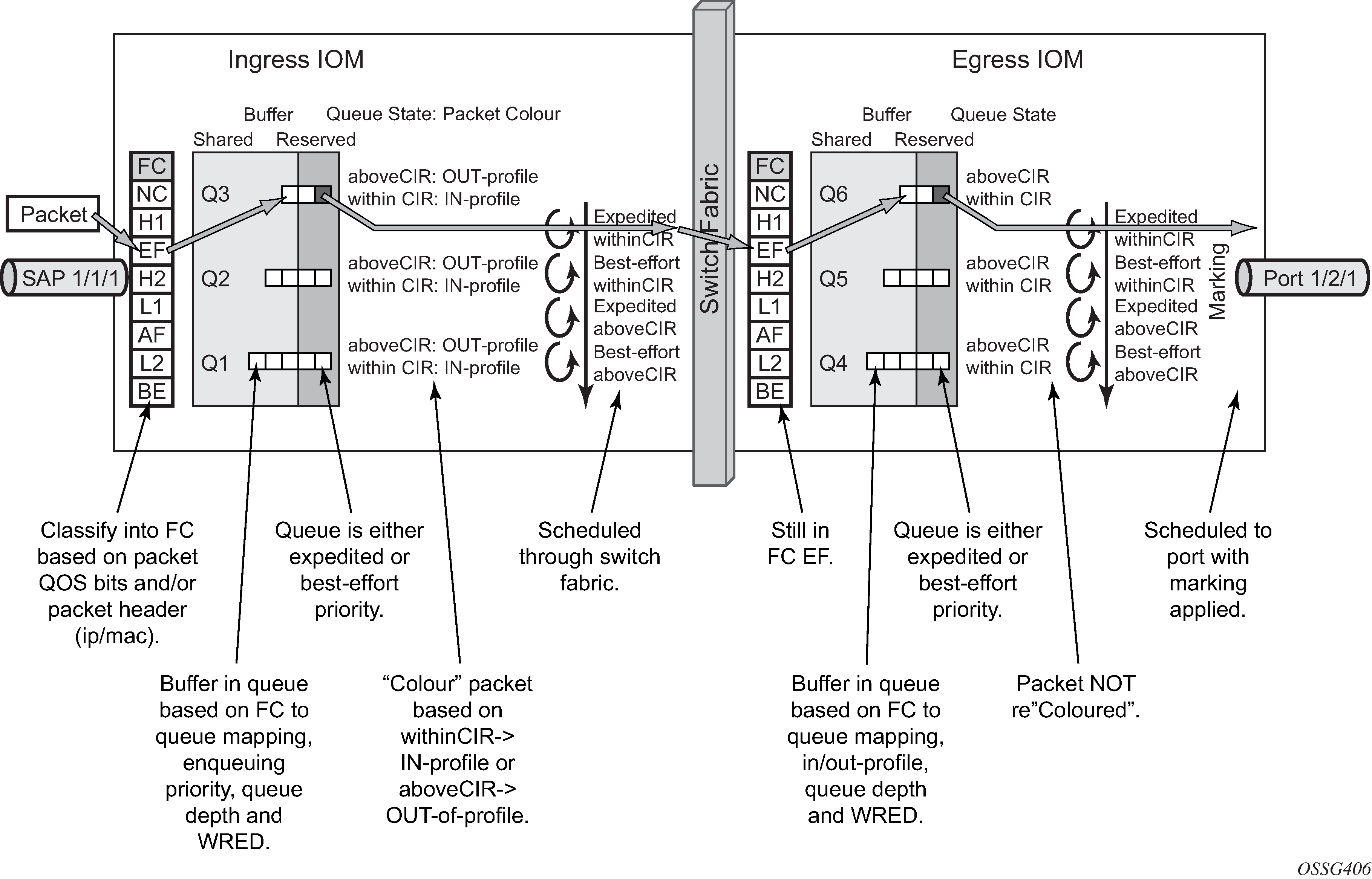
The overall QoS actions at both the ingress and egress IOMs are shown in IOM QoS Overview.
Show Output
The following displays show command output for:
SAP queue statistics
port queue statistics
per-port aggregate egress-queue statistics monitoring
access-ingress pools
The show pools command output for network-ingress and network/access-egress is similar to that of access-ingress and is not included here.
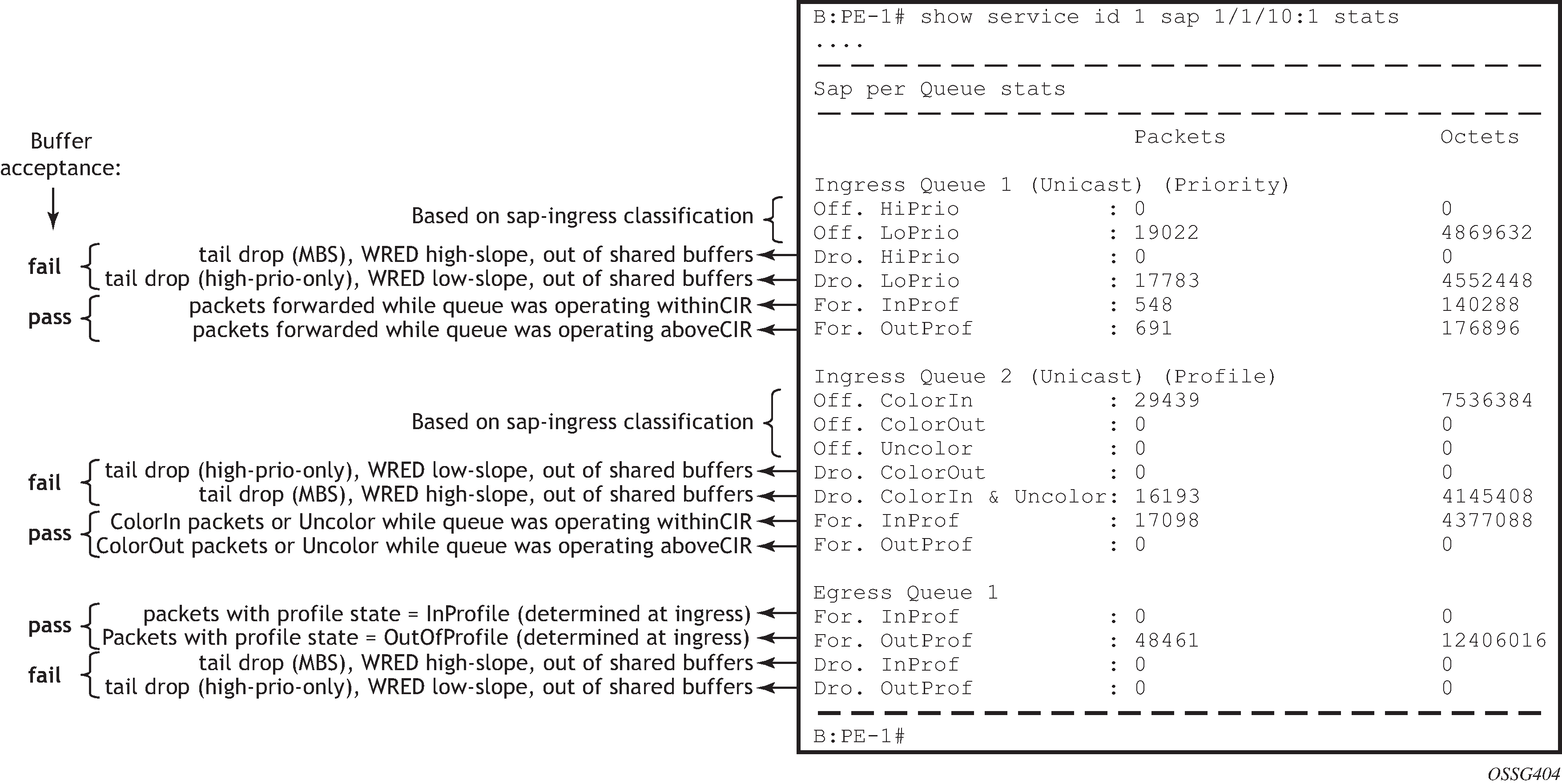
SAP Queue Statistics
The following output shows an example of the ingress and egress statistics on a SAP for an IES service (without multicast enabled, therefore no ingress multicast queue). There are two ingress queues, one being in priority mode and the other in profile mode. An explanation of the statistics is given for each entry.
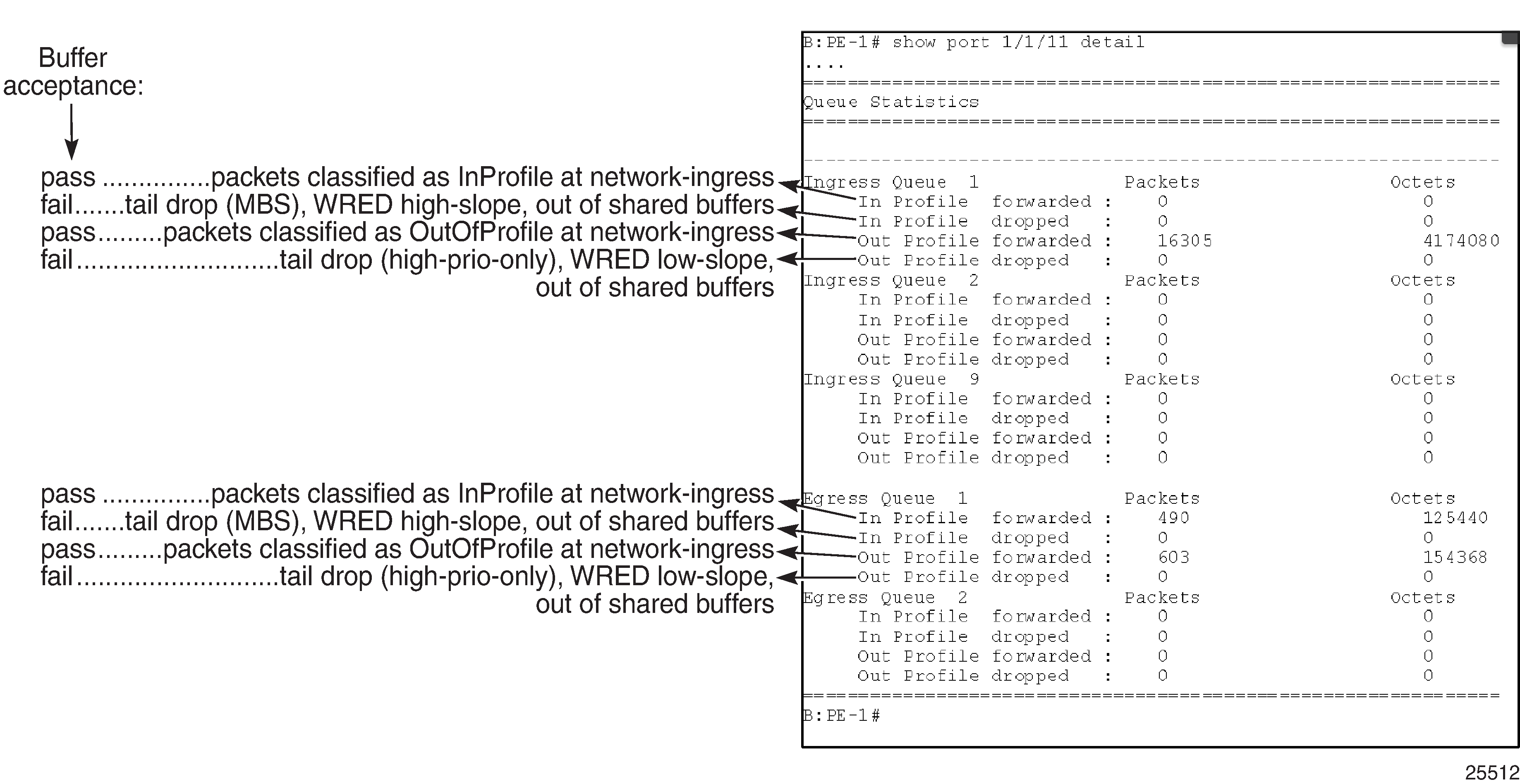
Port Queue Statistics
This output shows an example of the ingress and egress network port statistics. There are two unicast ingress queues (1 and 2) and one multicast ingress queue (9) with two egress queues. An explanation of the statistics is given for each entry.
Per-Port Aggregate Egress-Queue Statistics Monitoring
Per-port aggregate egress-queue statistics show the number of forwarded and the number of dropped packets for in-profile and out-of-profile packets. All egress queues on the port are monitored: SAP egress, network egress, subscriber egress, egress queue group queues, system queues.
Per-port aggregate egress-queue statistics monitoring is enabled with the following command:
configure port 1/1/1 monitor-agg-egress-queue-stats
The collected statistics can be displayed as follows:
*A:PE-1# show port 1/1/1 statistics egress-aggregate

===============================================================================
Port 1/1/1 Egress Aggregate Statistics on Slot 1
===============================================================================
                        Forwarded                Dropped                  Total
-------------------------------------------------------------------------------
PacketsIn                       0                      0                      0
PacketsOut                5251690                      0                5251690
OctetsIn                        0                      0                      0
OctetsOut               357114942                      0              357114942
===============================================================================
*A:PE-1#
Access-Ingress Pools
This output shows an example of the default pools output for access-ingress. It includes the pools sizes, WRED information and queue parameters for each queue in the pool.
For this particular output, queue 2 on SAP 5/1/1:1 is being over-loaded which is causing its queue depth to be 67087296 bytes, made up of 64509 Kbytes from the shared pool (in use) and 1008 Kbytes from the reserved pool (in use). The output shows the pool total in usage as 65517 Kbytes, which is the sum of the shared and reserved pool in use. Sometimes the sum and total could be different by the size of one buffer, however, this is due to the dynamics of the buffer allocation which uses a ‛sliding-window’ mechanism and may therefore not always be perfectly aligned.
It can be seen that the high, low, and exceed WRED slopes are enabled and their instantaneous drop probability is shown 100% and their max averages are 64512 Kbytes, 46080 Kbytes, and 27648 Kbytes, respectively – this shows that the reserved portion of the buffer pool on this port is exhausted causing WRED to drop the packets for this queue.
The admin and operational PIR on the overloaded queues is 10Mb/s with CIR values of zero.
*A:PE-1# show pools 5/1/1 access-ingress

===============================================================================
Pool Information
===============================================================================
Port                 : 5/1/1
Application          : Acc-Ing          Pool Name             : default
CLI Config. Resv CBS : 30%(default)
Resv CBS Step        : 0%               Resv CBS Max          : 0%
Amber Alarm Threshold: 0%               Red Alarm Threshold   : 0%
-------------------------------------------------------------------------------
Utilization                   State       Start-Avg    Max-Avg    Max-Prob
-------------------------------------------------------------------------------
High-Slope                    Up                70%        70%        100%
Low-Slope                     Up                50%        50%         80%
Exceed-Slope                  Up                30%        30%         80%
Time Avg Factor      : 12
Pool Total           : 132096 KB
Pool Shared          : 92160 KB         Pool Resv             : 39936 KB

High Slope Start Avg : 64500 KB         High Slope Max Avg    : 64512 KB
Low Slope Start Avg  : 46068 KB         Low Slope Max Avg     : 46080 KB
Excd Slope Start Avg : 27636 KB         Excd Slope Max Avg    : 27648 KB

-------------------------------------------------------------------------------

-------------------------------------------------------------------------------
Current Resv CBS    Provisioned    Rising         Falling        Alarm
%age                all Queues     Alarm Thd      Alarm Thd      Color
-------------------------------------------------------------------------------
30%                 1020 KB        NA             NA             Green
Pool Total In Use    : 65517 KB
Pool Shared In Use   : 64509 KB         Pool Resv In Use      : 1008 KB
WA Shared In Use     : 64509 KB

Hi-Slope Drop Prob   : 100              Lo-Slope Drop Prob    : 100
Excd-Slope Drop Prob : 100

===============================================================================
Queue : 1->5/1/1:1->1
===============================================================================
FC Map           : be l2 af l1 h2 h1 nc
Tap              : 5/1
Admin PIR        : 10000000             Oper PIR         : Max
Admin CIR        : 0                    Oper CIR         : 0
Admin MBS        : 12288 KB             Oper MBS         : 12288 KB
Hi Prio Only     : 1344 KB              Hi Low Prio Only : 2496 KB
CBS              : 12 KB                Depth            : 0
Slope            : not-applicable
===============================================================================

===============================================================================
Queue : 1->5/1/1:1->2
===============================================================================
FC Map           : ef
Tap              : 5/1
Admin PIR        : 10000                Oper PIR         : 10000
Admin CIR        : 0                    Oper CIR         : 0
Admin MBS        : 132096 KB            Oper MBS         : 132096 KB
Hi Prio Only     : 0 KB                 Hi Low Prio Only : 27648 KB
CBS              : 1008 KB              Depth            : 67087296 B
Slope            : not-applicable
===============================================================================

===============================================================================
Queue : 28->5/1/1:28->1
===============================================================================
FC Map           : be l2 af l1 h2 ef h1 nc
Tap              : 5/1
Admin PIR        : 10000000             Oper PIR         : Max
Admin CIR        : 0                    Oper CIR         : 0
Admin MBS        : 12288 KB             Oper MBS         : 12288 KB
Hi Prio Only     : 1344 KB              Hi Low Prio Only : 2496 KB
CBS              : 0 KB                 Depth            : 0
Slope            : not-applicable
===============================================================================

===============================================================================
Queue : 28->5/1/1:28->11
===============================================================================
FC Map           : be l2 af l1 h2 ef h1 nc
Tap              : MCast
Admin PIR        : 10000000             Oper PIR         : Max
Admin CIR        : 0                    Oper CIR         : 0
Admin MBS        : 12288 KB             Oper MBS         : 12288 KB
Hi Prio Only     : 1344 KB              Hi Low Prio Only : 2496 KB
CBS              : 0 KB                 Depth            : 0
Slope            : not-applicable
===============================================================================
===============================================================================

*A:PE-1#
Conclusion
This chapter has described the basic QoS functionality available on the Nokia 7x50 platforms, specifically focused on the FP2 chipset. This comprises of the use of queues to shape traffic at the ingress and egress of the system and the classification, buffering, scheduling and remarking of traffic on access, network, and hybrid ports.