G.8032 Ethernet Ring Protection Single Ring Topology
This chapter provides information about G.8032 Ethernet ring protection single ring topology.
Topics in this chapter include:
Applicability
The chapter was initially written for SR OS Release 8.0.R7, but the CLI in the current edition corresponds to SR OS Release 23.3.R2. This chapter describes ring protection for a single ring topology. Protection for multiple ring topologies is covered in G.8032 Ethernet Ring Protection Multiple Ring Topology.
Overview
G.8032 Ethernet ring protection is supported for data service SAPs within a regular VPLS service, a provider backbone bridging (PBB) VPLS (I/B-component), or a routed VPLS (R-VPLS). G.8032 is one of the fastest protection schemes for Ethernet networks.
ITU-T G.8032v2 specifies protection switching mechanisms and a protocol for Ethernet layer network (ETH) Ethernet rings. Ethernet rings can provide wide-area multi-point connectivity more economically due to their reduced number of links. The mechanisms and protocol defined in ITU-T G.8032v2 achieve highly reliable and stable protection and never form loops, which would negatively affect network operation and service availability. Each ring node is connected to adjacent nodes participating in the same ring using two independent paths, which use ring links that are configured on ports or link aggregation groups (LAGs). A ring link is bounded by two adjacent nodes and a port for a ring link is called a ring port. The minimum number of nodes on a ring is two.
The fundamentals of this ring protection switching architecture are:
the principle of loop avoidance and
the utilization of learning, forwarding, and address table mechanisms defined in the ITU-T G.8032v2 Ethernet flow forwarding function (ETH_FF) (control plane).
Loop avoidance in the ring is achieved by guaranteeing that, at any time, traffic may flow on all but one of the ring links. This particular link is called the ring protection link (RPL) and under normal conditions this link is blocked, so it is not used for traffic. One designated node, the RPL owner, is responsible to block traffic over the one designated RPL. Under a ring failure condition, the RPL owner is responsible for unblocking the RPL, allowing the RPL to be used for traffic. The protocol ensures that even without an RPL owner defined, one link will be blocked and it operates as a break before make protocol, specifically the protocol guarantees that no link is restored until a different link in the ring is blocked. The other side of the RPL is configured as an RPL neighbor. An RPL neighbor blocks traffic on the link.
The event of a ring link or ring node failure results in protection switching of the traffic. This is achieved under the control of the ETH_FF functions on all ring nodes. A ring automatic protection switching (R-APS) protocol is used to coordinate the protection actions over the ring. The protection switching mechanisms and protocol supports a multi-ring/ladder network that consists of connected Ethernet rings, however, that is not covered in this chapter.
Ring protection mechanism
The ring protection protocol is based on the following building blocks:
ring status change on failure
idle → link failure → protection → recovery → idle
ring control state changes
idle → protection → manual switch → forced switch → pending
re-use existing ETH OAM
monitoring: ETH continuity check messages
failure notification: Y.1731 signal failure
forwarding database MAC flush on ring status change
ring protection link (RPL) defines blocked link in idle status
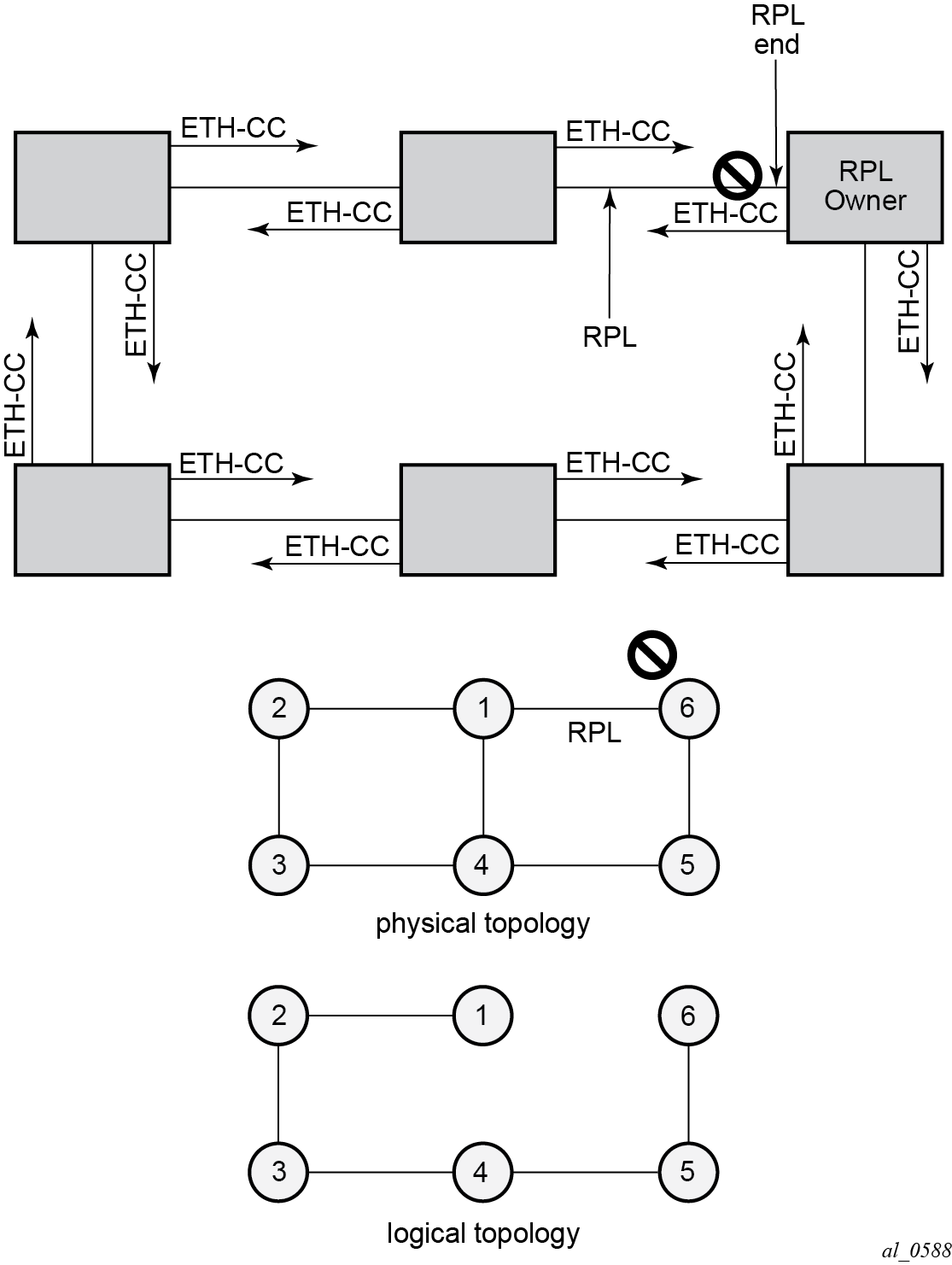
G.8032 operation and topologies shows a ring of six nodes, with the RPL owner on the top right. One link of the RPL owner is designated to be the RPL and will be blocked in order to prevent a loop. Schematics of the physical and logical topologies are also shown.
When an RPL owner and RPL end are configured, the associated link will be the RPL when the ring is fully operational and so be blocked by the RPL owner. If a different ring link fails, then the RPL will be unblocked by the RPL owner. When the failed link recovers, it will initially be blocked by one of its adjacent nodes. The adjacent node sends an R-APS message across the ring to indicate the error is cleared and after a configurable time, if reversion is enabled, the RPL will revert to being blocked with all other links unblocked. This ensures that the ring topology is predictable when fully operational.
If a specific RPL owner is not configured, then the last link to become active will be blocked and the ring will remain in this state until another link fails. However, this operation makes the selection of the blocked link non-deterministic.
The protection protocol uses a specific control VLAN, with the associated data VLANs taking their forwarding state from the control VLAN.
Configuration
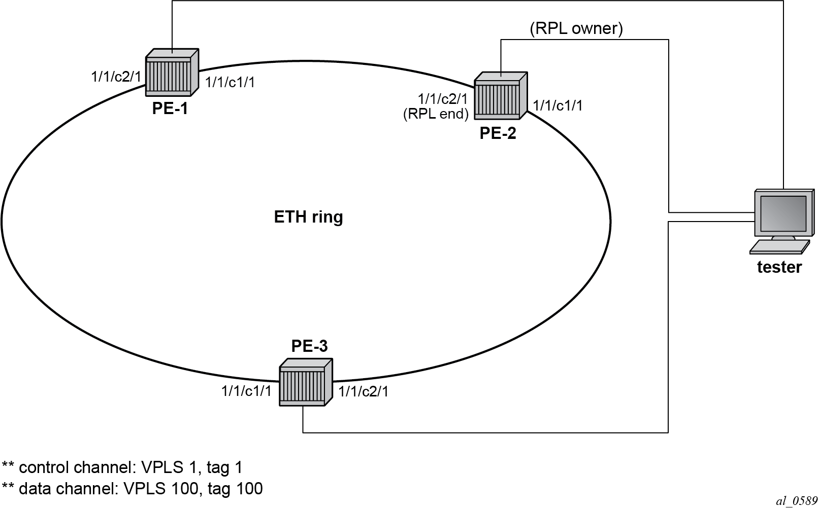
The example topology is shown in Example topology.
The Ethernet ring configuration commands are as follows:
configure
    eth-ring <ring-index [1..128]>
        ccm-hold-time { [down <down-timeout>] [up <up-timeout>] }
        compatible-version <version>            # [1..2] - Default: 2
        description <description-string>
        guard-time <time>       # [1..20] in deciseconds - Default: 5
        node-id <xx:xx:xx:xx:xx:xx or xx-xx-xx-xx-xx-xx>
        path {a|b} [ { <port-id>|<lag-id> } raps-tag <qtag1>[.<qtag2>] ]
            description <description-string>
            eth-cfm
                mep <mep-id> domain <md-index> association <ma-index>
                <...>
            rpl-end
            shutdown
        revert-time <time>      # [60..720] in seconds - Default: 300
        rpl-node {owner|nbr}
        shutdown
        sub-ring {virtual-link|non-virtual-link}       # beyond the scope
Parameters:
ring-index — This is the number by which the ring is referenced, values: 1 to 128.
ccm-hold-time {[down <down-timeout>] [up <up-timeout>]}
down — This command specifies the timer that controls the delay between detecting that ring path is down and reporting it to the G.8032 protection module. If a non-zero value is configured, the system will wait for the time specified in the value parameter before reporting it to the G.8032 protection module. This parameter applies only to the ring path continuity check message (CCM); it does not apply to the ring port link state. To dampen ring port link state transitions, use the hold-time parameter from the physical member port. This is useful if the underlying path between two nodes is going across an optical system which implements its own protection.
up — This command specifies the timer which controls the delay between detecting that the ring path is up and reporting it to the G.8032 protection module. If a non-zero value is configured, the system will wait for the time specified in the value parameter before reporting it to the G.8032 protection module. This parameter applies only to ring path CCM; it does not apply to the member port link state. To dampen member port link state transitions, use the hold-time parameter from the physical member port.
timeout values:
 <down-timeout>       : [0..5000] in 100ths of seconds - Default: 0
 <up-timeout>         : [0..5000] in 10ths of seconds - Default: 20
compatible version — This command configures the Ethernet ring compatibility version for the G.8032 state machine and messages. The default is version 2 (ITU G.8032v2) and all SR OS nodes use version 2. If there is a need to interwork with third party devices that only support version 1, this can be set to version 1 allowing the reception of version 1 PDUs. Version 2 is encoded as 1 in the R-APS messages. Compatibility allows the reception of version 1 (encoded as 0) R-APS PDUs but, as per the G.8032 specification, higher versions are ignored on reception. For SR OS nodes, messages are always originated with version 2. Therefore, if a third party switch supported version 3 (encoded as 2) or higher, interworking is also supported provided the other switch is compatible with version 2 (encoded as 1).
description <description-string> — This configures a text string, up to 80 characters, which can be used to describe the use of the Ethernet ring.
guard-time <time> — The forwarding method, in which R-APS messages are copied and forwarded at every Ethernet ring node, can result in a message corresponding to an old request, that is no longer relevant, being received by Ethernet ring nodes. Reception of an old R-APS message may result in erroneous ring state interpretation by some Ethernet ring nodes. The guard timer is used to prevent Ethernet ring nodes from acting upon outdated R-APS messages and prevents the possibility of forming a closed loop. Messages are not forwarded when the guard-timer is running.
The guard time is configured in 10ths of seconds and the default guard time is 0.5 s:
[1..20] in deciseconds - Default: 5node-id <xx:xx:xx:xx:xx:xx or xx-xx-xx-xx-xx-xx> — The node identifier can be explicitly configured. In typical configurations, the node ID is not configured; by default, the chassis MAC address is used as node ID.
path {a|b} [{<port-id>|<lag-id>} raps-tag <qtag1>[.<qtag2>]] — The path parameter defines the paths around the ring, of which there are two in different directions on the ring: an "a" path and a "b" path. In addition, the path command configures the encapsulation used for the R-APS messages on the ring. These can be either single or double tagged.
description <description-string> — The description is a text string with up to 80 characters, that can be used to describe the use of the path.
eth-cfm — Configures the associated Ethernet connectivity fault management (CFM) parameters.
mep <mep-id> domain <md-index> association <ma-index> — The maintenance endpoint (MEP) defined under the path is used for the G.8032 protocol messages, which are based on IEEE 802.1ag/Y.1731 CFM frames.
rpl-end — When configured, this path is expected to be one end of the RPL. This parameter must be configured in conjunction with the rpl-node.
shutdown — This command disables the path.
revert-time <time> — This command configures the revert time for an Ethernet ring. The revert time is the time that the RPL will wait before returning to the blocked state. Configuring no revert-time disables reversion, effectively setting the revert-time to zero.
Values:
[60..720] in seconds - Default: 300rpl-node {owner|nbr} — A node can be designated as either the owner of the RPL, in which case this node is responsible for the RPL, or the nbr, in which case this node is expected to be the neighbor to the RPL owner across the RPL. The neighbor is optional and is included to be compliant with the specification. This parameter must be configured in conjunction with the rpl-end parameter.
shutdown — This command disables the ring.
sub-ring {virtual-link|non-virtual-link} — The sub-ring command is beyond the scope of this chapter because it is only required for multiple ring topologies.
Logging
Create following log-id on PE-2 to see major events logged to the console on PE-2. This is an optional step; alternatively, log 99 can be consulted.
# on PE-2:
configure
    log
        log-id 1 name "log1"
            from main
            to console
        exit
    exit
Configure encapsulation for ring ports
To configure R-APS, there should be at least two VPLS services for one Ethernet ring instance, one VPLS for the control channel and the other VPLSs for data channels. The control channel is used for R-APS signaling while the data channel is for user data traffic. The state of the data channels is inherited from the state of the control channel.
An Ethernet ring needs R-APS tags to send and receive G.8032 signaling messages. To configure a control channel, an access SAP configuration is required on each path a port and path b port. The SAP configuration follows that of the port and must be either dot1Q or QinQ, so the control and data packets are either single tagged or double tagged. It is also possible to have the control VPLS using single tagged frames with the data VPLSs using double tagged frames; this requires the system to be configured with the new-qinq-untagged-sap parameter (configure system ethernet new-qinq-untagged-sap), with the ring path R-APS tags and control VPLS SAPs configured as qtag.0, and the data VPLS SAPs configured as qtag1.qtag2.
In this example, single tags are used so the ports on the ring nodes are configured as follows:
# on PE-1, PE-2, PE-3:
configure
    port 1/1/c1/1
        ethernet
            mode access
            encap-type dot1q
        exit
        no shutdown
    exit
    port 1/1/c2/1
        ethernet
            mode access
            encap-type dot1q
        exit
        no shutdown
    exit
Configure Ethernet CFM
Ethernet ring requires Ethernet CFM domains, associations, and MEPs being configured. The domain format must be none and association name must be ITU-T carrier code-based (ICC-based - Y.1731). The minimum CCM interval for the SR OS nodes is 10ms. The Ethernet ring MEP requires a CCM interval, such as 10ms, 100ms, or 1s, to be configured.
The MEPs used for R-APS control normally have CCM configured on the control channel path MEPs for failure detection. Alternatively, detecting a failure of the ring may be achieved by running Ethernet in the first mile (EFM) at the port level if CCM is not possible at 10ms, 100ms, or 1s. Loss-of-signal, in conjunction with other OAM, is applicable only when the nodes are directly connected.
To omit the failure detecting CCMs, remove the ccm-enable from under the path MEPs and remove the remote-mepid from under the eth-cfm>domain>association on all nodes.
Ethernet CFM configuration shows the Ethernet CFM configuration used here.
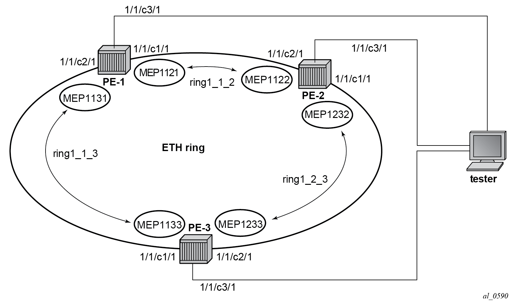
The Ethernet CFM configuration of the nodes is as follows.
# on PE-1:
configure
    eth-cfm
        domain 1 format none level 3 admin-name "domain-1"
            association 1 format icc-based name "ring1_1_2" admin-name "association-1"
                ccm-interval 1
                remote-mepid 1122
            exit
            association 2 format icc-based name "ring1_1_3" admin-name "association-2"
                ccm-interval 1
                remote-mepid 1133
            exit
        exit
# on PE-2:
configure
    eth-cfm
        domain 1 format none level 3 admin-name "domain-1"
            association 1 format icc-based name "ring1_2_3" admin-name "association-1"
                ccm-interval 1
                remote-mepid 1233
            exit
            association 2 format icc-based name "ring1_1_2" admin-name "association-2"
                ccm-interval 1
                remote-mepid 1121
            exit
        exit
# on PE-3:
configure
    eth-cfm
        domain 1 format none level 3 admin-name "domain-1"
            association 1 format icc-based name "ring1_1_3" admin-name "association-1"
                ccm-interval 1
                remote-mepid 1131
            exit
            association 2 format icc-based name "ring1_2_3" admin-name "association-2"
                ccm-interval 1
                remote-mepid 1232
            exit
        exit
Configure Ethernet ring
Two paths need to be configured to form a ring. In this example, VLAN tag 1 is used as control channel for R-APS signaling in the ring.
# on PE-1:
configure
    eth-ring 1
        path a 1/1/c1/1 raps-tag 1
            eth-cfm
                 mep 1121 domain 1 association 1
                    ccm-enable
                    control-mep
                    no shutdown
                exit
            exit
            no shutdown
        exit
        path b 1/1/c2/1 raps-tag 1
            eth-cfm
                mep 1131 domain 1 association 2
                    ccm-enable
                    control-mep
                    no shutdown
                exit
            exit
            no shutdown
        exit
        no shutdown
    exit
It is mandatory to configure a MEP in the path context, otherwise the following error will be displayed:
*A:PE-1>config>eth-ring# path a 1/1/c1/1 raps-tag 1
*A:PE-1>config>eth-ring>path# no shutdown
INFO: ERMGR #1001 Not permitted - must configure eth-cfm MEP first
While MEPs are mandatory, enabling CCM on the MEP in the path context as a failure detection mechanism is optional.
In order to define the RPL, node PE-2 is configured as the RPL owner and path b as the RPL end. The link between nodes PE-1 and PE-2 will be the RPL with node PE-2 blocking that link when the ring is fully operational.
# on PE-2:
configure
    eth-ring 1
        revert-time 60
        rpl-node owner
        path a 1/1/c1/1 raps-tag 1
            eth-cfm
                mep 1232 domain 1 association 1
                    ccm-enable
                    control-mep
                    no shutdown
                exit
            exit
            no shutdown
        exit
        no shutdown
        path b 1/1/c2/1 raps-tag 1
            rpl-end
            eth-cfm
                mep 1122 domain 1 association 2
                    ccm-enable
                    control-mep
                    no shutdown
                exit
            exit
            no shutdown
        exit
        no shutdown
    exit
It is not allowed to configure a path as an RPL end without having configured the node on this ring to be either the RPL owner or nbr otherwise the following error message is reported.
*A:PE-2>config>eth-ring>path# rpl-end
INFO: ERMGR #1001 Not permitted - path-type rpl-end is not consistent with eth-ring 'rpl-node' type
# on PE-3:
configure
    eth-ring 1
        path a 1/1/c1/1 raps-tag 1
            eth-cfm
                mep 1133 domain 1 association 1
                    ccm-enable
                    control-mep
                    no shutdown
                exit
            exit
            no shutdown
        exit
        path b 1/1/c2/1 raps-tag 1
            eth-cfm
                mep 1233 domain 1 association 2
                    ccm-enable
                    control-mep
                    no shutdown
                exit
            exit
            no shutdown
        exit
        no shutdown
    exit
Until the Ethernet ring instance is attached to the service (VPLS in this case), the ring operational status is down and the forwarding status of each port is blocked. This prevents operators from creating a loop by misconfiguration. This state can be seen on ring node PE-1 as follows:
*A:PE-1# show eth-ring 1

===============================================================================
Ethernet Ring 1 Information
===============================================================================
Description        : (Not Specified)
Admin State        : Up                 Oper State       : Down
Node ID            : 02:09:ff:00:00:00
Guard Time         :    5 deciseconds   RPL Node         : rplNone
Max Revert Time    :  300 seconds       Time to Revert   : N/A
CCM Hold Down Time :    0 centiseconds  CCM Hold Up Time :   20 deciseconds
Compatible Version : 2
APS Tx PDU         : Request State: 0xB
                     Sub-Code     : 0x0
                     Status       : 0x20  ( BPR )
                     Node ID      : 02:09:ff:00:00:00
Defect Status      :

Sub-Ring Type      : none

-------------------------------------------------------------------------------
Ethernet Ring Path Summary
-------------------------------------------------------------------------------
Path Port             Raps-Tag     Admin/Oper      Type            Fwd State
-------------------------------------------------------------------------------
  a  1/1/c1/1         1               Up/Down      normal          blocked
  b  1/1/c2/1         1               Up/Down      normal          blocked
===============================================================================
Configure control channel VPLS service
Paths a and b defined in the Ethernet ring must be added as SAPs into a VPLS service (standard VPLS in this example) using the eth-ring parameter. The SAP encapsulation values must match the values of the raps-tag configured for the associated path.
G.8032 uses the same R-APS tag value on all nodes on the ring, as configured in this example. However, the SR OS implementation relaxes this constraint by requiring the tag to match only on adjacent nodes.
# on PE-1:
configure
    service
        vpls 1 name "VPLS-1" customer 1 create
            description "control channel VPLS 1 tag 1"
            sap 1/1/c1/1:1 eth-ring 1 create
            exit
            sap 1/1/c2/1:1 eth-ring 1 create
            exit
            no shutdown
        exit
# on PE-2:
configure
    service
        vpls 1 name "VPLS-1" customer 1 create
            description "control channel VPLS 1 tag 1"
            sap 1/1/c1/1:1 eth-ring 1 create
            exit
            sap 1/1/c2/1:1 eth-ring 1 create
            exit
            no shutdown
        exit
# on PE-3:
configure
    service
        vpls 1 name "VPLS-1" customer 1 create
            description "control channel VPLS 1 tag 1"
            sap 1/1/c1/1:1 eth-ring 1 create
            exit
            sap 1/1/c2/1:1 eth-ring 1 create
            exit
            no shutdown
        exit
A normal SAP or SDP can be added in a control channel VPLS on condition the eth-ring parameter is present. Any attempt to add a SAP or SDP without this parameter into a control channel VPLS results in the following message being displayed. In the following example, SAP 1/1/c3/1:1 is added to control VPLS 1 without the eth-ring parameter.
*A:PE-1>config>service>vpls# sap 1/1/c3/1:1 create
MINOR: SVCMGR #1321 Service contains an Ethernet ring control SAP
In non-failure conditions, the Ethernet ring is operationally up and the RPL is blocking successfully on ring node PE-2 port 1/1/c2/1, as expected from the RPL owner and RPL end configuration.
An overview of all of the rings can be shown using the following commands, in this case on node PE-2.
The following command on PE-2 shows the Ethernet ring status.
*A:PE-2# show eth-ring status

===============================================================================
Ethernet Ring (Status information)
===============================================================================
Ring   Admin  Oper       Path Information                 MEP Information
ID     State  State  Path         Tag       State     Ctrl-MEP CC-Intvl Defects
-------------------------------------------------------------------------------
1      Up     Up     a - 1/1/c1/1     1     Up        Yes      1         -----
                     b - 1/1/c2/1     1     Up        Yes      1         -----
===============================================================================
Ethernet Tunnel MEP Defect Legend:
R = Rdi, M = MacStatus, C = RemoteCCM, E = ErrorCCM, X = XconCCM
The following command shows the ring and path forwarding states.
*A:PE-2# show eth-ring

===============================================================================
Ethernet Rings (summary)
===============================================================================
Ring Int  Admin Oper            Paths Summary                       Path States
ID   ID   State State                                               a     b
-------------------------------------------------------------------------------
1    -    Up    Up    a - 1/1/c1/1     1     b - 1/1/c2/1     1     U     B
===============================================================================
Ethernet Ring Summary Legend:   B - Blocked    U - Unblocked
The show eth-ring 1 command on the different nodes shows specific information for Ethernet ring 1:
*A:PE-1# show eth-ring 1

===============================================================================
Ethernet Ring 1 Information
===============================================================================
Description        : (Not Specified)
Admin State        : Up                 Oper State       : Up
Node ID            : 02:09:ff:00:00:00
Guard Time         :    5 deciseconds   RPL Node         : rplNone
Max Revert Time    :  300 seconds       Time to Revert   : N/A
CCM Hold Down Time :    0 centiseconds  CCM Hold Up Time :   20 deciseconds
Compatible Version : 2
APS Tx PDU         : N/A
Defect Status      :

Sub-Ring Type      : none

-------------------------------------------------------------------------------
Ethernet Ring Path Summary
-------------------------------------------------------------------------------
Path Port             Raps-Tag     Admin/Oper      Type            Fwd State
-------------------------------------------------------------------------------
  a  1/1/c1/1         1               Up/Up        normal          unblocked
  b  1/1/c2/1         1               Up/Up        normal          unblocked
===============================================================================
*A:PE-2# show eth-ring 1

===============================================================================
Ethernet Ring 1 Information
===============================================================================
Description        : (Not Specified)
Admin State        : Up                 Oper State       : Up
Node ID            : 02:0b:ff:00:00:00
Guard Time         :    5 deciseconds   RPL Node         : rplOwner
Max Revert Time    :   60 seconds       Time to Revert   : N/A
CCM Hold Down Time :    0 centiseconds  CCM Hold Up Time :   20 deciseconds
Compatible Version : 2
APS Tx PDU         : Request State: 0x0
                     Sub-Code     : 0x0
                     Status       : 0xA0  ( RB BPR )
                     Node ID      : 02:0b:ff:00:00:00
Defect Status      :

Sub-Ring Type      : none

-------------------------------------------------------------------------------
Ethernet Ring Path Summary
-------------------------------------------------------------------------------
Path Port             Raps-Tag     Admin/Oper      Type            Fwd State
-------------------------------------------------------------------------------
  a  1/1/c1/1         1               Up/Up        normal          unblocked
  b  1/1/c2/1         1               Up/Up        rplEnd          blocked
===============================================================================
Node PE-2 is the RPL owner and port 1/1/c2/1 is the RPL end. The revert-time shows the configured value.
When a revert is pending after a failure restoration, the "Time to Revert" shows the number of seconds remaining before the revert occurs, as follows:
*A:PE-2# show eth-ring 1

===============================================================================
Ethernet Ring 1 Information
===============================================================================
Description        : (Not Specified)
Admin State        : Up                 Oper State       : Up
Node ID            : 02:0b:ff:00:00:00
Guard Time         :    5 deciseconds   RPL Node         : rplOwner
Max Revert Time    :   60 seconds       Time to Revert   :   53 seconds
CCM Hold Down Time :    0 centiseconds  CCM Hold Up Time :   20 deciseconds
Compatible Version : 2
APS Tx PDU         : N/A
Defect Status      :

Sub-Ring Type      : none

-------------------------------------------------------------------------------
Ethernet Ring Path Summary
-------------------------------------------------------------------------------
Path Port             Raps-Tag     Admin/Oper      Type            Fwd State
-------------------------------------------------------------------------------
  a  1/1/c1/1         1               Up/Up        normal          unblocked
  b  1/1/c2/1         1               Up/Up        rplEnd          unblocked
===============================================================================
On reversion, the following message is logged in log 99.
72 2023/05/04 12:46:08.692 UTC MINOR: ERING #2001 Base eth-ring-1
"Eth-Ring 1 path b changed fwd state to blocked"
The status of Ethernet ring 1 on PE-3 is as follows:
*A:PE-3# show eth-ring 1

===============================================================================
Ethernet Ring 1 Information
===============================================================================
Description        : (Not Specified)
Admin State        : Up                 Oper State       : Up
Node ID            : 02:0d:ff:00:00:00
Guard Time         :    5 deciseconds   RPL Node         : rplNone
Max Revert Time    :  300 seconds       Time to Revert   : N/A
CCM Hold Down Time :    0 centiseconds  CCM Hold Up Time :   20 deciseconds
Compatible Version : 2
APS Tx PDU         : N/A
Defect Status      :

Sub-Ring Type      : none

-------------------------------------------------------------------------------
Ethernet Ring Path Summary
-------------------------------------------------------------------------------
Path Port             Raps-Tag     Admin/Oper      Type            Fwd State
-------------------------------------------------------------------------------
  a  1/1/c1/1         1               Up/Up        normal          unblocked
  b  1/1/c2/1         1               Up/Up        normal          unblocked
===============================================================================
Finally, the following commands on PE-2 show the details of the individual paths:
*A:PE-2# show eth-ring 1 path a

===============================================================================
Ethernet Ring 1 Path Information
===============================================================================
Description        : (Not Specified)
Port               : 1/1/c1/1           Raps-Tag         : 1
Admin State        : Up                 Oper State       : Up
Path Type          : normal             Fwd State        : unblocked
                                        Fwd State Change : 05/04/2023 12:45:09
Last Switch Command: noCmd
APS Rx PDU         : Request State: 0x0
                     Sub-Code     : 0x0
                     Status       : 0x20  ( BPR )
                     Node ID      : 02:0d:ff:00:00:00

===============================================================================

*A:PE-2# show eth-ring 1 path b

===============================================================================
Ethernet Ring 1 Path Information
===============================================================================
Description        : (Not Specified)
Port               : 1/1/c2/1           Raps-Tag         : 1
Admin State        : Up                 Oper State       : Up
Path Type          : rplEnd             Fwd State        : blocked
                                        Fwd State Change : 05/04/2023 12:46:09
Last Switch Command: noCmd
APS Rx PDU         : Request State: 0x0
                     Sub-Code     : 0x0
                     Status       : 0x20  ( BPR )
                     Node ID      : 02:0d:ff:00:00:00

===============================================================================
Configure user data channel VPLS service
The user data channels are created on a separate VPLS, "VPLS-100" in the example. The ring data channels must be on the same ports as the corresponding control channels configured above. The access into the data services can use SAPs and/or SDPs.
# on PE-1:
configure
    service
        vpls 100 name "VPLS-100" customer 1 create
            description "data channel VPLS 100"
            sap 1/1/c1/1:100 eth-ring 1 create
            exit
            sap 1/1/c2/1:100 eth-ring 1 create
            exit
            sap 1/1/c3/1:100 create
            exit
            no shutdown
        exit
# on PE-2:
configure
    service
        vpls 100 name "VPLS-100" customer 1 create
            description "data channel VPLS 100"
            sap 1/1/c1/1:100 eth-ring 1 create
            exit
            sap 1/1/c2/1:100 eth-ring 1 create
            exit
            sap 1/1/c3/1:100 create
            exit
            no shutdown
        exit
# on PE-3:
configure
    service
        vpls 100 name "VPLS-100" customer 1 create
            description "data channel VPLS 100"
            sap 1/1/c1/1:100 eth-ring 1 create
            exit
            sap 1/1/c2/1:100 eth-ring 1 create
            exit
            sap 1/1/c3/1:100 create
            exit
            no shutdown
        exit
The following command on PE-1 shows all the SAPs which are configured to use Ethernet rings.
*A:PE-1# show service sap-using eth-ring

===============================================================================
Service Access Points (Ethernet Ring)
===============================================================================
SapId                    SvcId       Eth-Ring Path Admin Oper  Blocked Control/
                                                   State State         Data
-------------------------------------------------------------------------------
1/1/c1/1:1               1           1        a    Up    Up    No      Ctrl
1/1/c2/1:1               1           1        b    Up    Up    No      Ctrl
1/1/c1/1:100             100         1        a    Up    Up    No      Data
1/1/c2/1:100             100         1        b    Up    Up    No      Data
-------------------------------------------------------------------------------
Number of SAPs : 4
===============================================================================
Debug
To emulate a failure on Ethernet ring 1, the unblocked port (1/1/c1/1) on node PE-2 is disabled, as follows.
# on PE-2:
configure
    port 1/1/c1/1
        shutdown
The following messages are logged in log 99 when the failure occurs:
85 2023/05/04 12:49:46.602 UTC MINOR: ETH_CFM #2001 Base
"MEP 1/1/1232 highest defect is now defRemoteCCM"

84 2023/05/04 12:49:43.312 UTC MAJOR: SVCMGR #2210 Base
"Processing of an access port state change event is finished and the status of all affected
SAPs on port 1/1/c1/1 has been updated."

83 2023/05/04 12:49:43.308 UTC MINOR: ERING #2001 Base eth-ring-1
"Eth-Ring 1 path b changed fwd state to unblocked"

82 2023/05/04 12:49:43.308 UTC MINOR: ERING #2001 Base eth-ring-1
"Eth-Ring 1 path a changed fwd state to blocked"

81 2023/05/04 12:49:43.308 UTC WARNING: SNMP #2004 Base 1/1/c1/1
"Interface 1/1/c1/1 is not operational"
For troubleshooting, the tools dump eth-ring <ring-index> command displays path information, the internal state of the control protocol, related statistics information and up to the last 20 protocol events (including messages sent and received, and the expiration of timers). An associated parameter clear exists, clearing the event information in this output when the command is entered. The following is an example of the output on node PE-2 with port 1/1/c1/1 disabled.
*A:PE-2# tools dump eth-ring 1

ringId 1 (Up/Up): numPaths 2 nodeId 02:0b:ff:00:00:00
 SubRing: none (interconnect ring 0, propagateTc  No), Cnt 0
  path-a, port 1/1/c1/1 (Down), tag 1.0(Dn) status (Up/Dn/Blk)
      cc (Dn/Up): Cnt 4/3 tm 000 00:12:39.000/000 00:07:58.420
      state: Cnt 7 B/F 000 00:12:35.700/000 00:08:01.000, flag: 0x0
  path-b, port 1/1/c2/1 (Up), tag 1.0(Up) status (Up/Up/Fwd)
      cc (Dn/Up): Cnt 2/2 tm 497 02:27:20.970/000 00:03:59.980
      state: Cnt 8 B/F 000 00:09:01.090/000 00:12:35.700, flag: 0x0
  FsmState=  PROT, Rpl = Owner, revert = 60 s, guard = 5 ds
    Defects =
    Running Timers = PduReTx
    lastTxPdu = 0xb000 Sf
    path-a Normal, RxId(I)= 02:0d:ff:00:00:00, rx= v1-0x0020 Nr, cmd= None
    path-b Rpl, RxId= 02:0d:ff:00:00:00, rx= v1-0xb020 Sf, cmd= None
  DebugInfo:  aPathSts 6, bPathSts 3, pm (set/clr) 0/0, txFlush 0
    RxRaps: ok 14 nok 0 self 144, TmrExp - wtr 2(0), grd 3, wtb 0
    Flush: cnt 9 (7/2/0) tm 000 00:12:39.430-000 00:12:39.430 Out/Ack 0/1
    RxRawRaps: aPath 106 bPath 127 vPath 0
    Now: 000 00:13:19.130 , softReset: No - noTx 0

  Seq Event  RxInfo(Path: NodeId-Bytes)
             state:TxInfo (Bytes)            Dir  pA  pB        Time
  === ===== ==============================  ===== === === ================
  009   pdu B: 02:09:ff:00:00:00-0x0020 Nr
              PROT  : 0xb060  Sf(DNF)       Rx<-- Fwd Blk 000 00:04:01.450
  010   bUp
              PEND-G: 0x0020  Nr            Tx--> Fwd Blk 000 00:04:01.990
  011   pdu A: 02:0d:ff:00:00:00-0x0000 Nr
              PEND-G: 0x0020  Nr            Rx<-- Fwd Blk 000 00:04:01.990
  012   pdu A: 02:0d:ff:00:00:00-0x0000 Nr
              PEND-G: 0x0020  Nr            Rx<-- Fwd Blk 000 00:04:02.090
  013   pdu B: 02:0d:ff:00:00:00-0x0000 Nr
              PEND-G: 0x0020  Nr            Rx<-- Fwd Blk 000 00:04:02.090
  014   pdu A: 02:0d:ff:00:00:00-0x0000 Nr
              PEND-G: 0x0020  Nr            Rx<-- Fwd Blk 000 00:04:02.190
  015   pdu B: 02:0d:ff:00:00:00-0x0000 Nr
              PEND-G: 0x0020  Nr            Rx<-- Fwd Blk 000 00:04:02.190
  016   pdu A: 02:0d:ff:00:00:00-0x0000 Nr
              PEND  : 0x0020  Nr            Rx<-- Fwd Blk 000 00:04:06.390
  017   pdu
              PEND  :                       ----- Fwd Fwd 000 00:04:06.390
  018   pdu B: 02:0d:ff:00:00:00-0x0000 Nr
              PEND  :                       Rx<-- Fwd Fwd 000 00:04:06.390
  019  xWtr
              IDLE  : 0x00a0  Nr(RB )       TxF-> Fwd Blk 000 00:05:06.090
  000   aDn
              PROT  : 0xb000  Sf            TxF-> Blk Fwd 000 00:07:17.900
  001   pdu B: 02:0d:ff:00:00:00-0xb020 Sf
              PROT  : 0xb000  Sf            RxF<- Blk Fwd 000 00:07:21.420
  002   aUp
              PEND-G: 0x0000  Nr            Tx--> Blk Fwd 000 00:08:00.390
  003   pdu A: 02:0d:ff:00:00:00-0x0020 Nr
              PEND  : 0x0000  Nr            Rx<-- Blk Fwd 000 00:08:01.000
  004   pdu
              PEND  :                       ----- Fwd Fwd 000 00:08:01.000
  005   pdu B: 02:0d:ff:00:00:00-0x0020 Nr
              PEND  :                       Rx<-- Fwd Fwd 000 00:08:01.000
  006  xWtr
              IDLE  : 0x00a0  Nr(RB )       TxF-> Fwd Blk 000 00:09:01.090
  007   aDn
              PROT  : 0xb000  Sf            TxF-> Blk Fwd 000 00:12:35.700
  008   pdu B: 02:0d:ff:00:00:00-0xb020 Sf
              PROT  : 0xb000  Sf            RxF<- Blk Fwd 000 00:12:39.430
Conclusion
Ethernet ring APS provides an optimal solution for designing native Ethernet services with ring topology. This protocol provides simple configuration, operation, and guaranteed fast protection time. SR OS also has a flexible encapsulation that allows dot1Q, QinQ, or PBB for the ring traffic. Ethernet ring APS can be utilized for various services such as mobile backhaul, business VPN access, aggregation, and core.