DiffServ Traffic Engineering
This chapter provides information about DiffServ traffic engineering.
Topics in this chapter include:
Applicability
This chapter was initially written for SR OS Release 14.0.R2. The CLI in the current edition corresponds to SR OS Release 23.3.R1.
Overview
Differentiated Services (DiffServ) is a mechanism to classify and manage network traffic to provide Quality of Service (QoS). DiffServ Traffic Engineering (DiffServ TE) reserves bandwidth for Label Switched Paths (LSPs) on ReSource reserVation Protocol (RSVP) interfaces on a per TE class basis.
Example Topology
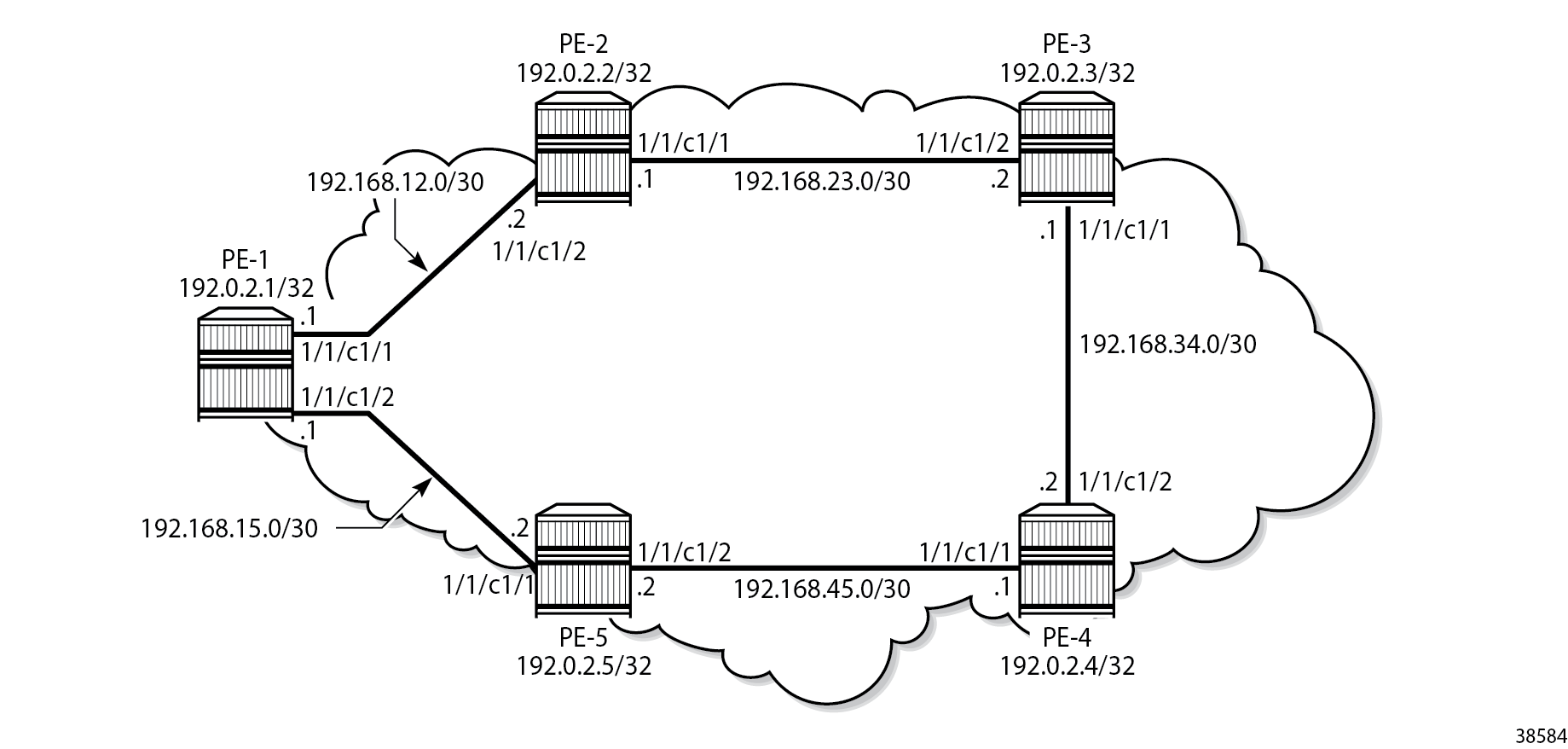
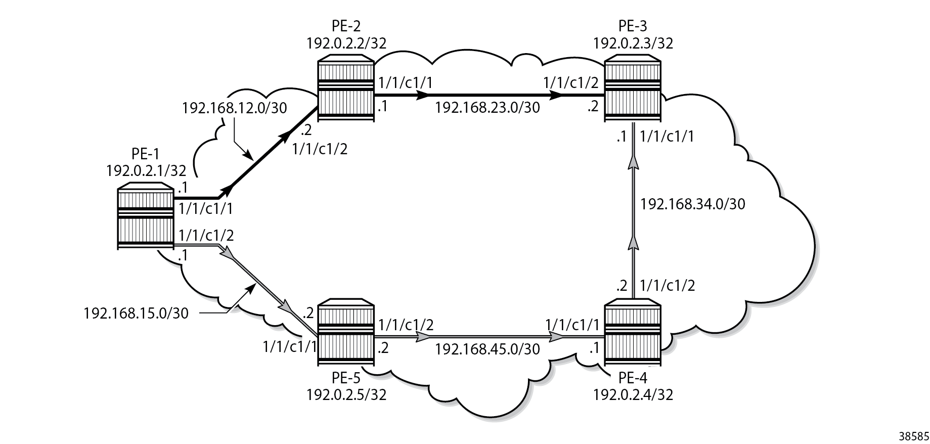
Example topology shows the example topology that contains five 7750 SRs in a ring topology.
Definitions
The following definitions are used in this chapter:
Forwarding Classes (FCs) classify micro-flows into macro-flows. FCs can be mapped to Class Types (CTs).
A CT is macro-flow crossing a link governed by a specific Bandwidth Constraint (BC). The BC is defined on a per-link and per-CT basis. A CT can be considered as a network-wide FC, advertised by the IGP (OSPF opaque link state advertisement (LSA), IS-IS TE Type Length Value (TLV)).
IGP-TE can reserve bandwidth per CT on a link (BC).
RSVP-TE can reserve bandwidth per LSP path, based on TE class.
A TE class is a combination of a CT and a preemption priority.
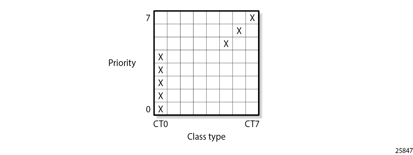
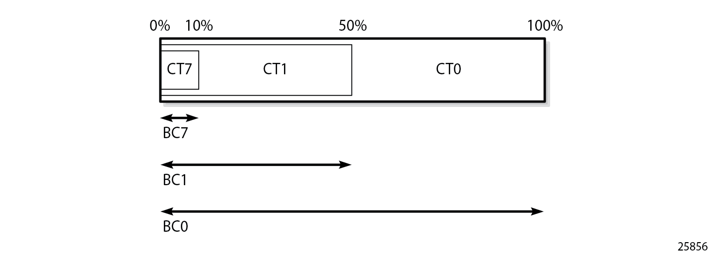
There are eight FCs that can be mapped to CTs. The CTs range from CT0 (lowest) to CT7 (highest) and each gets a percentage of the bandwidth of the link. Each CT has eight different priority levels that are used for preemption. Even though there are 64 different potential combinations of CT and priority, only eight different combinations can be defined for TE classes. All CTs and priorities must be manually configured.
The system allows up to eight TE classes to be configured. The more TE classes are defined, the more RSVP LSPs need to be configured for each service. TE classes are consistently configured on all TE-aware Label Switching Routers (LSRs) throughout the network and advertised through the IGP.
The following shows a DiffServ TE configuration where each CT can reserve up to 10% of the maximum reservable bandwidth meaning that 20% of the bandwidth is not allocated to any CT. MPLS needs to be shut down when DiffServ TE is configured. Mapping of TE classes shows the mapping of the TE classes.
# on PE-1:
configure {
    router "Base" {
        rsvp {
            preemption-timer 5
            diffserv-te {
                admission-control-model mam
                class-type-bw {
                    ct0 10
                    ct1 10
                    ct2 10
                    ct3 10
                    ct4 10
                    ct5 10
                    ct6 10
                    ct7 10
                }
                te-class 0 {
                    class-type 0
                    priority 0
                }
                te-class 1 {
                    class-type 0
                    priority 1
                }
                te-class 2 {
                    class-type 0
                    priority 2
                }
                te-class 3 {
                    class-type 0
                    priority 3
                }
                te-class 4 {
                    class-type 0
                    priority 4
                }
                te-class 5 {
                    class-type 5
                    priority 5
                }
                te-class 6 {
                    class-type 6
                    priority 6
                }
                te-class 7 {
                    class-type 7
                    priority 7
                }
                fc af {
                    class-type 0
                }
                fc be {
                    class-type 0
                }
                fc ef {
                    class-type 5
                }
                fc h1 {
                    class-type 6
                }
                fc h2 {
                    class-type 0
                }
                fc l1 {
                    class-type 0
                }
                fc l2 {
                    class-type 0
                }
                fc nc {
                    class-type 7
                }
            }
This configuration is applied on all TE-aware LSRs for consistency.
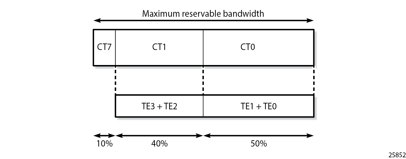
Bandwidth reservation for the CTs shows the bandwidth reservation for the CTs.
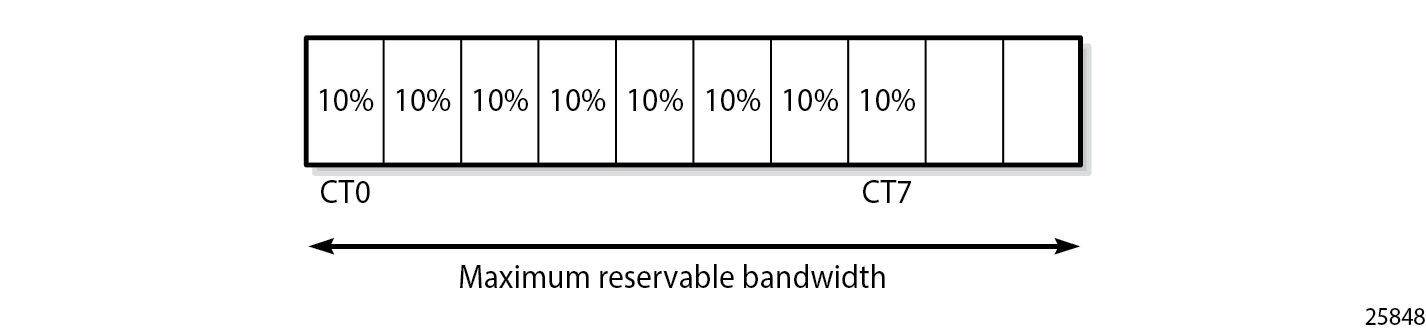
Eight TE classes are defined, each with a different priority, using four CTs (0, 5, 6 and 7). There is no need to assign any bandwidth to the unused CTs. The configuration in this example is not a recommendation. In this example, the BC for each CT is 10% of the maximum reservable bandwidth.
On each node, the RSVP status shows whether DiffServ TE is enabled and how it is configured, as follows:
[/]
A:admin@PE-1# show router rsvp status

===============================================================================
RSVP Status
===============================================================================
Admin Status       : Up                 Oper Status        : Up
Keep Multiplier    : 3                  Refresh Time       : 30 sec
Message Pacing     : Disabled           Pacing Period      : 100 msec
Max Packet Burst   : 650 msgs           Refresh Bypass     : Disabled
Rapid Retransmit   : 5 hmsec            Rapid Retry Limit  : 3
Graceful Shutdown  : Disabled           SoftPreemptionTimer: 5 sec
GR Max Recovery    : 300 sec            GR Max Restart     : 120 sec
Implicit Null Label: Disabled           Node-id in RRO     : Exclude
P2P Merge Point Ab*: Disabled           P2MP Merge Point A*: Disabled
Auth Over Bypass   : Disabled
DiffServTE AdmModel: Mam                Entropy Label      : Disabled
Percent Link Bw CT0: 10                 Percent Link Bw CT4: 10
Percent Link Bw CT1: 10                 Percent Link Bw CT5: 10
Percent Link Bw CT2: 10                 Percent Link Bw CT6: 10
Percent Link Bw CT3: 10                 Percent Link Bw CT7: 10
TE0 -> Class Type  : 0                  Priority           : 0
TE1 -> Class Type  : 0                  Priority           : 1
TE2 -> Class Type  : 0                  Priority           : 2
TE3 -> Class Type  : 0                  Priority           : 3
TE4 -> Class Type  : 0                  Priority           : 4
TE5 -> Class Type  : 5                  Priority           : 5
TE6 -> Class Type  : 6                  Priority           : 6
TE7 -> Class Type  : 7                  Priority           : 7
FCName             : af                 Class Type         : 0
FCName             : be                 Class Type         : 0
FCName             : ef                 Class Type         : 5
FCName             : h1                 Class Type         : 6
FCName             : h2                 Class Type         : 0
FCName             : l1                 Class Type         : 0
FCName             : l2                 Class Type         : 0
FCName             : nc                 Class Type         : 7
IgpThresholdUpdate : Disabled
Up Thresholds(%)   : 0 15 30 45 60 75 80 85 90 95 96 97 98 99 100
Down Thresholds(%) : 100 99 98 97 96 95 90 85 80 75 60 45 30 15 0
Update Timer       : N/A
Update on CAC Fail : Disabled
===============================================================================
* indicates that the corresponding row element may have been truncated.
The OSPF LSAs contain BC information, as shown in the following output taken from PE-1:
[/]
A:admin@PE-1# show router ospf opaque-database adv-router 192.0.2.3 detail

===============================================================================
Rtr Base OSPFv2 Instance 0 Opaque Link State Database (type: All) (detail)
===============================================================================
-------------------------------------------------------------------------------
Opaque LSA
-------------------------------------------------------------------------------
Area Id          : 0.0.0.0              Adv Router Id    : 192.0.2.3
Link State Id    : 1.0.0.1              LSA Type         : Area Opaque
Sequence No      : 0x80000002           Checksum         : 0x9a28
Age              : 232                  Length           : 28
Options          :  E
Advertisement    : Traffic Engineering
     ROUTER-ID TLV  (0001) Len   4 : 192.0.2.3
-------------------------------------------------------------------------------
Opaque LSA
-------------------------------------------------------------------------------
Area Id          : 0.0.0.0              Adv Router Id    : 192.0.2.3
Link State Id    : 1.0.0.2              LSA Type         : Area Opaque
Sequence No      : 0x8000000a           Checksum         : 0xe962
Age              : 57                   Length           : 164
Options          :  E
Advertisement    : Traffic Engineering
     LINK INFO TLV  (0002) Len 140 :
       Sub-TLV: 1     Len: 1     LINK_TYPE    : 1
       Sub-TLV: 2     Len: 4     LINK_ID      : 192.0.2.2
       Sub-TLV: 3     Len: 4     LOC_IP_ADDR  : 192.168.23.2
       Sub-TLV: 4     Len: 4     REM_IP_ADDR  : 192.168.23.1
       Sub-TLV: 5     Len: 4     TE_METRIC    : 10
       Sub-TLV: 6     Len: 4     MAX_BDWTH    : 10000000 Kbps
       Sub-TLV: 7     Len: 4     RSRVBL_BDWTH : 10000000 Kbps
       Sub-TLV: 8     Len: 32    UNRSRVD_CLS0 :
         P0: 1000000 Kbps P1: 1000000 Kbps P2: 1000000 Kbps P3: 1000000 Kbps
         P4: 1000000 Kbps P5: 1000000 Kbps P6: 1000000 Kbps P7: 1000000 Kbps
       Sub-TLV: 9     Len: 4     ADMIN_GROUP  : 0 None
       Sub-TLV: 17    Len: 36    TELK_BW_CONST:
         BW Model : MAM
         BC0: 1000000 Kbps BC1: 1000000 Kbps BC2: 1000000 Kbps BC3: 1000000 Kbps
         BC4: 1000000 Kbps BC5: 1000000 Kbps BC6: 1000000 Kbps BC7: 1000000 Kbps
---snip---
===============================================================================
In the preceding output, only the output for the interface between PE-2 and PE-3 is shown; the output is similar for the other interfaces. On each interface between nodes, there are eight BCs for the eight CTs: from BC0 to BC7. In this example, each of the BCs has the same constraint of 1 Gb/s, which corresponds to 10% of the 10 Gb/s interfaces. As long as no LSP is configured with a CT and a bandwidth, no bandwidth is reserved. The BCs for an interface, such as the interface between PE-1 and PE-2, can be shown as follows:
[/]
A:admin@PE-1# show router rsvp interface "int-PE-1-PE-2" detail

===============================================================================
RSVP Interface (Detailed) : int-PE-1-PE-2
===============================================================================
-------------------------------------------------------------------------------
Interface : int-PE-1-PE-2
-------------------------------------------------------------------------------
Interface         : int-PE-1-PE-2
Port ID           : 1/1/c1/1
Admin State       : Up                  Oper State        : Up
Active Sessions   : 0                   Active Resvs      : 0
Total Sessions    : 0
Subscription      : 100 %               Port Speed        : 10000 Mbps
Total BW          : 10000 Mbps          Aggregate         : Dsabl
Hello Interval    : 3000 ms             Hello Timeouts    : 0
Key Type Auth     : Disabled
Keychain Auth     : Disabled
Auth Rx Seq Num   : n/a                 Auth Key Id       : n/a
Auth Tx Seq Num   : n/a                 Auth Win Size     : n/a
Refresh Reduc.    : Disabled            Reliable Deli.    : Disabled
Bfd Enabled       : No                  Graceful Shut.    : Disabled
ImplicitNullLabel : Disabled*           GR helper         : Disabled

Percent Link Bandwidth for Class Types*
Link Bw CT0       : 10                  Link Bw CT4       : 10
Link Bw CT1       : 10                  Link Bw CT5       : 10
Link Bw CT2       : 10                  Link Bw CT6       : 10
Link Bw CT3       : 10                  Link Bw CT7       : 10

Bandwidth Constraints for Class Types (Kbps)
BC0               : 1000000             BC4               : 1000000
BC1               : 1000000             BC5               : 1000000
BC2               : 1000000             BC6               : 1000000
BC3               : 1000000             BC7               : 1000000

Bandwidth for TE Class Types (Kbps)
TE0->  Resv. Bw   : 0                   Unresv. Bw        : 1000000
TE1->  Resv. Bw   : 0                   Unresv. Bw        : 1000000
TE2->  Resv. Bw   : 0                   Unresv. Bw        : 1000000
TE3->  Resv. Bw   : 0                   Unresv. Bw        : 1000000
TE4->  Resv. Bw   : 0                   Unresv. Bw        : 1000000
TE5->  Resv. Bw   : 0                   Unresv. Bw        : 1000000
TE6->  Resv. Bw   : 0                   Unresv. Bw        : 1000000
TE7->  Resv. Bw   : 0                   Unresv. Bw        : 1000000

IGP Update
Up Thresholds(%)   : 0 15 30 45 60 75 80 85 90 95 96 97 98 99 100  *
Down Thresholds(%) : 100 99 98 97 96 95 90 85 80 75 60 45 30 15 0  *
IGP Update Pending : No
Next Update        : N/A

No Neighbors.
* indicates inherited values
===============================================================================
In this example, all BCs for the CTs are equal to 1 Gb/s, which is 10% of the maximum reservable bandwidth of 10 Gb/s. Currently no bandwidth is reserved for any of the TE classes. The unreserved bandwidth equals 1 Gb/s for TE0 through TE7.
The maximum bandwidth that can be allocated depends on the bandwidth of the link and the subscription percentage. When the subscription percentage is doubled to 200%, the BCs are doubled too, as follows:
# on PE-1:
configure {
    router "Base" {
        rsvp {
            interface "int-PE-1-PE-2" {
                subscription 200
            }
[/]
A:admin@PE-1# show router rsvp interface "int-PE-1-PE-2" detail

===============================================================================
RSVP Interface (Detailed) : int-PE-1-PE-2
===============================================================================
-------------------------------------------------------------------------------
Interface : int-PE-1-PE-2
-------------------------------------------------------------------------------
---snip---
Percent Link Bandwidth for Class Types*
Link Bw CT0       : 10                  Link Bw CT4       : 10
Link Bw CT1       : 10                  Link Bw CT5       : 10
Link Bw CT2       : 10                  Link Bw CT6       : 10
Link Bw CT3       : 10                  Link Bw CT7       : 10

Bandwidth Constraints for Class Types (Kbps)
BC0               : 2000000             BC4               : 2000000
BC1               : 2000000             BC5               : 2000000
BC2               : 2000000             BC6               : 2000000
BC3               : 2000000             BC7               : 2000000

Bandwidth for TE Class Types (Kbps)
TE0->  Resv. Bw   : 0                   Unresv. Bw        : 2000000
TE1->  Resv. Bw   : 0                   Unresv. Bw        : 2000000
TE2->  Resv. Bw   : 0                   Unresv. Bw        : 2000000
TE3->  Resv. Bw   : 0                   Unresv. Bw        : 2000000
TE4->  Resv. Bw   : 0                   Unresv. Bw        : 2000000
TE5->  Resv. Bw   : 0                   Unresv. Bw        : 2000000
TE6->  Resv. Bw   : 0                   Unresv. Bw        : 2000000
TE7->  Resv. Bw   : 0                   Unresv. Bw        : 2000000
---snip---
===============================================================================
The subscription percentage is restored to its default value of 100% as follows:
# on PE-1:
configure {
    router "Base" {
        rsvp {
            interface "int-PE-1-PE-2" {
                delete subscription
            }
Bandwidth constraint models
Two models are available for the bandwidth calculation that is required during the LSP setup: the Maximum Allocation Model (MAM) and the Russian Doll Model (RDM). Comparison bandwidth constraint models shows a comparison between the two models.
Maximum Allocation Model (MAM) |
Russian Doll Model (RDM) |
|---|---|
Fixed BC per CT. No bandwidth sharing between CTs. |
Maps one BC to one or more CTs. Lower CTs are allowed to reserve from the unused bandwidth of the pools defined for higher CTs. |
Achieves isolation between CTs and guaranteed bandwidth to CTs without the need for preemption. |
No isolation between CTs. Requires preemption to guarantee bandwidth to CTs other than the premium. |
Bandwidth may be wasted. |
Efficient use of bandwidth. |
Easy to manage. |
More complex. |
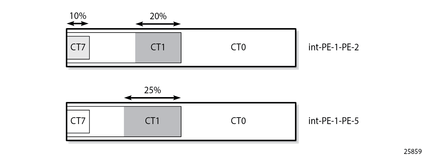
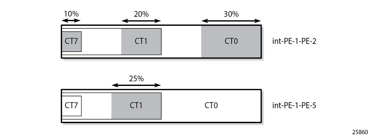
Bandwidth reservation in Maximum Allocation Model for three CTs shows the reserved bandwidth for the different class types according to the MAM model. In this example, there is only bandwidth reserved for CT0, CT1, and CT2.

Bandwidth that is reserved for a specific CT cannot be used by any other CT. Therefore, bandwidth may be wasted.
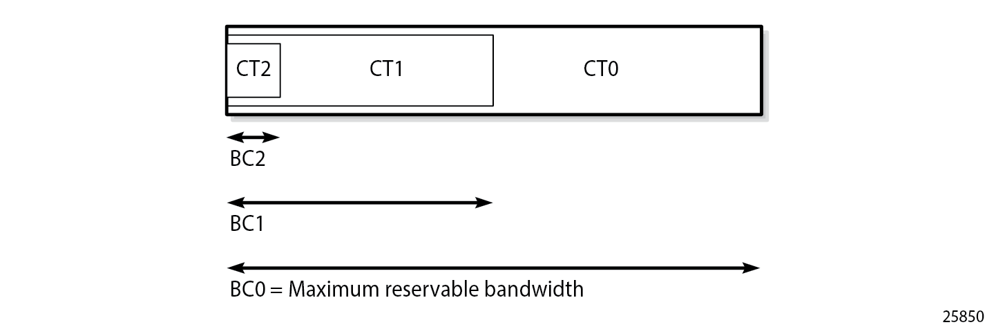
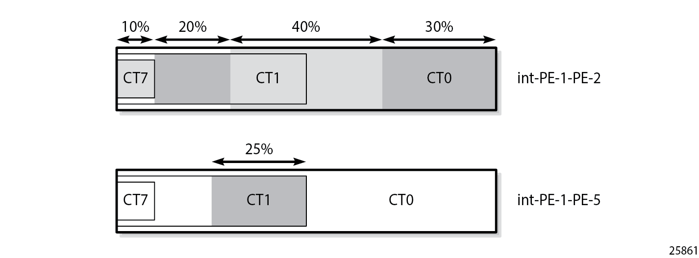
The Russian Doll Model is more flexible: when CT1 has some spare bandwidth that may be used by CT0, this is allowed. Depending on the configured setup priority and hold priority, this may be reversed when CT1 requires the bandwidth. The bandwidth reservation in the Russian Doll Model is shown in Bandwidth reservation in Russian Doll Model for three CTs.
Backup class types
The main CT is defined at LSP level or primary path level. The main CT is used at the first attempt for the initial establishment and re-signal Make-Before-Break (MBB) of the LSP primary path. Re-signaling of the LSP path can be triggered manually or timer-based. Subsequent retries use the backup CT, which is configured on the primary path level. Secondary paths are always signaled with the main CT. There is no verification whether the backup CT is lower than the main CT. This applies to CSPF and non-CSPF LSPs. An example of an LSP with main CT1 and backup CT0 is as follows:
# on PE-1:
configure {
    router "Base" {
        mpls {
            path "dyn" {
                admin-state enable
            }
            lsp "LSP-PE-1-PE-3-withBackupCT" {
                admin-state enable
                type p2p-rsvp
                to 192.0.2.3
                path-computation-method local-cspf
                class-type 1
                primary "dyn" {
                    bandwidth 50
                    backup-class-type 0
                    priority {
                        setup-priority 4
                        hold-priority 4
                    }
                }
            }
Possible triggers for using the backup CT are:
Local interface failure or control plane failure (hello timeout)
Received Resv message with the local-protection-in-use flag set (global revertive trigger)
Received Patherr message with Fast ReRoute (FRR) protection active notification (global revertive trigger)
Received Patherr message with error code 34 (Reroute) and value 1 (soft preemption trigger)
Received Patherr message with Preemption pending flag set (soft preemption trigger)
Received ResvTear message
When the reservable bandwidth for a CT (including the bandwidth for the inner dolls in case of RDM) is insufficient, this does not trigger the backup CT to be used. If possible, an alternate path is used for the LSP requiring this bandwidth.
Priorities
Two different priorities are linked to an LSP in a range from 0 to 7, where 0 is the highest priority and 7 the lowest. These values are important when preemption occurs, as follows:
# on PE-1:
A:admin@:PE-1# configure {
    router "Base" {
        mpls {
            lsp "LSP-PE-1-PE-3" {
                primary "dyn" {
                    priority ?

 priority

 hold-priority         - Priority of an LSP session at preemption action
 setup-priority        - Priority when insufficient bandwidth for LSP setup

where:
 hold-priority <number>
 <number> - <0..7>
 Default  - 0
and
 setup-priority <number>
 <number> - <0..7>
 Default  - 7
The following shows an LSP with both priorities equal to 4:
# on PE-1:
configure {
    router "Base" {
        mpls {
            lsp "LSP-PE-1-PE-3" {
                admin-state enable
                type p2p-rsvp
                to 192.0.2.3
                path-computation-method local-cspf
                primary "dyn" {
                    bandwidth 50
                    priority {
                        setup-priority 4
                        hold-priority 4
                    }
The first priority in the configuration is the setup priority. When an LSP is signaled and there is not enough bandwidth available on the egress Label Edge Router (eLER) or LSR, the LSP can preempt an established LSP with a hold priority lower than this setup priority. For a setup priority of 4, existing LSPs with a hold priority of 5, 6, or 7 can be preempted in case of insufficient bandwidth.
The second priority in the configuration is the hold priority. When this LSP is established and a new LSP needs to be established, and there is insufficient bandwidth, this LSP can only be preempted by an LSP with a higher setup priority than this hold priority. For a hold priority of 4, the LSP can be preempted by any LSP with a setup priority of 0, 1, 2, or 3.
The default values are a setup priority of 7 and a hold priority of 0. A low setup priority of 7 means the LSP cannot preempt any LSP. A high hold priority of 0 implies that the LSP cannot be preempted by any other LSP.
The setup priority needs to be lower than or equal to the hold priority to avoid preemption loops. Nokia recommends that the setup priority and the hold priority are set to equal values.
Bandwidth, CT information, and priorities are shown as follows:
[/]
A:admin@PE-1# show router mpls lsp "LSP-PE-1-PE-3" path detail

===============================================================================
MPLS LSP LSP-PE-1-PE-3 Path  (Detail)
===============================================================================
Legend :
    @ - Detour Available              # - Detour In Use
    b - Bandwidth Protected           n - Node Protected
    s - Soft Preemption
    S - Strict                        L - Loose
    A - ABR                           + - Inherited
===============================================================================
-------------------------------------------------------------------------------
LSP LSP-PE-1-PE-3
Path dyn
-------------------------------------------------------------------------------
LSP Name    : LSP-PE-1-PE-3
From             : 192.0.2.1
To               : 192.0.2.3
Admin State      : Up                      Oper State        : Up
Path Name   : dyn
Path LSP ID      : 43008                   Path Type         : Primary
Path Admin       : Up                      Path Oper         : Up
Out Interface    : 1/1/c1/1                Out Label         : 524287
---snip---
Neg MTU          : 1564                    Oper MTU          : 1564
Bandwidth        : 50 Mbps                 Oper Bandwidth    : 50 Mbps
Hop Limit        : 255                     Oper HopLimit     : 255
Record Route     : Record                  Oper Record Route : Record
Record Label     : Record                  Oper Record Label : Record
Setup Priority   : 4                       Oper SetupPriority: 4
Hold Priority    : 4                       Oper HoldPriority : 4
Class Type       : 0                       Oper CT           : 0
Backup CT        : None
MainCT Retry     : n/a
    Rem          :
MainCT Retry     : 0
    Limit        :
---snip---
===============================================================================
When the LSP is being established, the path message contains the setup and hold priorities, and the required bandwidth, as follows:
# on PE-1:
debug
    router
        rsvp
            packet
                path detail
            exit
1 2023/04/12 21:29:24.744 CEST MINOR: DEBUG #2001 Base RSVP
"RSVP: PATH Msg
Send PATH From:192.0.2.1, To:192.0.2.3
          TTL:255, Checksum:0xe791, Flags:0x0
Session    - EndPt:192.0.2.3, TunnId:2, ExtTunnId:192.0.2.1
SessAttr   - Name:LSP-PE-1-PE-3::dyn
             SetupPri:4, HoldPri:4, Flags:0x46
RSVPHop    - Ctype:1, Addr:192.168.12.1, LIH:2
TimeValue  - RefreshPeriod:30
SendTempl  - Sender:192.0.2.1, LspId:43008
SendTSpec  - Ctype:QOS, CDR:50.000 Mbps, PBS:50.000 Mbps, PDR:infinity
             MPU:20, MTU:1564
LabelReq   - IfType:General, L3ProtID:2048
RRO        - IpAddr:192.168.12.1, Flags:0x0
ERO        - IPv4Prefix 192.168.12.2/32, Strict
             IPv4Prefix 192.168.23.2/32, Strict
"
As soon as the LSP is established, the bandwidth is reserved on the interface int-PE-1-PE-2 on PE-1 in TE class 4 (configured as a combination of CT0 and priority 4), as follows:
[/]
A:admin@PE-1# show router rsvp interface "int-PE-1-PE-2" detail

===============================================================================
RSVP Interface (Detailed) : int-PE-1-PE-2
===============================================================================
-------------------------------------------------------------------------------
Interface : int-PE-1-PE-2
-------------------------------------------------------------------------------
Interface         : int-PE-1-PE-2
Port ID           : 1/1/c1/1
Admin State       : Up                  Oper State        : Up
Active Sessions   : 1                   Active Resvs      : 1
Total Sessions    : 1
Subscription      : 100 %               Port Speed        : 10000 Mbps
Total BW          : 10000 Mbps          Aggregate         : Dsabl
---snip---
Percent Link Bandwidth for Class Types*
Link Bw CT0       : 10                  Link Bw CT4       : 10
Link Bw CT1       : 10                  Link Bw CT5       : 10
Link Bw CT2       : 10                  Link Bw CT6       : 10
Link Bw CT3       : 10                  Link Bw CT7       : 10

Bandwidth Constraints for Class Types (Kbps)
BC0               : 1000000             BC4               : 1000000
BC1               : 1000000             BC5               : 1000000
BC2               : 1000000             BC6               : 1000000
BC3               : 1000000             BC7               : 1000000

Bandwidth for TE Class Types (Kbps)
TE0->  Resv. Bw   : 0                   Unresv. Bw        : 1000000
TE1->  Resv. Bw   : 0                   Unresv. Bw        : 1000000
TE2->  Resv. Bw   : 0                   Unresv. Bw        : 1000000
TE3->  Resv. Bw   : 0                   Unresv. Bw        : 1000000
TE4->  Resv. Bw   : 50000               Unresv. Bw        : 950000
TE5->  Resv. Bw   : 0                   Unresv. Bw        : 1000000
TE6->  Resv. Bw   : 0                   Unresv. Bw        : 1000000
TE7->  Resv. Bw   : 0                   Unresv. Bw        : 1000000
---snip---
===============================================================================
Configuration
The example topology consists of five 7750 SRs in a ring topology, as shown in Example topology.
Initial Configuration
The nodes have the following initial configuration:
Cards, MDAs, ports
Router interfaces. For PE-1:
# on PE-1:
configure {
    router "Base" {
        interface "int-PE-1-PE-2" {
            port 1/1/c1/1
            ipv4 {
                primary {
                    address 192.168.12.1
                    prefix-length 30
                }
            }
        }
        interface "int-PE-1-PE-5" {
            port 1/1/c1/2
            ipv4 {
                primary {
                    address 192.168.15.1
                    prefix-length 30
                }
            }
        }
        interface "system" {
            ipv4 {
                primary {
                    address 192.0.2.1
                    prefix-length 32
                }
            }
        }
IGP: OSPF (alternatively, IS-IS could have been used) with TE enabled. For PE-1:
# on PE-1:
configure {
    router "Base" {
        ospf 0 {
            admin-state enable
            traffic-engineering true
            area 0.0.0.0 {
                interface "int-PE-1-PE-2" {
                    interface-type point-to-point
                }
                interface "int-PE-1-PE-5" {
                    interface-type point-to-point
                }
                interface "system" {
                }
            }
        }
MPLS and RSVP enabled on all interfaces. For PE-1:
# on PE-1:
configure {
    router "Base" {
        mpls {
            admin-state enable
            interface "int-PE-1-PE-2" {
            }
            interface "int-PE-1-PE-5" {
            }
        }
        rsvp {
            admin-state enable
            interface "int-PE-1-PE-2" {
            }
            interface "int-PE-1-PE-5" {
            }
        }
LSPs are established from PE-1 to PE-3 with the short path via PE-2 as preferred. If insufficient bandwidth is available on the short path via PE-2, the longer path via PE-5 and PE-4 is taken, as shown in Paths from PE-1 to PE-3.
Initially, the default BC model, which is MAM, is enabled. Different LSPs are created with different class type and priority. When an LSP is established, the bandwidth reservation is verified on the interfaces of PE-1. The same LSPs are later established for the second BC model, RDM, where the bandwidth reservation is more efficient. For simplicity, FRR is not enabled on the LSPs.
Maximum Allocation Model
Enable DiffServ MAM
The DiffServ TE configuration must be consistent on all the nodes in the setup. In this example, DiffServ TE is configured as follows:
# on PE-1:
configure {
    router "Base" {
        rsvp {
            diffserv-te {
                admission-control-model mam
                class-type-bw {
                    ct0 50
                    ct1 40
                    ct7 10
                }
                te-class 0 {
                    class-type 0
                    priority 7
                }
                te-class 1 {
                    class-type 0
                    priority 4
                }
                te-class 2 {
                    class-type 1
                    priority 7
                }
                te-class 3 {
                    class-type 1
                    priority 4
                }
                te-class 4 {
                    class-type 2
                    priority 7
                }
                te-class 5 {
                    class-type 2
                    priority 2
                }
                fc af {
                    class-type 1
                }
                fc be {
                    class-type 0
                }
                fc nc {
                    class-type 2
                }
            }
The sum of bandwidth percentages can be lower than, but must not exceed 100%, as follows:
A:admin@PE-1# configure {
    router "Base" {
        rsvp {
            diffserv-te {
                admission-control-model mam
                class-type-bw {
                    ct0 50
                    ct1 50
                    ct7 10
                }
MINOR: RSVP #1005: configure router "Base" rsvp diffserv-te class-type-bw ct0 - Invalid operation for RSVP instance - Total CT percent exceeds 100
Fewer than eight classes can be configured, as in this example.
In the example, only three CTs are used by the TE classes: CT0, CT1, and CT2. However, 10% of the maximum reservable bandwidth is allocated to CT7. Because the MAM model does not allow bandwidth allocated to a CT to be used by other CTs, only 90% of the bandwidth can be reserved: 50% to be divided between TE0 and TE1, and 40% to be divided between TE2 and TE3. TE4 and TE5 do not have any bandwidth allocated. The bandwidth allocated to CT7 is completely wasted. This is just an example, not a recommendation.
The same settings are repeated in the RDM model, where the bandwidth is not wasted. The following bandwidth information can be seen on any interface:
[/]
A:admin@PE-1# show router rsvp interface "int-PE-1-PE-2" detail

===============================================================================
RSVP Interface (Detailed) : int-PE-1-PE-2
===============================================================================
-------------------------------------------------------------------------------
Interface : int-PE-1-PE-2
-------------------------------------------------------------------------------
---snip---
Percent Link Bandwidth for Class Types*
Link Bw CT0       : 50                  Link Bw CT4       : 0
Link Bw CT1       : 40                  Link Bw CT5       : 0
Link Bw CT2       : 0                   Link Bw CT6       : 0
Link Bw CT3       : 0                   Link Bw CT7       : 10

Bandwidth Constraints for Class Types (Kbps)
BC0               : 5000000             BC4               : 0
BC1               : 4000000             BC5               : 0
BC2               : 0                   BC6               : 0
BC3               : 0                   BC7               : 1000000

Bandwidth for TE Class Types (Kbps)
TE0->  Resv. Bw   : 0                   Unresv. Bw        : 5000000
TE1->  Resv. Bw   : 0                   Unresv. Bw        : 5000000
TE2->  Resv. Bw   : 0                   Unresv. Bw        : 4000000
TE3->  Resv. Bw   : 0                   Unresv. Bw        : 4000000
TE4->  Resv. Bw   : 0                   Unresv. Bw        : 0
TE5->  Resv. Bw   : 0                   Unresv. Bw        : 0
TE6->  Resv. Bw   : 0                   Unresv. Bw        : 0
TE7->  Resv. Bw   : 0                   Unresv. Bw        : 0
---snip---
===============================================================================
MAM bandwidth allocation shows the bandwidth allocation for the CTs and TE classes.
Establishing LSPs
TE class 5 corresponds to CT2 and priority 2. No bandwidth can be reserved for an RSVP LSP with CT2, setup priority 2, and hold priority 2. This can be verified by configuring an empty path and an LSP, as follows:
# on PE-1:
configure {
    router "Base" {
        mpls {
            path "dyn" {
                admin-state enable
            }
            lsp "LSP-PE-1-PE-3-TE5" {
                admin-state enable
                type p2p-rsvp
                to 192.0.2.3
                class-type 2
                path-computation-method local-cspf
                primary "dyn" {
                    bandwidth 1000
                    priority {
                        setup-priority 2
                        hold-priority 2
                    }
The path computation method must be local CSPF. The class type is by default CT0, but can be changed to CT2 by configuration. The class type can be configured in the lsp context, as shown here, or in the primary path context. The setup priority and hold priority are configured in the primary path context.
The LSP cannot be established, because no bandwidth is allocated to TE class 5, as follows:
[/]
A:admin@PE-1# show router mpls lsp "LSP-PE-1-PE-3-TE5" path detail | match "Failure Code"
Failure Code     : noCspfRouteToDestination
No bandwidth is reserved on the RSVP interfaces, as follows:
[/]
A:admin@PE-1# show router rsvp interface

===============================================================================
RSVP Interfaces
===============================================================================
Interface                        Total    Active    Total BW  Resv BW   Adm Opr
                                 Sessions Sessions  (Mbps)    (Mbps)
-------------------------------------------------------------------------------
system                           -        -         -         -         Up  Up
int-PE-1-PE-2                    0        0         10000     0         Up  Up
int-PE-1-PE-5                    0        0         10000     0         Up  Up
-------------------------------------------------------------------------------
Interfaces : 3
===============================================================================
Bandwidth can be reserved for an LSP with CT1 and priorities 4, as for the following LSP:
# on PE-1:
configure {
    router "Base" {
        mpls {
            lsp "LSP-PE-1-PE-3-TE3" {
                admin-state enable
                type p2p-rsvp
                to 192.0.2.3
                path-computation-method local-cspf
                primary "dyn" {
                    bandwidth 2000
                    class-type 1
                    priority {
                        setup-priority 4
                        hold-priority 4
                    }
In the example, the CT is configured in the primary path context whereas the CT in the previous example was configured in the lsp context.
The path is set up via PE-2 to PE-3, as follows:
[/]
A:admin@PE-1# show router mpls lsp "LSP-PE-1-PE-3-TE3" path detail

===============================================================================
MPLS LSP LSP-PE-1-PE-3-TE3 Path  (Detail)
===============================================================================
Legend :
    @ - Detour Available              # - Detour In Use
    b - Bandwidth Protected           n - Node Protected
    s - Soft Preemption
    S - Strict                        L - Loose
    A - ABR                           + - Inherited
===============================================================================
-------------------------------------------------------------------------------
LSP LSP-PE-1-PE-3-TE3
Path dyn
-------------------------------------------------------------------------------
LSP Name    : LSP-PE-1-PE-3-TE3
From             : 192.0.2.1
To               : 192.0.2.3
Admin State      : Up                      Oper State        : Up
Path Name   : dyn
Path LSP ID      : 55296                   Path Type         : Primary
Path Admin       : Up                      Path Oper         : Up
Out Interface    : 1/1/c1/1                Out Label         : 524287
---snip---
Actual Hops      :
    192.168.12.1(192.0.2.1)                      Record Label        : N/A
 -> 192.168.12.2(192.0.2.2)                      Record Label        : 524287
 -> 192.168.23.2(192.0.2.3)                      Record Label        : 524287
---snip---
===============================================================================
Bandwidth is reserved in TE class 3, as follows:
[/]
A:admin@PE-1# show router rsvp interface "int-PE-1-PE-2" detail

===============================================================================
RSVP Interface (Detailed) : int-PE-1-PE-2
===============================================================================
-------------------------------------------------------------------------------
Interface : int-PE-1-PE-2
-------------------------------------------------------------------------------
---snip---
Bandwidth for TE Class Types (Kbps)
TE0->  Resv. Bw   : 0                   Unresv. Bw        : 5000000
TE1->  Resv. Bw   : 0                   Unresv. Bw        : 5000000
TE2->  Resv. Bw   : 0                   Unresv. Bw        : 2000000
TE3->  Resv. Bw   : 2000000             Unresv. Bw        : 2000000
TE4->  Resv. Bw   : 0                   Unresv. Bw        : 0
TE5->  Resv. Bw   : 0                   Unresv. Bw        : 0
TE6->  Resv. Bw   : 0                   Unresv. Bw        : 0
TE7->  Resv. Bw   : 0                   Unresv. Bw        : 0
---snip---
===============================================================================
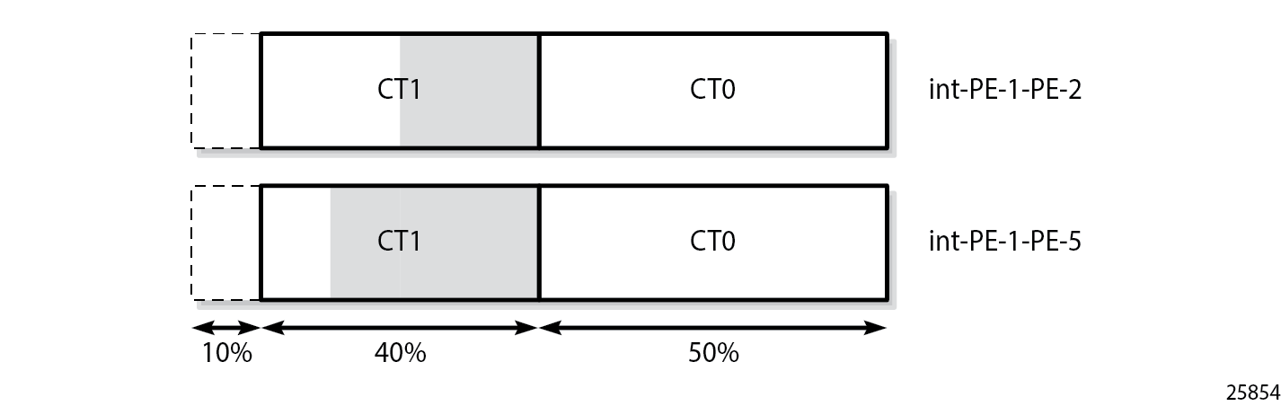
Reserved and unreserved bandwidth shows the bandwidth reservation for CT1 on interface int-PE-1-PE-2 on PE-1 and on interface int-PE-2-PE-3 on PE-2.

An additional LSP is configured with CT1 and priority 4 and with CT0 as backup CT. The backup CT is not used when the amount of unreserved bandwidth for CT1 is insufficient, as in the following case where int-PE-1-PE-2 and int-PE-1-PE-5 have insufficient unreserved bandwidth for CT1:
# on PE-1:
configure {
    router "Base" {
        mpls {
            lsp "LSP-PE-1-PE-3-TE3-backupTE1" {
                admin-state enable
                type p2p-rsvp
                to 192.0.2.3
                path-computation-method local-cspf
                primary "dyn" {
                    bandwidth 5000
                    class-type 1
                    backup-class-type 0
                    priority {
                        setup-priority 4
                        hold-priority 4
                    }
The LSP does not come up, as follows:
[/]
A:admin@PE-1# show router mpls lsp

===============================================================================
MPLS LSPs (Originating)
===============================================================================
LSP Name                                            Tun     Fastfail  Adm  Opr
  To                                                Id      Config
-------------------------------------------------------------------------------
LSP-PE-1-PE-3-TE5                                   3       No        Up   Dwn
  192.0.2.3
LSP-PE-1-PE-3-TE3                                   4       No        Up   Up
  192.0.2.3
LSP-PE-1-PE-3-TE3-backupTE1                         5       No        Up   Dwn
  192.0.2.3
-------------------------------------------------------------------------------
LSPs : 3
===============================================================================
The bandwidth requirement is lowered, as follows:
# on PE-1:
configure {
    router "Base" {
        mpls {
            lsp "LSP-PE-1-PE-3-TE3-backupTE1" {
                primary "dyn" {
                    bandwidth 2500
                }
            }
Interface int-PE-1-PE-2 does not have sufficient bandwidth for CT1, but the longer path via PE-5 and PE-4 has sufficient unreserved bandwidth for CT1. The LSP is operationally up, as follows:
[/]
A:admin@PE-1# show router mpls lsp "LSP-PE-1-PE-3-TE3-backupTE1" path detail

===============================================================================
MPLS LSP LSP-PE-1-PE-3-TE3-backupTE1 Path  (Detail)
===============================================================================
Legend :
    @ - Detour Available              # - Detour In Use
    b - Bandwidth Protected           n - Node Protected
    s - Soft Preemption
    S - Strict                        L - Loose
    A - ABR                           + - Inherited
===============================================================================
-------------------------------------------------------------------------------
LSP LSP-PE-1-PE-3-TE3-backupTE1
Path dyn
-------------------------------------------------------------------------------
LSP Name    : LSP-PE-1-PE-3-TE3-backupTE1
From             : 192.0.2.1
To               : 192.0.2.3
Admin State      : Up                      Oper State        : Up
Path Name   : dyn
Path LSP ID      : 32256                   Path Type         : Primary
Path Admin       : Up                      Path Oper         : Up
Out Interface    : 1/1/c1/2                Out Label         : 524287
---snip---
Setup Priority   : 4                       Oper SetupPriority: 4
Hold Priority    : 4                       Oper HoldPriority : 4
Class Type       : 1                       Oper CT           : 1
Backup CT        : 0
---snip---
Actual Hops      :
    192.168.15.1(192.0.2.1)                      Record Label        : N/A
 -> 192.168.15.2(192.0.2.5)                      Record Label        : 524287
 -> 192.168.45.1(192.0.2.4)                      Record Label        : 524287
 -> 192.168.34.1(192.0.2.3)                      Record Label        : 524286
---snip---
===============================================================================
The bandwidth reservation on RSVP interface int-PE-1-PE-2 remains unchanged, because the bandwidth is reserved on int-PE-1-PE-5, as follows:
[/]
A:admin@PE-1# show router rsvp interface "int-PE-1-PE-5" detail

===============================================================================
RSVP Interface (Detailed) : int-PE-1-PE-5
===============================================================================
-------------------------------------------------------------------------------
Interface : int-PE-1-PE-5
-------------------------------------------------------------------------------
Interface         : int-PE-1-PE-5
Port ID           : 1/1/c1/2
---snip---
Percent Link Bandwidth for Class Types*
Link Bw CT0       : 50                  Link Bw CT4       : 0
Link Bw CT1       : 40                  Link Bw CT5       : 0
Link Bw CT2       : 0                   Link Bw CT6       : 0
Link Bw CT3       : 0                   Link Bw CT7       : 10

Bandwidth Constraints for Class Types (Kbps)
BC0               : 5000000             BC4               : 0
BC1               : 4000000             BC5               : 0
BC2               : 0                   BC6               : 0
BC3               : 0                   BC7               : 1000000

Bandwidth for TE Class Types (Kbps)
TE0->  Resv. Bw   : 0                   Unresv. Bw        : 5000000
TE1->  Resv. Bw   : 0                   Unresv. Bw        : 5000000
TE2->  Resv. Bw   : 0                   Unresv. Bw        : 1500000
TE3->  Resv. Bw   : 2500000             Unresv. Bw        : 1500000
TE4->  Resv. Bw   : 0                   Unresv. Bw        : 0
TE5->  Resv. Bw   : 0                   Unresv. Bw        : 0
TE6->  Resv. Bw   : 0                   Unresv. Bw        : 0
TE7->  Resv. Bw   : 0                   Unresv. Bw        : 0
---snip---
===============================================================================
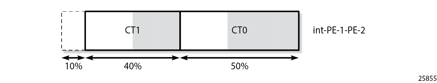
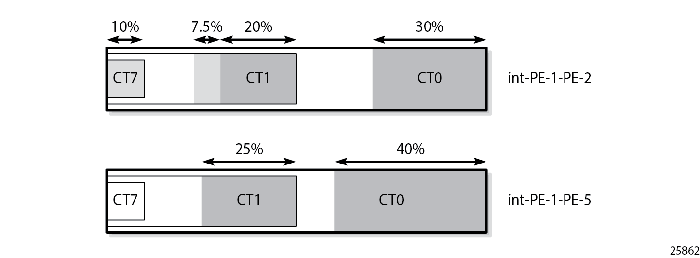
Reserved and unreserved bandwidth on PE-1 shows the reserved and unreserved bandwidth on the RSVP interfaces on PE-1.
Trigger backup class-type
This mechanism is described for MAM, but it is also supported in RDM.
On PE-1, port 1/1/c1/2 is shut down. The long path via PE-5 and PE-4 can no longer be used. However, the LSP has a backup CT (CT0), which is triggered by the port being down, as follows:
# on PE-1:
configure {
    port 1/1/c1/2 {
        admin-state disable
    }
[/]
A:admin@PE-1# show router mpls lsp "LSP-PE-1-PE-3-TE3-backupTE1" path detail

===============================================================================
MPLS LSP LSP-PE-1-PE-3-TE3-backupTE1 Path  (Detail)
===============================================================================
Legend :
    @ - Detour Available              # - Detour In Use
    b - Bandwidth Protected           n - Node Protected
    s - Soft Preemption
    S - Strict                        L - Loose
    A - ABR                           + - Inherited
===============================================================================
-------------------------------------------------------------------------------
LSP LSP-PE-1-PE-3-TE3-backupTE1
Path dyn
-------------------------------------------------------------------------------
LSP Name    : LSP-PE-1-PE-3-TE3-backupTE1
From             : 192.0.2.1
To               : 192.0.2.3
Admin State      : Up                      Oper State        : Up
Path Name   : dyn
Path LSP ID      : 32258                   Path Type         : Primary
Path Admin       : Up                      Path Oper         : Up
Out Interface    : 1/1/c1/1                Out Label         : 524286
---snip---
Setup Priority   : 4                       Oper SetupPriority: 4
Hold Priority    : 4                       Oper HoldPriority : 4
Class Type       : 1                       Oper CT           : 0
Backup CT        : 0
---snip---
Actual Hops      :
    192.168.12.1(192.0.2.1)                      Record Label        : N/A
 -> 192.168.12.2(192.0.2.2)                      Record Label        : 524286
 -> 192.168.23.2(192.0.2.3)                      Record Label        : 524286
---snip---
===============================================================================
The bandwidth for this LSP is reserved in TE class 1, as follows:
[/]
A:admin@PE-1# show router rsvp interface "int-PE-1-PE-2" detail

===============================================================================
RSVP Interface (Detailed) : int-PE-1-PE-2
===============================================================================
-------------------------------------------------------------------------------
Interface : int-PE-1-PE-2
-------------------------------------------------------------------------------
Interface         : int-PE-1-PE-2
Port ID           : 1/1/c1/1
Admin State       : Up                  Oper State        : Up
Active Sessions   : 2                   Active Resvs      : 2
Total Sessions    : 2
---snip---
Bandwidth for TE Class Types (Kbps)
TE0->  Resv. Bw   : 0                   Unresv. Bw        : 2500000
TE1->  Resv. Bw   : 2500000             Unresv. Bw        : 2500000
TE2->  Resv. Bw   : 0                   Unresv. Bw        : 2000000
TE3->  Resv. Bw   : 2000000             Unresv. Bw        : 2000000
TE4->  Resv. Bw   : 0                   Unresv. Bw        : 0
TE5->  Resv. Bw   : 0                   Unresv. Bw        : 0
TE6->  Resv. Bw   : 0                   Unresv. Bw        : 0
TE7->  Resv. Bw   : 0                   Unresv. Bw        : 0
---snip---
===============================================================================
Bandwidth reservation shows the bandwidth reservation on interface int-PE-1-PE-2. The bandwidth reservation on interface int-PE-2-PE-3 on PE-2 is identical.
The preceding examples illustrate that bandwidth can be wasted in the MAM model. The bandwidth allocated to CT7 cannot be used because there is no TE class configured with CT7. The bandwidth cannot be shared between CTs. The next section describes how the same LSPs are used in the RDM model. They are established one-by-one and, therefore, they are shut down, as follows:
# on PE-1:
configure {
    port 1/1/c1/2 {
        admin-state enable
    }
    router "Base" {
        mpls {
            lsp "LSP-PE-1-PE-3-TE5" {
                admin-state disable
            }
            lsp "LSP-PE-1-PE-3-TE3" {
                admin-state disable
            }
            lsp "LSP-PE-1-PE-3-TE3-backupTE1" {
                admin-state disable
            }
Russian Doll Model
Enable DiffServ RDM
The DiffServ TE configuration needs to be consistent on all the nodes in the network, as follows:
# on PE-1:
configure {
    router "Base" {
        rsvp {
            diffserv-te {
                admission-control-model rdm
                class-type-bw {
                    ct0 50
                    ct1 40
                    ct7 10
                }
                te-class 0 {
                    class-type 0
                    priority 7
                }
                te-class 1 {
                    class-type 0
                    priority 4
                }
                te-class 2 {
                    class-type 1
                    priority 7
                }
                te-class 3 {
                    class-type 1
                    priority 4
                }
                te-class 4 {
                    class-type 2
                    priority 7
                }
                te-class 5 {
                    class-type 2
                    priority 2
                }
                fc af {
                    class-type 1
                }
                fc be {
                    class-type 0
                }
                fc nc {
                    class-type 2
                }
            }
In this example, three FCs are mapped to CTs. FC BE corresponds to CT0, FC AF to CT1, and FC NC to CT2. CT0 can be mapped to TE class 0 for priority 7, and to TE class 1 for priority 4. The mapping is similar for CT1 (with priorities 7 and 4), and CT2 (with priorities 7 or 2).
The RDM model allows the outer dolls (lower CT) to use the unused bandwidth allocated to the inner dolls (higher CT), as shown in Russian Doll Model for three class types.
The calculation of the BCs takes into account the BCs of the inner dolls, as shown in the OSPF LSAs in the opaque database, as follows:
[/]
A:admin@PE-1# show router ospf opaque-database adv-router 192.0.2.1 detail

===============================================================================
Rtr Base OSPFv2 Instance 0 Opaque Link State Database (type: All) (detail)
===============================================================================
-------------------------------------------------------------------------------
Opaque LSA
-------------------------------------------------------------------------------
Area Id          : 0.0.0.0              Adv Router Id    : 192.0.2.1
Link State Id    : 1.0.0.1              LSA Type         : Area Opaque
Sequence No      : 0x80000003           Checksum         : 0x9035
Age              : 23                   Length           : 28
Options          :  E
Advertisement    : Traffic Engineering
     ROUTER-ID TLV  (0001) Len   4 : 192.0.2.1
-------------------------------------------------------------------------------
Opaque LSA
-------------------------------------------------------------------------------
Area Id          : 0.0.0.0              Adv Router Id    : 192.0.2.1
Link State Id    : 1.0.0.2              LSA Type         : Area Opaque
Sequence No      : 0x80000023           Checksum         : 0x302
Age              : 71                   Length           : 164
Options          :  E
Advertisement    : Traffic Engineering
     LINK INFO TLV  (0002) Len 140 :
       Sub-TLV: 1     Len: 1     LINK_TYPE    : 1
       Sub-TLV: 2     Len: 4     LINK_ID      : 192.0.2.2
       Sub-TLV: 3     Len: 4     LOC_IP_ADDR  : 192.168.12.1
       Sub-TLV: 4     Len: 4     REM_IP_ADDR  : 192.168.12.2
       Sub-TLV: 5     Len: 4     TE_METRIC    : 10
       Sub-TLV: 6     Len: 4     MAX_BDWTH    : 10000000 Kbps
       Sub-TLV: 7     Len: 4     RSRVBL_BDWTH : 10000000 Kbps
       Sub-TLV: 8     Len: 32    UNRSRVD_CLS0 :
         P0: 10000000 Kbps P1: 10000000 Kbps P2: 5000000 Kbps P3: 5000000 Kbps
         P4: 1000000 Kbps P5: 1000000 Kbps P6:       0 Kbps P7:       0 Kbps
       Sub-TLV: 9     Len: 4     ADMIN_GROUP  : 0 None
       Sub-TLV: 17    Len: 36    TELK_BW_CONST:
         BW Model : RDM
         BC0: 10000000 Kbps BC1: 5000000 Kbps BC2: 1000000 Kbps BC3: 1000000 Kbps
         BC4: 1000000 Kbps BC5: 1000000 Kbps BC6: 1000000 Kbps BC7: 1000000 Kbps
---snip---
===============================================================================
Six TE classes are defined:
TE0 and TE1 are defined for CT0. They can reserve all the available bandwidth, if it is not required by the other TE classes (100% = 50% for CT0 + 40% for CT1 + 10% for CT7)
TE2 and TE3 are defined for CT1. They can reserve 50% of the bandwidth (50% = 40% for CT1 + 10% for CT7)
TE4 and TE5 are defined for CT2. They can reserve 10% of the bandwidth, even though the configured bandwidth percentage for CT2 is 0. The 10% allocated to higher class CT7 can be used.
Bandwidth is more efficiently used in RDM than in MAM.
The BCs and bandwidth per TE class type show that bandwidth can be shared with the outer dolls, as follows:
[/]
A:admin@PE-1# show router rsvp interface "int-PE-1-PE-2" detail

===============================================================================
RSVP Interface (Detailed) : int-PE-1-PE-2
===============================================================================
-------------------------------------------------------------------------------
Interface : int-PE-1-PE-2
-------------------------------------------------------------------------------
Interface         : int-PE-1-PE-2
Port ID           : 1/1/c1/1
Admin State       : Up                  Oper State        : Up
Active Sessions   : 0                   Active Resvs      : 0
Total Sessions    : 0
Subscription      : 100 %               Port Speed        : 10000 Mbps
Total BW          : 10000 Mbps          Aggregate         : Dsabl
---snip---
Percent Link Bandwidth for Class Types*
Link Bw CT0       : 50                  Link Bw CT4       : 0
Link Bw CT1       : 40                  Link Bw CT5       : 0
Link Bw CT2       : 0                   Link Bw CT6       : 0
Link Bw CT3       : 0                   Link Bw CT7       : 10

Bandwidth Constraints for Class Types (Kbps)
BC0               : 10000000            BC4               : 1000000
BC1               : 5000000             BC5               : 1000000
BC2               : 1000000             BC6               : 1000000
BC3               : 1000000             BC7               : 1000000

Bandwidth for TE Class Types (Kbps)
TE0->  Resv. Bw   : 0                   Unresv. Bw        : 10000000
TE1->  Resv. Bw   : 0                   Unresv. Bw        : 10000000
TE2->  Resv. Bw   : 0                   Unresv. Bw        : 5000000
TE3->  Resv. Bw   : 0                   Unresv. Bw        : 5000000
TE4->  Resv. Bw   : 0                   Unresv. Bw        : 1000000
TE5->  Resv. Bw   : 0                   Unresv. Bw        : 1000000
TE6->  Resv. Bw   : 0                   Unresv. Bw        : 0
TE7->  Resv. Bw   : 0                   Unresv. Bw        : 0
---snip---
===============================================================================
Establishing LSPs
LSP-PE-1-PE-3-TE5 could not be established in the MAM model, because there was no bandwidth assigned to TE5 (CT2). However, in the RDM model, TE5 can use the bandwidth of the inner doll CT7 and the LSP is operationally up, as follows:
# on PE-1:
configure {
    router "Base" {
        mpls {
            lsp "LSP-PE-1-PE-3-TE5" {
                admin-state enable
            }
[/]
A:admin@PE-1# show router mpls lsp "LSP-PE-1-PE-3-TE5" path detail

===============================================================================
MPLS LSP LSP-PE-1-PE-3-TE5 Path  (Detail)
===============================================================================
Legend :
    @ - Detour Available              # - Detour In Use
    b - Bandwidth Protected           n - Node Protected
    s - Soft Preemption
    S - Strict                        L - Loose
    A - ABR                           + - Inherited
===============================================================================
-------------------------------------------------------------------------------
LSP LSP-PE-1-PE-3-TE5
Path dyn
-------------------------------------------------------------------------------
LSP Name    : LSP-PE-1-PE-3-TE5
From             : 192.0.2.1
To               : 192.0.2.3
Admin State      : Up                      Oper State        : Up
Path Name   : dyn
Path LSP ID      : 6144                    Path Type         : Primary
Path Admin       : Up                      Path Oper         : Up
Out Interface    : 1/1/c1/1                Out Label         : 524287
---snip---
Setup Priority   : 2                       Oper SetupPriority: 2
Hold Priority    : 2                       Oper HoldPriority : 2
Class Type       : 2                       Oper CT           : 2
Backup CT        : None
---snip---
Actual Hops      :
    192.168.12.1(192.0.2.1)                      Record Label        : N/A
 -> 192.168.12.2(192.0.2.2)                      Record Label        : 524287
 -> 192.168.23.2(192.0.2.3)                      Record Label        : 524287
---snip---
===============================================================================
The bandwidth reservation on interface int-PE-1-PE-2 is as follows:
[/]
A:admin@PE-1# show router rsvp interface "int-PE-1-PE-2" detail

===============================================================================
RSVP Interface (Detailed) : int-PE-1-PE-2
===============================================================================
-------------------------------------------------------------------------------
Interface : int-PE-1-PE-2
-------------------------------------------------------------------------------
---snip---
Percent Link Bandwidth for Class Types*
Link Bw CT0       : 50                  Link Bw CT4       : 0
Link Bw CT1       : 40                  Link Bw CT5       : 0
Link Bw CT2       : 0                   Link Bw CT6       : 0
Link Bw CT3       : 0                   Link Bw CT7       : 10

Bandwidth Constraints for Class Types (Kbps)
BC0               : 10000000            BC4               : 1000000
BC1               : 5000000             BC5               : 1000000
BC2               : 1000000             BC6               : 1000000
BC3               : 1000000             BC7               : 1000000

Bandwidth for TE Class Types (Kbps)
TE0->  Resv. Bw   : 0                   Unresv. Bw        : 9000000
TE1->  Resv. Bw   : 0                   Unresv. Bw        : 9000000
TE2->  Resv. Bw   : 0                   Unresv. Bw        : 4000000
TE3->  Resv. Bw   : 0                   Unresv. Bw        : 4000000
TE4->  Resv. Bw   : 0                   Unresv. Bw        : 0
TE5->  Resv. Bw   : 1000000             Unresv. Bw        : 0
TE6->  Resv. Bw   : 0                   Unresv. Bw        : 0
TE7->  Resv. Bw   : 0                   Unresv. Bw        : 0
---snip---
===============================================================================
This LSP uses all the available bandwidth for CT7. Because TE5 is defined with the best priority (2) of all TE classes, this LSP is not preempted when a new LSP is enabled. Therefore, this bandwidth is subtracted from the amount of unreserved bandwidth. The remaining unreserved bandwidth is for CT0 and CT1 only. LSPs with other CTs cannot be established on this interface. Reserved bandwidth for LSP with CT2 (one session) shows the reserved bandwidth on interface int-PE-1-PE-2 for this LSP.

Another LSP is established: LSP-PE-1-PE-3-TE3, with CT1 and priority 4, as follows:
# on PE-1:
configure {
    router "Base" {
        mpls {
            lsp "LSP-PE-1-PE-3-TE3" {
                admin-state enable
            }
[/]
A:admin@PE-1# show router mpls lsp "LSP-PE-1-PE-3-TE3" path detail

===============================================================================
MPLS LSP LSP-PE-1-PE-3-TE3 Path  (Detail)
===============================================================================
Legend :
    @ - Detour Available              # - Detour In Use
    b - Bandwidth Protected           n - Node Protected
    s - Soft Preemption
    S - Strict                        L - Loose
    A - ABR                           + - Inherited
===============================================================================
-------------------------------------------------------------------------------
LSP LSP-PE-1-PE-3-TE3
Path dyn
-------------------------------------------------------------------------------
LSP Name    : LSP-PE-1-PE-3-TE3
From             : 192.0.2.1
To               : 192.0.2.3
Admin State      : Up                      Oper State        : Up
Path Name   : dyn
Path LSP ID      : 55298                   Path Type         : Primary
Path Admin       : Up                      Path Oper         : Up
Out Interface    : 1/1/c1/1                Out Label         : 524286
---snip---
Setup Priority   : 4                       Oper SetupPriority: 4
Hold Priority    : 4                       Oper HoldPriority : 4
Class Type       : 1                       Oper CT           : 1
Backup CT        : None
---snip---
Actual Hops      :
    192.168.12.1(192.0.2.1)                      Record Label        : N/A
 -> 192.168.12.2(192.0.2.2)                      Record Label        : 524286
 -> 192.168.23.2(192.0.2.3)                      Record Label        : 524286
---snip---
===============================================================================
The bandwidth reservation on RSVP interface int-PE-1-PE-2 is as follows:
[/]
A:admin@PE-1# show router rsvp interface "int-PE-1-PE-2" detail

===============================================================================
RSVP Interface (Detailed) : int-PE-1-PE-2
===============================================================================
-------------------------------------------------------------------------------
Interface : int-PE-1-PE-2
-------------------------------------------------------------------------------
Interface         : int-PE-1-PE-2
Port ID           : 1/1/c1/1
Admin State       : Up                  Oper State        : Up
Active Sessions   : 2                   Active Resvs      : 2
Total Sessions    : 2
---snip---
Bandwidth Constraints for Class Types (Kbps)
BC0               : 10000000            BC4               : 1000000
BC1               : 5000000             BC5               : 1000000
BC2               : 1000000             BC6               : 1000000
BC3               : 1000000             BC7               : 1000000

Bandwidth for TE Class Types (Kbps)
TE0->  Resv. Bw   : 0                   Unresv. Bw        : 7000000
TE1->  Resv. Bw   : 0                   Unresv. Bw        : 7000000
TE2->  Resv. Bw   : 0                   Unresv. Bw        : 2000000
TE3->  Resv. Bw   : 2000000             Unresv. Bw        : 2000000
TE4->  Resv. Bw   : 0                   Unresv. Bw        : 0
TE5->  Resv. Bw   : 1000000             Unresv. Bw        : 0
TE6->  Resv. Bw   : 0                   Unresv. Bw        : 0
TE7->  Resv. Bw   : 0                   Unresv. Bw        : 0
---snip---
===============================================================================
Bandwidth reservation for LSP with CT2 and LSP with CT1 (two sessions) shows the bandwidth reservation for the two active sessions.

Another LSP is established for CT1, requesting more bandwidth than the short path via PE-2 has available. Therefore, the longer path via PE-5 and PE-4 is set up for this LSP, as follows:
# on PE-1:
configure {
    router "Base" {
        mpls {
            lsp "LSP-PE-1-PE-3-TE3-backupTE1" {
                admin-state enable
            }
[/]
A:admin@PE-1# show router mpls lsp "LSP-PE-1-PE-3-TE3-backupTE1" path detail

===============================================================================
MPLS LSP LSP-PE-1-PE-3-TE3-backupTE1 Path  (Detail)
===============================================================================
Legend :
    @ - Detour Available              # - Detour In Use
    b - Bandwidth Protected           n - Node Protected
    s - Soft Preemption
    S - Strict                        L - Loose
    A - ABR                           + - Inherited
===============================================================================
-------------------------------------------------------------------------------
LSP LSP-PE-1-PE-3-TE3-backupTE1
Path dyn
-------------------------------------------------------------------------------
LSP Name    : LSP-PE-1-PE-3-TE3-backupTE1
From             : 192.0.2.1
To               : 192.0.2.3
Admin State      : Up                      Oper State        : Up
Path Name   : dyn
Path LSP ID      : 32260                   Path Type         : Primary
Path Admin       : Up                      Path Oper         : Up
Out Interface    : 1/1/c1/2                Out Label         : 524287
---snip---
Setup Priority   : 4                       Oper SetupPriority: 4
Hold Priority    : 4                       Oper HoldPriority : 4
Class Type       : 1                       Oper CT           : 1
Backup CT        : 0
---snip---
Actual Hops      :
    192.168.15.1(192.0.2.1)                      Record Label        : N/A
 -> 192.168.15.2(192.0.2.5)                      Record Label        : 524287
 -> 192.168.45.1(192.0.2.4)                      Record Label        : 524287
 -> 192.168.34.1(192.0.2.3)                      Record Label        : 524285
---snip---
===============================================================================
The bandwidth for this LSP is reserved on interface int-PE-1-PE-5, because the amount of unreserved bandwidth for TE3 is insufficient and inner dolls cannot use bandwidth assigned to outer dolls. Inner dolls are of higher priority than outer dolls, as follows:
[/]
A:admin@PE-1# show router rsvp interface "int-PE-1-PE-5" detail

===============================================================================
RSVP Interface (Detailed) : int-PE-1-PE-5
===============================================================================
-------------------------------------------------------------------------------
Interface : int-PE-1-PE-5
-------------------------------------------------------------------------------
---snip---
Bandwidth Constraints for Class Types (Kbps)
BC0               : 10000000            BC4               : 1000000
BC1               : 5000000             BC5               : 1000000
BC2               : 1000000             BC6               : 1000000
BC3               : 1000000             BC7               : 1000000

Bandwidth for TE Class Types (Kbps)
TE0->  Resv. Bw   : 0                   Unresv. Bw        : 7500000
TE1->  Resv. Bw   : 0                   Unresv. Bw        : 7500000
TE2->  Resv. Bw   : 0                   Unresv. Bw        : 2500000
TE3->  Resv. Bw   : 2500000             Unresv. Bw        : 2500000
TE4->  Resv. Bw   : 0                   Unresv. Bw        : 1000000
TE5->  Resv. Bw   : 0                   Unresv. Bw        : 1000000
TE6->  Resv. Bw   : 0                   Unresv. Bw        : 0
TE7->  Resv. Bw   : 0                   Unresv. Bw        : 0
---snip---
===============================================================================
Reserved bandwidth on both interfaces of PE-1 (three sessions) shows the reserved bandwidth on both interfaces of PE-1.
The following LSP is configured on PE-1:
# on PE-1:
configure {
    router "Base" {
        mpls {
            lsp "LSP-PE-1-PE-3-TE1" {
                admin-state enable
                type p2p-rsvp
                to 192.0.2.3
                path-computation-method local-cspf
                primary "dyn" {
                    bandwidth 3000
                    priority {
                        setup-priority 4
                        hold-priority 4
                    }
The class type is by default 0. CT0 and priority 4 corresponds to TE1. There is sufficient bandwidth available on the short path via PE-2. The bandwidth reservation on RSVP interface int-PE-1-PE-2 is as follows:
[/]
A:admin@PE-1# show router rsvp interface "int-PE-1-PE-2" detail

===============================================================================
RSVP Interface (Detailed) : int-PE-1-PE-2
===============================================================================
-------------------------------------------------------------------------------
Interface : int-PE-1-PE-2
-------------------------------------------------------------------------------
---snip---
Bandwidth for TE Class Types (Kbps)
TE0->  Resv. Bw   : 0                   Unresv. Bw        : 4000000
TE1->  Resv. Bw   : 3000000             Unresv. Bw        : 4000000
TE2->  Resv. Bw   : 0                   Unresv. Bw        : 2000000
TE3->  Resv. Bw   : 2000000             Unresv. Bw        : 2000000
TE4->  Resv. Bw   : 0                   Unresv. Bw        : 0
TE5->  Resv. Bw   : 1000000             Unresv. Bw        : 0
TE6->  Resv. Bw   : 0                   Unresv. Bw        : 0
TE7->  Resv. Bw   : 0                   Unresv. Bw        : 0
---snip---
===============================================================================
None of the established LSPs can be preempted. Therefore, the sum of the reserved and unreserved bandwidth does not exceed the total bandwidth.
Reserved bandwidth on both interfaces on PE-1 (four sessions) shows the bandwidth reservation on both interfaces.
The following LSP with CT0 and priority 7 is configured on PE-1:
# on PE-1:
configure {
    router "Base" {
        mpls {
            lsp "LSP-PE-1-PE-3-TE0" {
                admin-state enable
                type p2p-rsvp
                to 192.0.2.3
                path-computation-method local-cspf
                primary "dyn" {
                    bandwidth 4000
                    priority {
                        setup-priority 7
                        hold-priority 7
                    }
The bandwidth is reserved in TE class 0. There is sufficient bandwidth on the short path to PE-3. The bandwidth is now reserved for 100%, as follows:
[/]
A:admin@PE-1# show router rsvp interface

===============================================================================
RSVP Interfaces
===============================================================================
Interface                        Total    Active    Total BW  Resv BW   Adm Opr
                                 Sessions Sessions  (Mbps)    (Mbps)
-------------------------------------------------------------------------------
system                           -        -         -         -         Up  Up
int-PE-1-PE-2                    4        4         10000     10000     Up  Up
int-PE-1-PE-5                    1        1         10000     2500      Up  Up
-------------------------------------------------------------------------------
Interfaces : 3
===============================================================================
The bandwidth reservation on int-PE-1-PE-2 is as follows:
[/]
A:admin@PE-1# show router rsvp interface "int-PE-1-PE-2" detail

===============================================================================
RSVP Interface (Detailed) : int-PE-1-PE-2
===============================================================================
-------------------------------------------------------------------------------
Interface : int-PE-1-PE-2
-------------------------------------------------------------------------------
---snip---
Percent Link Bandwidth for Class Types*
Link Bw CT0       : 50                  Link Bw CT4       : 0
Link Bw CT1       : 40                  Link Bw CT5       : 0
Link Bw CT2       : 0                   Link Bw CT6       : 0
Link Bw CT3       : 0                   Link Bw CT7       : 10

Bandwidth Constraints for Class Types (Kbps)
BC0               : 10000000            BC4               : 1000000
BC1               : 5000000             BC5               : 1000000
BC2               : 1000000             BC6               : 1000000
BC3               : 1000000             BC7               : 1000000

Bandwidth for TE Class Types (Kbps)
TE0->  Resv. Bw   : 4000000             Unresv. Bw        : 0
TE1->  Resv. Bw   : 3000000             Unresv. Bw        : 4000000
TE2->  Resv. Bw   : 0                   Unresv. Bw        : 0
TE3->  Resv. Bw   : 2000000             Unresv. Bw        : 2000000
TE4->  Resv. Bw   : 0                   Unresv. Bw        : 0
TE5->  Resv. Bw   : 1000000             Unresv. Bw        : 0
TE6->  Resv. Bw   : 0                   Unresv. Bw        : 0
TE7->  Resv. Bw   : 0                   Unresv. Bw        : 0
---snip---
===============================================================================
Even though the sum of the reserved bandwidth equals the maximum reservable bandwidth on the link, there is still unreserved bandwidth for specific TE classes. When an additional LSP is established requiring bandwidth in TE3 or TE1 (which have setup priority 4), it can preempt another LSP with a lower hold priority. LSPs requiring bandwidth in TE class TE2 have a setup priority 7 and cannot preempt any other LSP. The setup priority in TE1 and TE3 is 4, which is higher than the hold priority in TE2 and TE0 (7 is the lowest priority). There are no LSPs in TE2, so the only LSPs to preempt have bandwidth reserved in TE0.
Reserved bandwidth on both interfaces of PE-1 (five sessions) shows the bandwidth reservation on the interfaces of PE-1.
Preemption
The following LSP is configured with CT1, setup priority 4, and hold priority 4, which corresponds to TE class 3:
# on PE-1:
configure {
    router "Base" {
        mpls {
            lsp "LSP-PE-1-PE-3-TE3-2nd" {
                admin-state enable
                type p2p-rsvp
                to 192.0.2.3
                class-type 1
                path-computation-method local-cspf
                primary "dyn" {
                    bandwidth 750
                    priority {
                        setup-priority 4
                        hold-priority 4
                    }
                }
Because the setup priority 4 exceeds the hold priority 7 of LSP-PE-1-PE-3-TE0, this LSP preempts the existing one. The following output shows that the next hop for LSP-PE-1-PE-3-TE0 is 192.168.15.2 (PE-5), while the next hop for LSP-PE-1-PE-3-TE3-2nd is 192.168.12.2 (PE-2):
[/]
A:admin@PE-1# show router mpls lsp path

===============================================================================
MPLS LSP  Path
===============================================================================
-------------------------------------------------------------------------------
LSP Name   : LSP-PE-1-PE-3-TE5
From             : 192.0.2.1
To               : 192.0.2.3
Adm State        : Up                      Oper State        : Up
-------------------------------------------------------------------------------
Path Name                        Next Hop        Type       Out I/F   Adm  Opr
-------------------------------------------------------------------------------
dyn
                                 192.168.12.2    Primary    1/1/c1/1  Up   Up


-------------------------------------------------------------------------------
LSP Name   : LSP-PE-1-PE-3-TE3
From             : 192.0.2.1
To               : 192.0.2.3
Adm State        : Up                      Oper State        : Up
-------------------------------------------------------------------------------
Path Name                        Next Hop        Type       Out I/F   Adm  Opr
-------------------------------------------------------------------------------
dyn
                                 192.168.12.2    Primary    1/1/c1/1  Up   Up


-------------------------------------------------------------------------------
LSP Name   : LSP-PE-1-PE-3-TE3-backupTE1
From             : 192.0.2.1
To               : 192.0.2.3
Adm State        : Up                      Oper State        : Up
-------------------------------------------------------------------------------
Path Name                        Next Hop        Type       Out I/F   Adm  Opr
-------------------------------------------------------------------------------
dyn
                                 192.168.15.2    Primary    1/1/c1/2  Up   Up


-------------------------------------------------------------------------------
LSP Name   : LSP-PE-1-PE-3-TE1
From             : 192.0.2.1
To               : 192.0.2.3
Adm State        : Up                      Oper State        : Up
-------------------------------------------------------------------------------
Path Name                        Next Hop        Type       Out I/F   Adm  Opr
-------------------------------------------------------------------------------
dyn
                                 192.168.12.2    Primary    1/1/c1/1  Up   Up


-------------------------------------------------------------------------------
LSP Name   : LSP-PE-1-PE-3-TE0
From             : 192.0.2.1
To               : 192.0.2.3
Adm State        : Up                      Oper State        : Up
-------------------------------------------------------------------------------
Path Name                        Next Hop        Type       Out I/F   Adm  Opr
-------------------------------------------------------------------------------
dyn
                                 192.168.15.2    Primary    1/1/c1/2  Up   Up


-------------------------------------------------------------------------------
LSP Name   : LSP-PE-1-PE-3-TE3-2nd
From             : 192.0.2.1
To               : 192.0.2.3
Adm State        : Up                      Oper State        : Up
-------------------------------------------------------------------------------
Path Name                        Next Hop        Type       Out I/F   Adm  Opr
-------------------------------------------------------------------------------
dyn
                                 192.168.12.2    Primary    1/1/c1/1  Up   Up
===============================================================================
The bandwidth reservation on RSVP interface int-PE-1-PE-2 is as follows:
[/]
A:admin@PE-1# show router rsvp interface "int-PE-1-PE-2" detail

===============================================================================
RSVP Interface (Detailed) : int-PE-1-PE-2
===============================================================================
-------------------------------------------------------------------------------
Interface : int-PE-1-PE-2
-------------------------------------------------------------------------------
---snip---
Bandwidth for TE Class Types (Kbps)
TE0->  Resv. Bw   : 0                   Unresv. Bw        : 3250000
TE1->  Resv. Bw   : 3000000             Unresv. Bw        : 3250000
TE2->  Resv. Bw   : 0                   Unresv. Bw        : 1250000
TE3->  Resv. Bw   : 2750000             Unresv. Bw        : 1250000
TE4->  Resv. Bw   : 0                   Unresv. Bw        : 0
TE5->  Resv. Bw   : 1000000             Unresv. Bw        : 0
TE6->  Resv. Bw   : 0                   Unresv. Bw        : 0
TE7->  Resv. Bw   : 0                   Unresv. Bw        : 0
---snip---
===============================================================================
The bandwidth reservation on RSVP interface int-PE-1-PE-5 is as follows
[/]
A:admin@PE-1# show router rsvp interface "int-PE-1-PE-5" detail

===============================================================================
RSVP Interface (Detailed) : int-PE-1-PE-5
===============================================================================
-------------------------------------------------------------------------------
Interface : int-PE-1-PE-5
-------------------------------------------------------------------------------
---snip---
Bandwidth for TE Class Types (Kbps)
TE0->  Resv. Bw   : 4000000             Unresv. Bw        : 3500000
TE1->  Resv. Bw   : 0                   Unresv. Bw        : 7500000
TE2->  Resv. Bw   : 0                   Unresv. Bw        : 2500000
TE3->  Resv. Bw   : 2500000             Unresv. Bw        : 2500000
TE4->  Resv. Bw   : 0                   Unresv. Bw        : 1000000
TE5->  Resv. Bw   : 0                   Unresv. Bw        : 1000000
TE6->  Resv. Bw   : 0                   Unresv. Bw        : 0
TE7->  Resv. Bw   : 0                   Unresv. Bw        : 0
---snip---
===============================================================================
Reserved bandwidth on both interfaces on PE-1 (six sessions) shows the bandwidth reservation on both interfaces on PE-1 for the six sessions.
Preemption can also be within the same CT. An LSP with CT0 and priority 4 (TE1) could have preempted the LSP with CT0 and priority 7 (TE0) equally well.
Bandwidth availability check
A tools command can be launched to verify the available bandwidth toward a node for a specific class type (by default CT0) and priority (by default setup priority 7 and hold priority 0). The options for this command are as follows:
[/]
A:admin@PE-1# tools perform router mpls cspf to 192.0.2.3 ?

 cspf to <IP address> [from <IP address>] [bandwidth <number>] [include-bitmap <string>] [exclude-
  bitmap <string>] [hop-limit <number>] [exclude-address <ipv4 address>] [metric-type-te] [strict-
  srlg] [srlg-group <number>] [exclude-node <ipv4 address>] [skip-interface <string>] [ds-class-
  type <number>] [cspf-reqtype <keyword>] [least-fill-min-thd <number>] [setup-priority <number>]
  [hold-priority <number>]

 bandwidth             - rate-in-mbps
 cspf-reqtype          - all|random|least-fill : keywords
 ds-class-type         - <number> - <0..7>
 exclude-address       - a.b.c.d (outbound interface)
 exclude-bitmap        - string '<1..40 characters>'
 exclude-node          - [a.b.c.d] (outbound interface)
 from                  - ipv4 address '<d.d.d.d>' or ipv6 address
                         '(<x:x:x:x:x:x:x:x>|<x:x:x:x:x:x:d.d.d.d>)'
 hold-priority         - <number> - <0..7>
 hop-limit             - <number> - <2..255>
 include-bitmap        - [0..4294967295] - accepted in decimal, hex(0x) or binary(0b)
 least-fill-min-thd    - <number> - <1..100>
 metric-type-te        - This element has no values
 setup-priority        - <number> - <0..7>
 skip-interface        - [max 32 chars]
 srlg-group            - <number> - <0..4294967295>
 strict-srlg           - This element has no values
The following verifies whether an LSP can be set up from PE-1 to PE-3 requesting 100 Mb/s with CT0 (default) and both priorities equal to 4:
[/]
A:admin@PE-1# tools perform router mpls cspf to 192.0.2.3 bandwidth 100 setup-priority 4 hold-priority 4
Req CSPF for all ECMP paths
    from: this node to: 192.0.2.3 w/(DiffServ = RDM) class: 0 , setup Priority 4, Hold Priority 4 TE Class: 1

CSPF Path
To        : 192.0.2.3
Path 1    : (cost 20)
    Src:   192.0.2.1   (= Rtr)
    Egr:   192.168.12.1                     -> Ingr:   192.168.12.2                       Rtr:   192.0.2.2          (met 10)
    Egr:   192.168.23.1                     -> Ingr:   192.168.23.2                       Rtr:   192.0.2.3          (met 10)
    Dst:   192.0.2.3   (= Rtr)
The short path via PE-2 has sufficient bandwidth for an LSP with these TE requirements (TE class 1 with CT0 and both priorities 4). This is different for TE class 5 (CT2 and priorities 2), where the bandwidth is completely reserved. The following shows that the longer path via PE-5 and PE-4 must be taken:
[/]
A:admin@PE-1# tools perform router mpls cspf to 192.0.2.3 bandwidth 100 ds-class-type 2 setup-priority 2 hold-priority 2
Req CSPF for all ECMP paths
    from: this node to: 192.0.2.3 w/(DiffServ = RDM) class: 2 , setup Priority 2, Hold Priority 2 TE Class: 5

CSPF Path
To        : 192.0.2.3
Path 1    : (cost 30)
    Src:   192.0.2.1   (= Rtr)
    Egr:   192.168.15.1                     -> Ingr:   192.168.15.2                       Rtr:   192.0.2.5          (met 10)
    Egr:   192.168.45.2                     -> Ingr:   192.168.45.1                       Rtr:   192.0.2.4          (met 10)
    Egr:   192.168.34.2                     -> Ingr:   192.168.34.1                       Rtr:   192.0.2.3          (met 10)
    Dst:   192.0.2.3   (= Rtr)
This tools command can only be launched when a TE class is defined with the requested CT and priority. An error is raised when the request cannot be fulfilled, as follows:
[/]
A:admin@PE-1# tools perform router mpls cspf to 192.0.2.3 setup-priority 5
MINOR: CLI #2005: Error while processing command - No Te class mapped to Class Type 0 , Setup Priority 5.

[/]
A:admin@PE-1# tools perform router mpls cspf to 192.0.2.3 setup-priority 4
MINOR: CLI #2005: Error while processing command - No Te class mapped to Class Type 0 , Hold Priority 0.
Conclusion
DiffServ TE enforces different BCs for different classes of traffic. DiffServ TE controls overbooking and supports preemption. Two BC models are described in this chapter: MAM and RDM.