Layer 3 VPN: VPRN Type Spoke
This chapter provides information about Layer 3 VPRN CE hub and spoke architecture.
Topics in this chapter include:
Applicability
This chapter was initially written for SR OS Release 12.0. However, the MD-CLI in the current edition is based on SR OS Release 22.2.R1.
Knowledge of Nokia’s Layer 3 VPN concepts is assumed throughout this document.
Overview
This chapter provides a basic technology overview and configuration examples of a network topology used for a Layer 3 VPRN CE hub and spoke architecture.
VPRN type hub
In SR OS releases earlier than 12.0, a CE hub and spoke architecture was partially supported. Internal optimization was available for the hub sites connected to the same PE router only. This feature is known as VPRN type hub. If, on the other hand, multiple spoke sites were connected to the same PE router, separate VPRN instances had to be created to maintain the split horizon forwarding behavior. This approach was complex, hard to maintain and consumed extra VPRN instances.
VPRN type spoke
Release 12.0.R1 added new functionality to overcome these limitations. Introducing the VPRN type spoke feature allows multiple spoke sites to be kept within the same VPRN instance while at the same time maintaining the split horizon approach such that spoke sites cannot send traffic directly to each other.
The primary goal of the feature is to allow multiple spoke sites to be part of a single VPRN instance without allowing direct communication between the spoke CE sites which are part of that VPRN (of type spoke). The packet flow is demonstrated in CE hub and spoke data path.
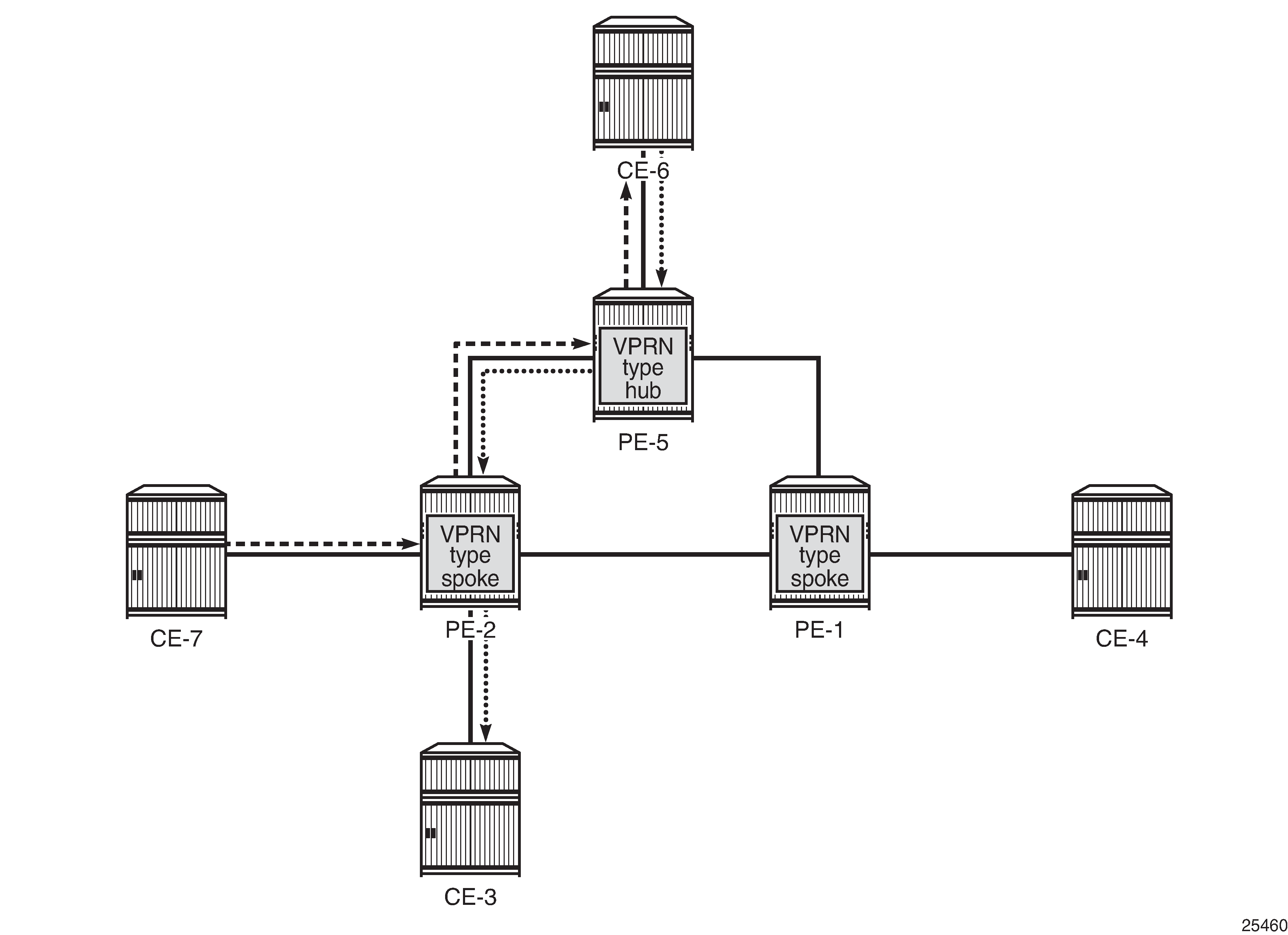
The only way for CE-7 to communicate with CE-3 is via hub site CE-6. The same applies to the communication between CE-7 and CE-4. The VPRN on PE-2 is configured as vprn-type spoke and has IP interfaces using SAPs or spoke SDPs that are considered spoke sites only. No direct communication between any of the spoke CE sites in the network is allowed.
Direct communication between the spoke CE sites is blocked using two techniques, as illustrated in CE hub and spoke control plane isolation.
-
Using the vprn-type spoke command under the vprn context as explained later.
-
The extended community configuration using route-target policies (this is not covered in detail in this chapter).
Figure 2. CE hub and spoke control plane isolation 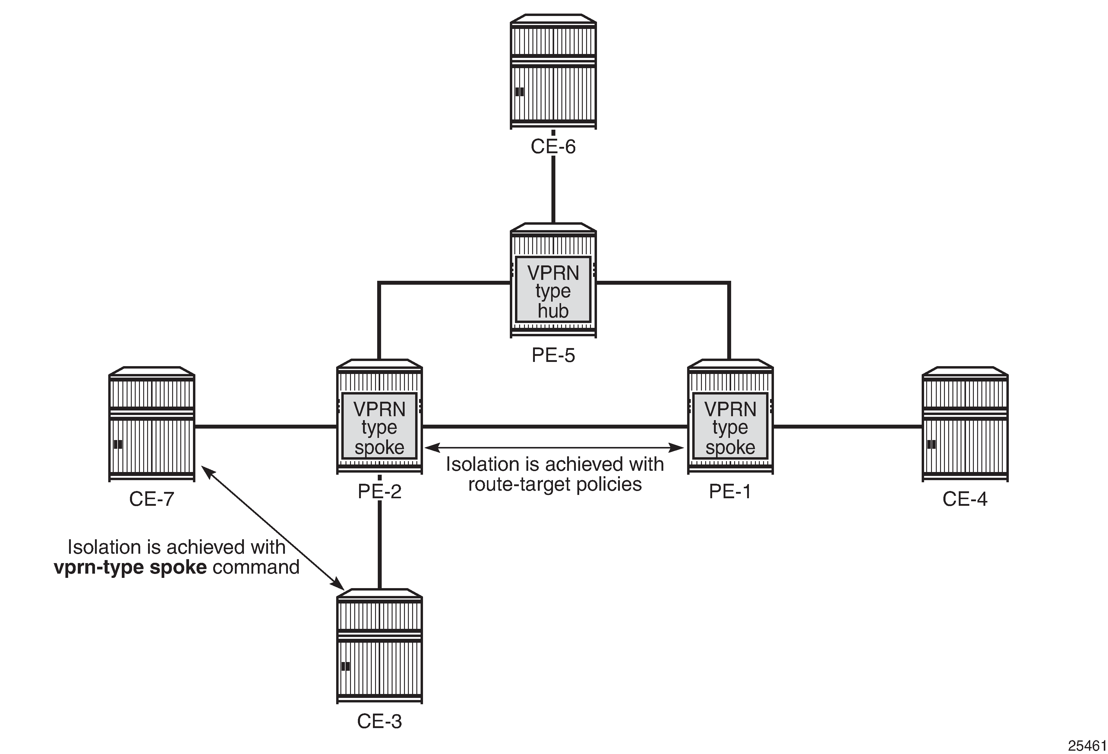
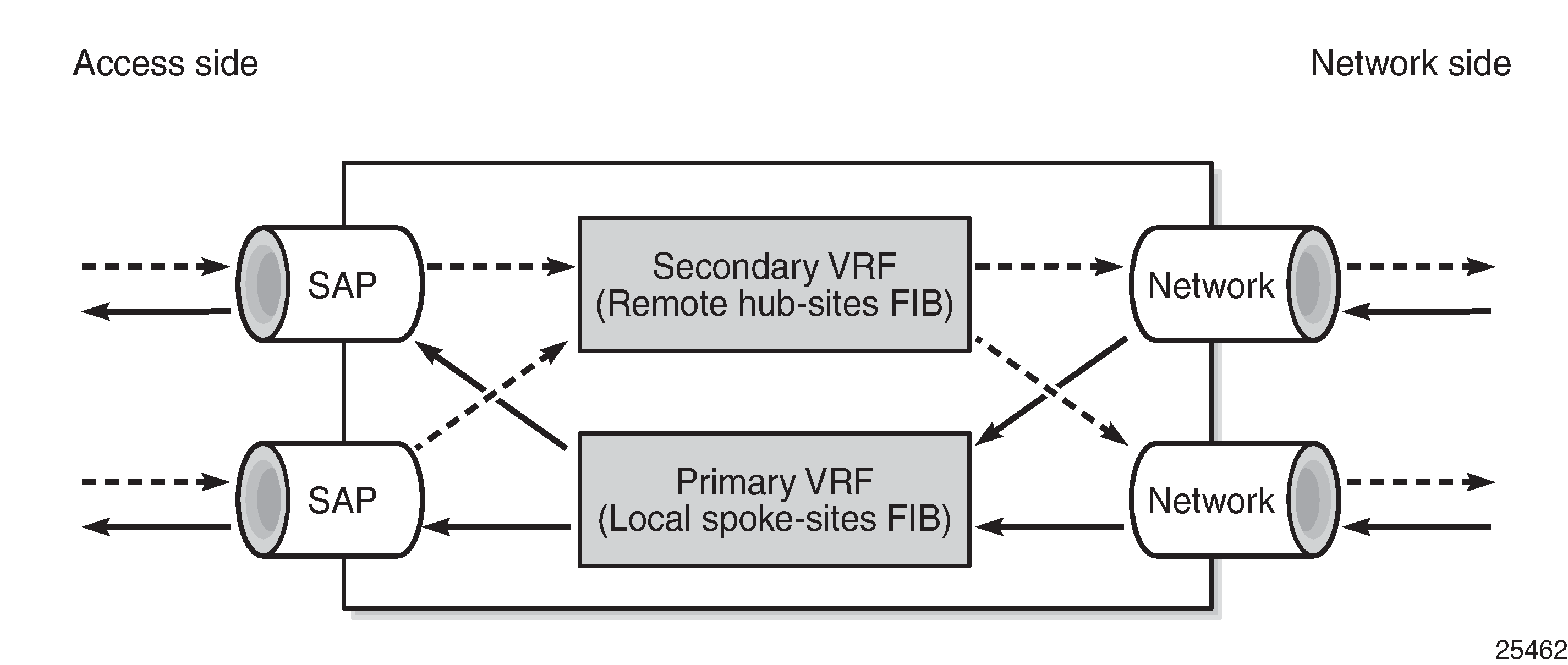
When a VPRN on a PE router is configured as vprn-type spoke, then the internal forwarding logic changes as demonstrated in Internal VPRN logic on a PE router.
-
VPRNs of type spoke create a primary and a secondary VRF internally to the VPRN:
-
The primary VRF is used for forwarding traffic from the network interfaces toward the IP interfaces using SAPs or spoke SDPs. This VRF is populated with routes learned from the spoke CE sites connected to the local PE through IP interfaces using SAPs or spoke SDPs.
-
The secondary VRF is used for forwarding traffic from the IP interfaces using SAPs or spoke SDPs toward the network interfaces or other VPRN instances. This VRF is populated with routes learned via MP-BGP from hub sites.
-
-
VPRNs of type spoke export routes using a specific extended community (for instance, spoke-ext-comm) via an export policy to identify them as spoke site originated routes.
-
This community is not hard-coded and has to be configured manually (see configuration example later).
-
-
VPRNs of type spoke import routes (using an import policy) received from other PEs or VPRN instances with a hub specific community only (for example, hub-ext-comm). Routes with spoke-ext-comm community are ignored.
-
This community is not hard-coded and has to be configured manually (see configuration example later).
-
-
Multiple VPRNs of type spoke and hub can coexist on the same PE if they use different VPRN instances.
-
The configuration of type hub and type spoke is mutually exclusive within one VPRN instance.
Configuration
The physical topology and addressing scheme are presented in CE hub and spoke topology and addressing scheme.
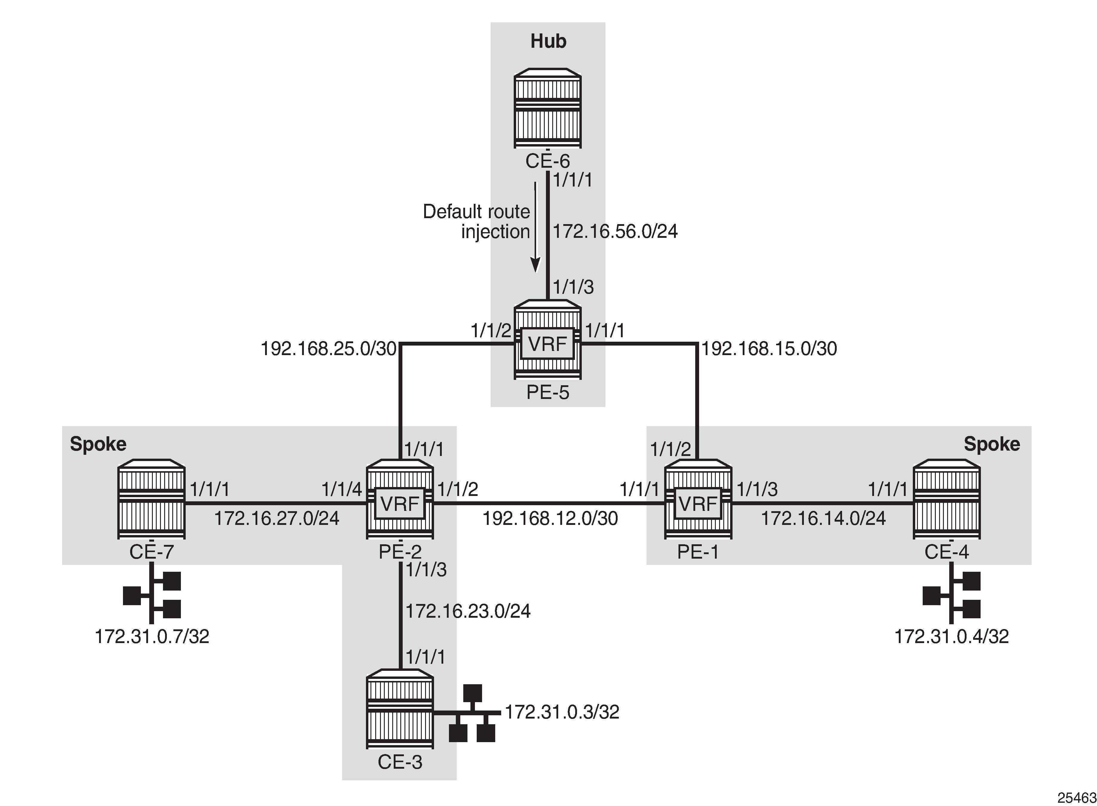
The configuration of PE-2 and PE-5 are the main focus of this example. The configuration of PE-1 is similar to that of PE-2.
Hub site configuration
Only the essential part of the configuration is provided for the hub site.
Vrf-import and vrf-export policies are used to manipulate the vrf-target in order to achieve logical isolation between the spoke sites in the network.
# on PE-5:
configure {
    policy-options {
        community "hub-ext-comm" {
            member "target:64500:11" { }
        }
        community "spoke-ext-comm" {
            member "target:64500:12" { }
        }
        policy-statement "export-ospf" {
            entry 10 {
                from {
                    protocol {
                        name [direct]
                    }
                }
                action {
                    action-type accept
                }
            }
            default-action {
                action-type accept
            }
        }
        policy-statement "vrf-export" {
            default-action {
                action-type accept
                community {
                    add ["hub-ext-comm"]
                }
            }
        }
        policy-statement "vrf-import" {
            entry 10 {
                from {
                    community {
                        name "spoke-ext-comm"
                    }
                }
                action {
                    action-type accept
                }
            }
            default-action {
                action-type reject
            }
        }
PE-5 is configured with VPRN "VPRN1" providing OSPF connectivity to customer CE-6.
# on PE-5:
configure {
    service {
        vprn "VPRN1" {
            admin-state enable
            description "VPRN type hub"
            service-id 1
            customer "1"
            vprn-type hub
            bgp-ipvpn {
                mpls {
                    admin-state enable
                    route-distinguisher "64500:15"
                    vrf-import {
                        policy ["vrf-import"]
                    }
                    vrf-export {
                        policy ["vrf-export"]
                    }
                    auto-bind-tunnel {
                        resolution any
                    }
                }
            }
            interface "int-PE-5-CE-6" {
                ipv4 {
                    primary {
                        address 172.16.56.1
                        prefix-length 24
                    }
                }
                sap 1/1/3:1 {
                }
            }
            ospf 0 {
                admin-state enable
                export-policy ["export-ospf"]
                area 0.0.0.0 {
                    interface "int-PE-5-CE-6" {
                        interface-type point-to-point
                        mtu 1500
                    }
                }
            }
At the same time, CE-6 is configured to advertise a default route which is used by all remote spoke CE sites to forward traffic via CE-6.
# on CE-6:
configure {
    policy-options {
        policy-statement "export-ospf-default" {
            entry 10 {
                from {
                    protocol {
                        name [static]
                    }
                }
                action {
                    action-type accept
                }
            }
        }
    }
    service {
        vprn "VPRN1" {
            admin-state enable
            service-id 1
            customer "1"
            interface "int-CE-6-PE-5" {
                ipv4 {
                    primary {
                        address 172.16.56.2
                        prefix-length 24
                    }
                }
                sap 1/1/1:1 {
                }
            }
            static-routes {
                route 0.0.0.0/0 route-type unicast {
                    blackhole {
                        admin-state enable
                    }
                }
            }
            ospf 0 {
                admin-state enable
                router-id 192.0.2.6
                export-policy ["export-ospf-default"]
                ignore-dn-bit true
                suppress-dn-bit true
                area 0.0.0.0 {
                    interface "int-CE-6-PE-5" {
                        interface-type point-to-point
                        mtu 1500
                    }
                }
            }
        }
Spoke site configuration
According to the example topology, two spoke VPRNs are present: one VPRN with two CE spoke sites connected is located on PE-2, and another VPRN with one spoke CE site on PE-1. The service configuration for PE-2 is as follows with the one for PE-1 being similar.
Vrf-import and vrf-export policies are used to build a hub-and-spoke topology in order to achieve a logical isolation between spoke sites connected to different PE routers.
# on PE-2:
configure {
    policy-options {
        community "hub-ext-comm" {
            member "target:64500:11" { }
        }
        community "spoke-ext-comm" {
            member "target:64500:12" { }
        }
        policy-statement "export-ospf" {
            default-action {
                action-type accept
            }
        }
        policy-statement "vrf-export" {
            default-action {
                action-type accept
                community {
                    add ["spoke-ext-comm"]
                }
            }
        }
        policy-statement "vrf-import" {
            entry 10 {
                from {
                    community {
                        name "hub-ext-comm"
                    }
                }
                action {
                    action-type accept
                }
            }
            default-action {
                action-type reject
            }
        }
PE-2 is configured with VPRN 1, which has OSPF connectivity to the customer CE-3 and CE-7. The vprn-type spoke command is used to prevent direct CE spoke to CE spoke communications for this VPRN.
# on PE-2:
configure {
    service {
        vprn "VPRN1" {
            admin-state enable
            description "VPRN type spoke"
            service-id 1
            customer "1"
            vprn-type spoke
            bgp-ipvpn {
                mpls {
                    admin-state enable
                    route-distinguisher "64500:12"
                    vrf-import {
                        policy ["vrf-import"]
                    }
                    vrf-export {
                        policy ["vrf-export"]
                    }
                    auto-bind-tunnel {
                        resolution any
                    }
                }
            }
            interface "int-PE-2-CE-3" {
                ipv4 {
                    primary {
                        address 172.16.23.1
                        prefix-length 24
                    }
                }
                sap 1/1/3:1 {
                }
            }
            interface "int-PE-2-CE-7" {
                ipv4 {
                    primary {
                        address 172.16.27.1
                        prefix-length 24
                    }
                }
                sap 1/1/4:1 {
                }
            }
            ospf 0 {
                admin-state enable
                export-policy ["export-ospf"]
                area 0.0.0.0 {
                    interface "int-PE-2-CE-3" {
                        interface-type point-to-point
                        mtu 1500
                    }
                    interface "int-PE-2-CE-7" {
                        interface-type point-to-point
                        mtu 1500
                    }
                }
            }
        }
For connectivity verification purposes, CE-3, CE-4, and CE-7 are configured to advertise their internal loopback interfaces via OSPF:
-
CE-3 advertises 172.31.0.3/32
-
CE-4 advertises 172.31.0.4/32
-
CE-7 advertises 172.31.0.7/32
# on CE-3:
configure {
    service {
        vprn "VPRN1" {
            admin-state enable
            service-id 1
            customer "1"
            interface "int-CE-3-PE-2" {
                ipv4 {
                    primary {
                        address 172.16.23.2
                        prefix-length 24
                    }
                }
                sap 1/1/1:1 {
                }
            }
            interface "lo0" {
                loopback true
                ipv4 {
                    primary {
                        address 172.31.0.3
                        prefix-length 32
                    }
                }
            }
            ospf 0 {
                admin-state enable
                router-id 192.0.2.3
                ignore-dn-bit true
                suppress-dn-bit true
                area 0.0.0.0 {
                    interface "int-CE-3-PE-2" {
                        interface-type point-to-point
                        mtu 1500
                    }
                    interface "lo0" {
                    }
                }
            }
        }
Hub site verification
The Routing Information Base (RIB) for VPRN 1 on hub site PE-5 lists all reachable networks:
[/]
A:admin@PE-5# show router 1 route-table

===============================================================================
Route Table (Service: 1)
===============================================================================
Dest Prefix[Flags]                            Type    Proto     Age        Pref
      Next Hop[Interface Name]                                    Metric
-------------------------------------------------------------------------------
0.0.0.0/0                                     Remote  OSPF      00h02m32s  150
       172.16.56.2                                                  1
172.16.14.0/24                                Remote  BGP VPN   00h01m07s  170
       192.0.2.1 (tunneled)                                         10
172.16.14.1/32                                Remote  BGP VPN   00h01m07s  170
       192.0.2.1 (tunneled)                                         10
172.16.23.0/24                                Remote  BGP VPN   00h01m01s  170
       192.0.2.2 (tunneled)                                         10
172.16.23.1/32                                Remote  BGP VPN   00h01m01s  170
       192.0.2.2 (tunneled)                                         10
172.16.27.0/24                                Remote  BGP VPN   00h01m01s  170
       192.0.2.2 (tunneled)                                         10
172.16.27.1/32                                Remote  BGP VPN   00h01m01s  170
       192.0.2.2 (tunneled)                                         10
172.16.56.0/24                                Local   Local     00h03m57s  0
       int-PE-5-CE-6                                                0
172.31.0.3/32                                 Remote  BGP VPN   00h01m01s  170
       192.0.2.2 (tunneled)                                         10
172.31.0.4/32                                 Remote  BGP VPN   00h00m40s  170
       192.0.2.1 (tunneled)                                         10
172.31.0.7/32                                 Remote  BGP VPN   00h00m30s  170
       192.0.2.2 (tunneled)                                         10
-------------------------------------------------------------------------------
No. of Routes: 11
Flags: n = Number of times nexthop is repeated
       B = BGP backup route available
       L = LFA nexthop available
       S = Sticky ECMP requested
===============================================================================
The forwarding table (FIB) for the primary VRF of VPRN 1 is displayed using following command. All remote spoke and hub sites are reachable via this VRF.
[/]
A:admin@PE-5# show router 1 fib 1

===============================================================================
FIB Display
===============================================================================
Prefix [Flags]                                              Protocol
  NextHop
-------------------------------------------------------------------------------
0.0.0.0/0                                                   OSPF
  172.16.56.2 (int-PE-5-CE-6)
172.16.14.0/24                                              BGP_VPN
  192.0.2.1 (VPRN Label:524284 Transport:LDP)
172.16.14.1/32                                              BGP_VPN
  192.0.2.1 (VPRN Label:524284 Transport:LDP)
172.16.23.0/24                                              BGP_VPN
  192.0.2.2 (VPRN Label:524284 Transport:LDP)
172.16.23.1/32                                              BGP_VPN
  192.0.2.2 (VPRN Label:524284 Transport:LDP)
172.16.27.0/24                                              BGP_VPN
  192.0.2.2 (VPRN Label:524284 Transport:LDP)
172.16.27.1/32                                              BGP_VPN
  192.0.2.2 (VPRN Label:524284 Transport:LDP)
172.16.56.0/24                                              LOCAL
  172.16.56.0 (int-PE-5-CE-6)
172.31.0.3/32                                               BGP_VPN
  192.0.2.2 (VPRN Label:524284 Transport:LDP)
172.31.0.4/32                                               BGP_VPN
  192.0.2.1 (VPRN Label:524284 Transport:LDP)
172.31.0.7/32                                               BGP_VPN
  192.0.2.2 (VPRN Label:524284 Transport:LDP)
-------------------------------------------------------------------------------
Total Entries : 11
-------------------------------------------------------------------------------
===============================================================================
The forwarding table for the secondary VRF of VPRN 1 is displayed using following command, including the secondary keyword. All local hub CE sites are reachable via this VRF.
[/]
A:admin@PE-5# show router 1 fib 1 secondary

===============================================================================
FIB Display
===============================================================================
Prefix [Flags]                                              Protocol
  NextHop
-------------------------------------------------------------------------------
0.0.0.0/0                                                   OSPF
  172.16.56.2 (int-PE-5-CE-6)
172.16.56.0/24                                              LOCAL
  172.16.56.0 (int-PE-5-CE-6)
-------------------------------------------------------------------------------
Total Entries : 2
-------------------------------------------------------------------------------
===============================================================================
Spoke site verification
The RIB for VPRN 1 on PE-2 (spoke VPRN) lists all reachable networks.
The other spoke sites connected to the remote PEs are not present in the routing table, in this example, CE-4 with prefixes such as 172.31.0.4/32 and 172.16.14.0/24.
The local interface addresses of PE-2 (172.16.23.1/32 and 172.16.27.1/32) are present in the routing table of VPRN 1, as follows. From a FIB point of view, these are reachable from any spoke VPRN, but the spoke CE’s router host addresses are not. This fact does not influence the data plane isolation for the customer networks.
[/]
A:admin@PE-2# show router 1 route-table

===============================================================================
Route Table (Service: 1)
===============================================================================
Dest Prefix[Flags]                            Type    Proto     Age        Pref
      Next Hop[Interface Name]                                    Metric
-------------------------------------------------------------------------------
0.0.0.0/0                                     Remote  BGP VPN   00h22m49s  170
       192.0.2.5 (tunneled)                                         10
172.16.23.0/24                                Local   Local     00h22m53s  0
       int-PE-2-CE-3                                                0
172.16.23.1/32                                Local   Host      00h22m53s  0
       int-PE-2-CE-3                                                0
172.16.27.0/24                                Local   Local     00h22m53s  0
       int-PE-2-CE-7                                                0
172.16.27.1/32                                Local   Host      00h22m53s  0
       int-PE-2-CE-7                                                0
172.16.56.0/24                                Remote  BGP VPN   00h22m49s  170
       192.0.2.5 (tunneled)                                         10
172.16.56.1/32                                Remote  BGP VPN   00h22m49s  170
       192.0.2.5 (tunneled)                                         10
172.31.0.3/32                                 Remote  OSPF      00h22m40s  10
       172.16.23.2                                                  10
172.31.0.7/32                                 Remote  OSPF      00h22m24s  10
       172.16.27.2                                                  10
-------------------------------------------------------------------------------
No. of Routes: 9
Flags: n = Number of times nexthop is repeated
       B = BGP backup route available
       L = LFA nexthop available
       S = Sticky ECMP requested
===============================================================================
The FIB for the primary VRF of VPRN 1 shows all local spoke sites are reachable via this VRF, as follows:
[/]
A:admin@PE-2# show router 1 fib 1

===============================================================================
FIB Display
===============================================================================
Prefix [Flags]                                              Protocol
  NextHop
-------------------------------------------------------------------------------
172.16.23.0/24                                              LOCAL
  172.16.23.0 (int-PE-2-CE-3)
172.16.23.1/32                                              HOST
  Blackhole
172.16.27.0/24                                              LOCAL
  172.16.27.0 (int-PE-2-CE-7)
172.16.27.1/32                                              HOST
  Blackhole
172.31.0.3/32                                               OSPF
  172.16.23.2 (int-PE-2-CE-3)
172.31.0.7/32                                               OSPF
  172.16.27.2 (int-PE-2-CE-7)
-------------------------------------------------------------------------------
Total Entries : 6
-------------------------------------------------------------------------------
===============================================================================
The FIB for the secondary VRF of VPRN 1 shows the remote hub site (address 172.16.56.0/24) is reachable via this VRF, as follows:
[/]
A:admin@PE-2# show router 1 fib 1 secondary

===============================================================================
FIB Display
===============================================================================
Prefix [Flags]                                              Protocol
  NextHop
-------------------------------------------------------------------------------
0.0.0.0/0                                                   BGP_VPN
  192.0.2.5 (VPRN Label:524284 Transport:LDP)
172.16.23.1/32                                              HOST
  Blackhole
172.16.27.1/32                                              HOST
  Blackhole
172.16.56.0/24                                              BGP_VPN
  192.0.2.5 (VPRN Label:524284 Transport:LDP)
172.16.56.1/32                                              BGP_VPN
  192.0.2.5 (VPRN Label:524284 Transport:LDP)
-------------------------------------------------------------------------------
Total Entries : 5
-------------------------------------------------------------------------------
===============================================================================
Spoke sites connectivity verification
Without the VPRN spoke type configuration in VPRN 1 on PE-2, CE-3 takes the shortest path to CE-7, which violates the hub-and-spoke design approach explained earlier.
# on PE-2:
configure exclusive
    service {
        vprn "VPRN1" {
            delete vprn-type
            commit
In this setup, a VPRN is configured on CE-3, but that is not necessary.
Traffic from CE-3 takes the shortest path to CE-7, because VPRN 1 on PE-2 is not configured with spoke type anymore.
[/]
A:admin@CE-3# traceroute 172.31.0.7 router-instance "VPRN1" numeric
traceroute to 172.31.0.7, 30 hops max, 40 byte packets
  1  172.16.23.1    2.54 ms  2.80 ms  2.93 ms
  2  172.31.0.7    3.28 ms  3.23 ms  3.05 ms
After enabling the vprn-type spoke feature on PE-2, CE-3 takes the longest path via hub CE-6 to reach CE-7, as it should.
# on PE-2:
configure exclusive
    service {
        vprn "VPRN1" {
            vprn-type spoke
            commit
[/]
A:admin@CE-3# traceroute 172.31.0.7 router-instance "VPRN1" numeric
traceroute to 172.31.0.7, 30 hops max, 40 byte packets
  1  172.16.23.1    2.34 ms  2.71 ms  2.58 ms
  2  0.0.0.0  * * *
  3  172.16.56.2    4.64 ms  4.62 ms  3.95 ms
  4  172.16.56.1    4.24 ms  4.44 ms  4.76 ms
  5  172.16.27.1    4.31 ms  4.30 ms  4.20 ms
  6  172.31.0.7    6.32 ms  6.39 ms  6.36 ms
Similarly, the long path is taken by CE-3 to reach CE-4, as follows. This is unrelated to the VPRN type. It is achieved by policies.
[/]
A:admin@CE-3# traceroute 172.31.0.4 router-instance "VPRN1" numeric
traceroute to 172.31.0.4, 30 hops max, 40 byte packets
  1  172.16.23.1    2.39 ms  2.80 ms  2.58 ms
  2  0.0.0.0  * * *
  3  172.16.56.2    4.69 ms  4.46 ms  4.23 ms
  4  172.16.56.1    4.53 ms  4.61 ms  4.12 ms
  5  172.16.14.1    5.83 ms  6.02 ms  6.24 ms
  6  172.31.0.4    7.00 ms  6.54 ms  6.99 ms
Conclusion
The VPRN type spoke feature completes the CE hub and spoke solution. It brings an additional level of simplicity, scalability, and flexibility to operators using this VPRN architecture for their customers.